Báo cáo hóa học: " New Applications of Electrochemically Produced Porous Semiconductors and Nanowire Arrays" pdf
Bạn đang xem bản rút gọn của tài liệu. Xem và tải ngay bản đầy đủ của tài liệu tại đây (616.29 KB, 5 trang )
NANO EXPRESS
New Applications of Electrochemically Produced Porous
Semiconductors and Nanowire Arrays
Malte Leisner
•
Ala Cojocaru
•
Emmanuel Ossei-Wusu
•
Ju
¨
rgen Carstensen
•
Helmut Fo
¨
ll
Received: 15 April 2010 / Accepted: 7 June 2010 / Published online: 15 June 2010
Ó The Author(s) 2010. This article is published with open access at Springerlink.com
Abstract The growing demand for electro mobility
together with advancing concepts for renewable energy as
primary power sources requires sophisticated methods of
energy storage. In this work, we present a Li ion battery
based on Si nanowires, which can be produced reliable and
cheaply and which shows superior properties, such as a
largely increased capacity and cycle stability. Sophisticated
methods based on electrochemical pore etching allow to
produce optimized regular arrays of nanowires, which can
be stabilized by intrinsic cross-links, which serve to avoid
unwanted stiction effects and allow easy processing.
Keywords Li ion batteries Á Porous Si Á Nanowires
Introduction
The availability of cheap and reliable secondary batteries
for energy storage is required in many fields of present and
particular future technology. Demands include storage
systems for renewable energy sources, batteries for por-
table devices like notebooks cell phones and the like, to
affordable and powerful electric cars. In state-of-the-art
battery concepts, a graphite anode is used together with a
cathode based on Li-compounds like, e.g., LiCoO
2
.To
enhance the capacity of the battery, Si is a promising
material for the use as anode. Si can incorporate very large
amounts of Li, leading to a nominal capacity of about
4,200 mAh/g, about a factor 11 larger than the current
state-of-the-art graphite anode [1]. The redox potential of
this system is also suitable for the use as anode, i.e. only a
small potential is needed to extract the Li from the Si.
During the incorporation of Li, phases like Li
12
Si
7
,Li
7
Si
3
,
Li
13
Si
4
, and Li
22
Si
5
are formed, and the corresponding
phase transitions invariably lead to an expansion of the
bulk Si of up to a factor of 4. In bulk Si, the resulting stress
is so large that it fractures, preventing the use in a battery.
A solution to this problem has been demonstrated by Chan
et al. [2]. In this work, Si nanowires have been used as Li
host material. The wires still have the superior Li incor-
poration properties of bulk Si, but also allow for the large
volume expansion without fracture, since a free increase in
their diameter is now possible. The nanowires in the work
of Chan et al. have been grown by a vapor-liquid-solid
(VLS) method, using Au droplets on a stainless steel sub-
strate. It was possible to generate nanowires with a diam-
eter around 90 nm, which were able to withstand 10
charging/discharging cycles.
Despite the success of this and follow-up [3] work, the
production method of the nanowires has some drawbacks.
Without substantial added process complexity, it is only
possible to grow rather unordered arrays of nanowires in a
small range of diameters. The optimal geometry of a
nanowire array, and thus maximum capacity, might there-
fore not be achievable. The applicability of the VLS
method to large-scale production has not yet been dem-
onstrated and is doubtful. In this work, we therefore
demonstrate a cheap and reliable method for the production
of optimized nanowire arrays by easy available and fairly
routine techniques.
M. Leisner (&) Á A. Cojocaru Á E. Ossei-Wusu Á
J. Carstensen Á H. Fo
¨
ll
Institute for Materials Science, Christian-Albrechts-University
of Kiel, Kaiserstrasse 2, 24143 Kiel, Germany
e-mail:
URL: />123
Nanoscale Res Lett (2010) 5:1502–1506
DOI 10.1007/s11671-010-9669-z
Production of Nanowire Arrays
The production of nanowire array anodes has been facili-
tated in a three-step procedure. (1) Electrochemical etching
of ordered macropore arrays into single-crystalline Si. (2)
Chemical over-etching of the macropores until the pore
diameters touch and only small wires remain between the
pores. (3) Deposition of a Cu diffusion barrier and contact
layer.
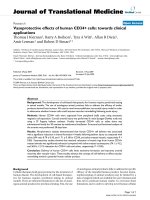
Figure 1 shows schematically the first two production
steps. Figure 1a shows a top view of the electrochemically
etched regular macropore array. The solid circles represent
the pores, and the dashed circles indicate the effect of the
subsequent chemical over-etch, which leads to the nano-
wires (top view) shown in Fig. 1b.
The third step is necessary to produce a working device.
Since the production method yields nanowires that are
directly attached to bulk Si, Li would be incorporated
during the charging/discharging cycle not only into the
nanowires, but also into the bulk Si, if no precautionary
measures are taken. Hence, a Cu layer, acting as diffusion
barrier, is galvanically deposited at the bottom of the
nanowire, i.e. at the nanowire-bulk Si interface. Figure 1c
shows this layer schematically.
Electrochemical Macropore Etching
The etching of macropores into n-type and p-type Si is by
now an established technique that allows to produce highly
ordered arrays of macropores with diameters in the range
between 200 nm and 10 lm, and as deep as 500 lm. For
detailed reviews of the technique, refer to [4–6].
In this work, macropores have been etched into (100)-
oriented p-type Si single-crystalline wafers with specific
resistivities in the range of (15–24) Xcm. As electrolyte, 5
wt% HF diluted in DMF has been used. All experiments
have been carried out at T = 20°C, the current density was
j = (3–23) mA/cm
2
, following an optimized profile over
time. The total etching time was in the range of 2 h,
yielding pore depths of about 150 lm.
Chemical Over-Etching Yielding Nanowires
Increasing the pore diameter by chemical over-etching has
been performed by using an acidic etchant consisting of a
mixture of HF/HNO
3
/HAc. Even though this generally
isotropic etchant is well studied for ‘‘flat’’ structures, cf.
e.g. [7], it is difficult to over-etch deep macropores
homogeneously, since the concentration of the necessary
species at the pore tips will always be different from the
one at the top. It is only possible to etch the pores homo-
geneously, if the reactions are not diffusion controlled,
necessitating very dilute acids. The drawback then is long
etching times, which may take up to 12 h in our case. This
might look like a severe obstacle for mass production on a
first view, but the problem might easily be overcome by a
batch process, i.e. many wafers are etched simultaneously
in one (cheap) etching station, cutting down the effective
production time.
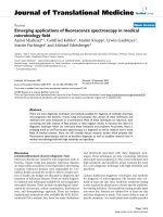
Figure 2 shows an example of the nanowire array pro-
duced. At the bottom, the former pore tips can still be seen.
The image also serves to demonstrate the flexibility of the
nanowires, which do not break, even for heavy bending as
shown.
Isolation by Galvanic Cu Deposition
The galvanic deposition of Cu onto Si is a standard process
in IC technology. Nevertheless, as in the case of the over-
etching of the pores, deposition of Cu on the bottom of a
dense forest of nanowires is not easily achieved, but can be
done, as has been demonstrated in [8–10]. As an electro-
lyte, a mixture of 300 ml H
2
O, 70 ml H
2
SO
4
, 5 g CuSO
4
,
0.1 g DTAC (1-dodecyl-trimethylammoniumchloride),
Cu
Si
(a) (b) (c)
Fig. 1 Schematic illustration of the nanowire array production steps.
a Top view of an electrochemically etched regular macropore array.
The dashed circles indicate the effect of the chemical over-etching,
which eventually yields the (black) nanowires shown in (b)(top
view). c The bulk Si has to be insulated from the Li by a Cu diffusion
barrier layer to avoid the incorporation of Li into the bulk Si. The Cu
layer also serves as electrical contact to the Si nanowires
Nanoscale Res Lett (2010) 5:1502–1506 1503
123
0.1 g SPS (Bis-3-sodiumsulfopropyldisulfide, and 0.1 g
PEG (Polyethylenglycol) has been used. Experiments have
been carried out at T = 20°C under a constant potential of
-0.5 V.
Cycling Test of the Anode
To test the potential anode, a half-cell has been build with a
Li reference electrode and a standard glass fiber separator.
As an electrolyte, 0.5 ml of LP-30 (Merck) has been used,
which essentially consists of dimethylcarbonate and ethy-
lencarbonate (1:1) with 1 mol/l of LiPF
6
as conducting salt.
All components have been mounted under Ar atmosphere
into a cylindrical Ti housing after previous removal of
residual water from the components. The half-cell has been
charged to C/10 (C: nominal capacity) for the first 10
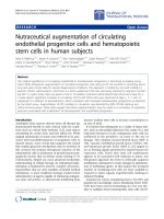
cycles, and to C/5 for the remaining cycles. Figure 3 shows
the measured efficiency in percent, which is defined as
charge to discharge percentage.
Initially the efficiency is low, which is due to condi-
tioning the Si (the initiation of the first phase transforma-
tion from Si to Si–Li) and also to the formation of the so-
called silicon–electrolyte interface (SEI). The irrevers-
ible losses are about 18.8%.
The cycle stability of the anode is very good and always
close to 100%. This indicates that the anode is mechani-
cally stable and no nanowires are detached during the
cycling. The cell has also been demounted after cycling
and inspected by SEM. The structural investigation into the
anode (not shown here) validates this statement; the anode
is mechanically still intact.
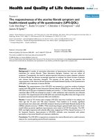
Test batteries have been assembled in a similar way, by
using a standard NCM (LiNi
x
Co
y
Mn
z
O
2
) cathode. The
battery was charged/discharged 65 times with a capacity C/
5, Fig. 4 shows the result.
The results are similar to the results obtained for the
half-cell set-up. The irreversible losses are small in com-
parison with other Si anodes, and a good cycle stability is
obtained.
Process Improvements
A big improvement of the production process can be
obtained if in a first step some small but sophisticated
changes to the macropore etching part are made that result
in a specific pore profile with depth. The pore profile in
Fig. 5 gives a schematic illustration of this optimization of
the pore form.
Most important are the constrictions, which can be
produced by lowering the etching current, which will result
in a decreased pore diameter. After the subsequent chem-
ical over-etching, nanowires will form everywhere except
Fig. 2 Ordered nanowire array produced in p-type Si
60
70
80
90
100
110
120
0102030405060
Cycles
Efficiency %
Fig. 3 Charge/discharge efficiency of the nanowire anode mounted
into a half-cell. The peak at cycle 44 is an artifact caused by a failure
in the temperature control
Cycling behavior
13.92%
0
1000
2000
3000
4000
5000
6000
010203040506070
Cycles
Specific charge [Ah/kg]
-5%
-3%
-1%
1%
3%
5%
7%
9%
11%
13%
15%
Irrev. charge loss
Charge Discharge Irrev. cap.
Fig. 4 Charge/discharge efficiency of a battery made of the nanowire
anode. Their reversible losses are small, a good cycle stability is
observed
1504 Nanoscale Res Lett (2010) 5:1502–1506
123
at the constriction places. There the pore walls are not yet
touching, which means that the nanowires are connected by
Si ‘‘bridges’’. These bridges provide a stabilizing layer
between the nanowires and prevent stiction, Fig. 6 illus-
trates this point.
Without stabilizing layer(s), the nanowires tend to show
stiction, i.e. they stick together at the tips like wet hair. The
surface is thus no longer well defined and cannot be easily
processed in follow-up processes. With the stabilizing
layers, this is different and the now well-defined surface of
the nanowires can be used to reduce the overall cost since
now the copper layer can be placed on top of the nano-
wires. Figure 7 shows the Cu layer on top of the nanowires.
In order to obtain a working anode, the nanowires need
then to be detached from the substrate. To allow easy
detachment of the nanowires, the end wedge shown in
Fig. 5 is included in the pore shape, producing very thin
nanowires at the point of contact to the Si substrate. The
nanowire layer now can be easily ‘‘zipped off’’ from the
Global wedge
shortens over-etch
time
End wedge
allows easy separation
from substrate
Constriction
prevents „stiction“
Fig. 5 An improved pore form produced by macropore etching
yielding several advantages to the battery production process. For
details, see the text
Fig. 6 Nanowire arrays. a Without stabilizing layer, the wires show stiction, i.e. stick together at the tips. b With three stabilizing layers, no
stiction occurs
Fig. 7 Cu layer deposited by sputtering on top of the stabilized
nanowire array
Fig. 8 The nanowire layer can be easily detached from the substrate
Nanoscale Res Lett (2010) 5:1502–1506 1505
123
substrate. Figure 8 shows this easy detachment of the
nanowire layer.
The last feature shown in Fig. 5 is the global wedge,
which makes the pore slightly bigger with increasing pore
depth. This is done to counter the aforementioned diffusion
limitation of the chemical over-etching speed at different
pore depths since now less material needs to be removed
deep down in the pores. Higher concentrations of the
etchant are now possible, significantly reducing the etching
time and thus production costs.
Conclusion
It has been demonstrated that optimized Si nanowire
anodes can be produced by cheap and reliable standard
techniques. The resulting structures are suitable for the use
as anodes in Li ion batteries of the future. First tests have
shown a substantially increased capacity and full cycle
stability.
Open Access This article is distributed under the terms of the
Creative Commons Attribution Noncommercial License which
permits any noncommercial use, distribution, and reproduction in any
medium, provided the original author(s) and source are credited.
References
1. B.A. Boukamp, G.C. Lesh, R.A. Huggins, J. Electrochem. Soc.
128, 725 (1981)
2. C.K. Chan, H. Peng, G. Liu, K. McIlwrath, X.F. Zhang, R.A.
Huggins, Y. Cui, Nat. Nanotechnol. 3, 1–31 (2008)
3. H. Fo
¨
ll, H. Hartz, E.K. Ossei-Wusu, J. Carstensen, O. Rie-
menschneider, Phys. Stat. Sol. RRL 4(1), 4 (2010)
4. V. Kochergin, H. Fo
¨
ll, Porous Semiconductors: Optical Prop-
erties and Applications (Springer, London, 2009)
5. H. Fo
¨
ll, M. Leisner, A. Cojocaru, J. Carstensen, Materials
accepted, (2010)
6. V. Lehmann, Electrochemistry of Silicon (Wiley-VCH, Wein-
heim, 2002)
7. X.G. Zhang, Electrochemistry of silicon and its oxide (Kluwer
Academic—Plenum Publishers, New York, 2001)
8. F.A. Harraz, K. Kamada, J. Sasano, S. Izuo, T. Sakka, Y.H.
Ogata, Phys. Stat. Sol. (a) 202(8), 1683 (2005)
9. C. Fang, E. Foca, S. Xu, J. Carstensen, H. Fo
¨
ll, J. Electrochem.
Soc. 154(1), D45–D49 (2007)
10. K. Fukami, Y. Tanaka, M.L. Chourou, T. Sakka, Y.H. Ogata,
Electrochim. Acta 54, 2197 (2009)
1506 Nanoscale Res Lett (2010) 5:1502–1506
123