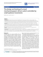
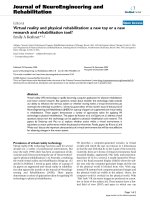
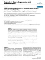
Báo cáo hóa học: "Research Article A Random Ant-Like Unicast Routing Protocol for Wireless Ad Hoc Sensor Networks and Performance Evaluation" pdf
Bạn đang xem bản rút gọn của tài liệu. Xem và tải ngay bản đầy đủ của tài liệu tại đây (702.34 KB, 7 trang )
Hindawi Publishing Corporation
EURASIP Journal on Wireless Communications and Networking
Volume 2010, Article ID 648235, 7 pages
doi:10.1155/2010/648235
Research Article
A Random Ant-Like Unicast Routing Protocol for Wireless Ad Hoc
Sensor Networks and Performance Evaluation
Yang Qin, Shenhao Liu, and Jinlong Wang
School of Computer Science and Technology, Harbin Institute of Technology Shenzhen Graduate School, Shenzhen 518055, China
Correspondence should be addressed to Yang Qin,
Received 12 February 2010; Accepted 12 June 2010
Academic Editor: Jiangchuan Liu
Copyright © 2010 Yang Qin et al. This is an open access article distributed under the Creative Commons Attribution License,
which permits unrestricted use, distribution, and reproduction in any medium, provided the original work is properly cited.
A random ant-like unicast routing (RAUR) protocol is proposed for wireless ad hoc sensor networks. In RAUR, when a source
node needs to find a routing path to a destination, it does not flood the network. Instead, the source selects one of its neighbors to
send out a route request packet. And the selected neighbor will also select one of its neighbors to forward the packet. The number of
nodes to for ward the searching message will be reduced. Hence, it could help to save the energy. In addition, the control overhead
will be less. In this paper, our approximated mathematical analysis shows that the successful rate in finding a path with only one
attempt is considerably high. Our research also shows that the RAUR will get higher successful rate through the larger number of
hops. We study the performance of the network using the proposed RAUR by simulation of Glomosim and compare it with the
routing protocols, DSR and AODV. The results show that RAUR could outperform in many metrics.
1. Introduction
A wireless sensor network consists of a large number of tiny
sensing devices, deployed in a region of interest. Each has
processing and wireless communication capabilities, which
enable it to gather information from the environment and
to generate and deliver report message to remote base nodes.
Since wireless sensor networks have an ad hoc topology and
there is no infrastructure in the networks, how to find a path
to send message to the destination is a challenging issue and
critical task in wireless sensor networks.
Existing major routing protocols for wireless sensor net-
works include LEACH [1], Directed Diffusion [2], Dynamic
Source Routing (DSR) [3], Ad hoc on Demand Distance
Vector (AO DV ) [4], Braided [5], MESH [6], Gossiping,and
SPIN. LEACH is built on the assumption that all sensor
nodes can reach the sink node directly, which means single
hop. Therefore, it is only applicable for networks with
small geographical size. Gossiping follows the principle of
randomness, it uses a randomly selected neighbor node
to forward the data packet. Gossiping does not flood the
network but extends the delivery time of data packet. SPIN
lets the source node flood ADV data packet and then send
the data packet to the request node. In SPIN,whenanode
wants to send message, if all neighbor nodes do not need the
data, it will lead to the data can not be transmitted to other
remote nodes.
Except LEACH, all the other protocols support multihop
routing. Depending on how many copies of one data
packet are forwarded to the destination simultaneously,
these multihop routing protocols can be divided into two
categories: single-path routing and multipath routing. In
single-path routing, for each data packet, there is only
one copy traveling along one path in the network. While
in multipath routing, multiple copies of one packet are
transmitted in parallel along different paths to the same
destination. Among the above-mentioned multihop proto-
cols, only MESH is explicitly claimed as multipath routing.
Braided builds multiple paths for a data delivery, but only one
of them is used, while others are maintained as backup paths.
Directed Diffusion can be single-path or multipath routing
depending on how many paths are reinforced by sink node.
DSR, AODV, Gossiping, and SPIN are single-path routing
protocols for ad hoc topology wireless sensor networks. Most
of the above protocols use broadcast to do routing, which will
cause high energy consumption and high control overhead.
Recently, one model that has received attention is based
on the communication paradigm of ants [7–10]. Ants com-
municate by means of pheromones deposited on the ground
as they move. When an ant discovers food, for example,
2 EURASIP Journal on Wireless Communications and Networking
it returns to the nest, laying down a pheromone trail that
other ants may follow to its source, the food. Pheromones
diffuse and evaporate; diffusion widens the trail, while
evaporation provides a time limit on its availability. Ants
interpret a wide trail, which is diffused and expanded by the
pheromones of many ants, as being more significant than
a narrow one, of course, no longer use an evaporated trail.
The ants thereby establish a complicated organized behavior
based solely on the relatively simple behavior of individuals
without central control.
This communication model is app ealing for wireless
sensor networks. Basically, the ant mode considers the ant
nest as information source (message origination) node, the
food as an information sink (destination) node, and ants as
messages (packets). The ground between nodes is considered
a collection of intermediate nodes. For destination node to
receive message in this model, it must first tr ansmit messages
advertising its presence. This advertisement message is
passed from node to node in a random, unicast way. When
the origination node sends a data message, it sends it to a
random neighbor, which checks its routing table to see if it
has a path to the destination. If not, it forwards the data
message to a random neighbor. If this random neighbor
has a path to the destination, it forwards the message to
the neighbor according to the path to the destination. The
message will be delivered to the destination node eventually
if it is given enough time to forward.
However, the studies of ant-like routing algorithm on
wireless sensor networks are not very sufficient, especially
the per formance evaluation and comparison with other
algorithm are not enough. In this paper, we present a random
ant-like unicast routing (RAUR) algorithm and provide
performance comparison with other routing algorithms. We
also conduct an approximated mathematical analysis for
the RAUR to analyze its performance. RAUR is a source
routing-based algorithm which is different from other ant-
like algorithms. In RAUR, the path discovery process will be
invoked only when the origination node does not have the
path to the destination, or the intermediate node finds that
the path from the source is fault. After the node finds the
path, the data message (packet) will be sent according to the
path found.
The rest of this paper is organized into the following
sections. Section 2 provides a brief description of the pro-
posed algorithm, RAUR. This is followed by the explanation
of the approximated analytical model for proposed scheme
in Section 3. Sections 4 and 5 present simulation model, per-
formance metrics and results from the simulations carried
out respectively. This is followed by a conclusion to the paper
and suggestions of areas where further work can be done in
the last section.
2. Random Ant-link Unicast
Routing (RAUR)
This section describes RAUR, the proposed algorithm. Our
scheme is a source routing-based protocol like DSR. It is
simple and can be easily implemented.
We first state the information kept at the nodes and
the types of control packets used in the algorithm are next
defined. T hese are then followed by a description of the
algorithm’s operation.
2.1. Information Kept at Nodes. Below are the information
kept at any node, X, running RAUR. A brief description is
given for each item
2.1.1. Routing Cache Table. The routing cache table holds the
routes, a node discovered during route discovery or from
overheard packets in the network. Each ent ry in the cache
table holds a destination address, hop count, source route
buffer, and entry’s insertion time. All entries in the table are
sorted by the destination address and hop count.
2.1.2. Data Packet Buffer. Data packets are buffered in node
X’ s data packet buffer when host X is performing route
requests for the destinations of the data packets in order for
these packets to be sent.
2.1.3. Neighbor List. The neighbor list of node X records the
addresses of nodes that node X has lear nt as its neighbors.
2.1.4. Route Request Table. The route request table records
the route request information when the source node has
initiated a route recovery to search for a destination node.
Each entry inserted into the table has a source address,
destination address, nature of request, next-hop selected list,
and request time.
2.1.5. Table of Processed Route Requests. The table of pro-
cessed route requests is a record of the route requests from
other nodes recently processed by node X. Several records
can be kept for each host initiating the requests. Each
record consists of the address of the queried destination and
an identification of the route request packet sent for that
request.
2.2. Operation of the Algorithm. There are three kinds of
control packets used in RAUR—route request packets
(RREQ), route reply packets (RREPs), and route error
packets (RERR).
To facilitate the routing of data packets in the network, it
is necessary for nodes to conduct route discovery operations
to look for routes that lead to desired destinations. This can
happen in one of the following cases:
(1) a source node needs to find a path for a data packet
for a desired destination,
(2) a node forwarding a data packet detects a fault
between itself and the next-hop node specified in the
packet header. The node will then need to find an
alternative path to the specified destination.
Whenanodeoperatesroutediscovery,itchecksits
neighbor list and randomly selects one neighbor to forward
EURASIP Journal on Wireless Communications and Networking 3
or send message (RREQ). The route discovery, is designed
to reduce the energy consumption and control overhead
information in the network.
The route request operations function in a same manner
in both the cases mentioned earlier. The operations will
be described in detail in the next subsec tion for the
second case, where they are used in the route discovery
mechanism for intermediate nodes meet invalid paths.
The described operations can also be applied to the first
case, where a source node needs to find a path to a
destination. The mechanisms that enable a more efficient
route recovery are described in the last subsection of this
section.
An example of flooding (broadcast) and point-to-point
(unicast) packets transmission is explained in the following.
The transmitting node sends packets to all nodes in flooding.
In the case of point-to-point, the transmitting node sends
packet to only one intended receiving node. As a result of this
practice, some RREQs may not find a path to the destination
if the given searching time is short. It is very interesting
to study the efficiency of RAUR. What is the searching
successful rate will be a critical metric to evaluate the routing
algorithm. We will conduct an approximated analytical
model simulation as a model to study the effectiveness of
RAUR in Section 3.
2.2.1. Route Discovery Mechanism. The route discovery
mechanism in RAUR typically involves conducting route
requests. This subsec tion describes the operations involved
in the route discovery mechanism.
RAUR differs from AODV and DSR in the way the RREQ
is being sent. It uses unicast to send RREQ, whereas AODV
and DSR use broadcast. In RAUR, a selection of the next
hop has to be made before sending the RREQ. The choice of
selecting a neighbor to receive RREQ in RAUR is crucial and
critical to ensure data delivery, reasonable latency, and low
bandwidth usage. Thus, RAUR routing protocol employs the
following technique and criteria for selection of its neighbor
during route discovery.
When selecting a neighbor, the neighbor must not be a
node in the upstream route path. This check is part of the
feature of source routing protocol to prevent looping in the
network.
Before a source node sends an RREQ packet to its neigh-
bor node to initiate route recovery, it updates the packet
with the source address, destination address, and its neighbor
addresses into the route buffer in RREQ. It then selects a
node from its neighbor table and forwards the RREQ to its
neighbor.
As we know that the intermediate node in RAUR will
generate RREQ for searching a path if it meets a “link”
failure when forwarding a packet. After this intermediate
node receives the RREP, it will send back to the source of
the data upstream nodes. This enables the upstream nodes to
update their routing tables with the new path corresponding
to the “link” failure. Since RAURs inform the upstream nodes
to update the routing table related to the failure link to
providecorrectroutepathinthefuture,weconsiderithaving
the function of “fault tolerance.”
Timeout of RREQ and Loop Free. When requesting for a new
route, an RREQ originator sends the RREQ only to one of
its neighbors that are randomly chosen. However, as a result
of this practice, RREQs are not guaranteed to end up at the
queried destination or at a node with a valid route to the
destination.
To increase the possibility of finding a path to the
destination, RREQs are given a timeout value so that another
RREQ can be sent to another neighbor when the old one
times out. When an originator does not receive any response
to an RREQ after it times out, it sends another RREQ for the
same destination to another randomly chosen neighbor. This
is repeated as long as the allowable number of continuous
route request attempts is not exceeded, and as long as
the originator still has neighbors to forward the RREQ.
Meanwhile, the old RREQ is considered expired. Nodes that
encounter the expired RREQ wil l not process it and any
RREPs received for it will be ignored.
Choosing a suitable timeout value for different kinds of
network configuration may be a challenge if this approach
isadopted.Onepossiblesolutiontothisistohavethe
hosts that keep track of the traffic condition and number
of neighbors they have. They can then use an algorithm
to dynamically compute a t imeout value suitable for that
particular situation. For example, such timeout could be
set according to the Maximum number of hops we allow
for each RREQ to be forwarded Let us denote, time-
out as T
out
and Maximum number of hops as Max
hop
,
assuming the average waiting time at each hop is W
ave
.
Then, we have T
out
= Max
hop
× W
ave
. We would increase
the Max
hop
by one if the previous RREQ failed and set
the W
ave
according to the average queuing delay from
simulation.
The node that generated the RREP with the invalid path
will realize the invalid path when it receives the data packet
and tries to forward it according to the path found in its
header. The data packet is treated like any data packet that
cannot be forwarded at a node due to an invalid path in its
header. The node carries out a route discover y operation,
as described earlier, to find an alternative path for the data
packet.
Since RAUR is a source routing algorithm, when the
intermediate node tries to forward the RREQ, it can check
the path in the RREQ’s header. In an RREQ, this records
the path history. By checking the path in the RREQ’s
header, RAUR can avoid forwarding the RREQ or packet
to the nodes it traversed before, and then it can avoid
loop.
2.2.2. Route Maintenance Mechanism. In some cases, for
example, when a destination host leaves a network, the
route recovery mechanism may not yield any alternative
path to this destination. In this case, the source node will
need to be informed of the invalid route. This information
is transmitted in the RERR packets. There are some more
efficient route ways to improve the efficiency for route
recovery. for example, making use of the omnidirectional
property of wireless transmissions. As this is not the focus
of this paper, we will not discuss the additional mechanism.
4 EURASIP Journal on Wireless Communications and Networking
3. Performance Analysis
The successful probability in finding a path to the queried
destination is an important factor in evaluating the efficiency
of the routing protocols. The traditional flooding routing
protocols have the advantages that they normally have high
success rate in finding the path to destination, however,
flooding protocols always try to use all the resources to
search, which cause bandwidth to be not enough for the data
packets, further more it will consume more energy in the
network as it involves more nodes to forward.
It is important for us to evaluate the efficiency of RAUR,
since RREQ in RAUR may not find a path to the destination
when the searching stops. We derive an approximated
mathematical analysis to evaluate the success rate of route
in RAUR. In the later section, we will also conduct the
simulation to compare it with the analytical model.
We will make a simple analysis for the unicast scheme
based on the average case, the neighbor is selected randomly.
Let us use a matrix M of size N
× N as the adjacent mat rix
of the network topology, where N is the number of hosts
in the network. M
sd
is 1 if there is a one-hop path from s
to d, otherwise it is 0. M
2
= M × M, where the entry M
2
sd
means the number of paths (of course, exclude the paths
with loops), whose path length is 2 from node s to node d.
Similarly, M
N−1
is the matrix saved all the number of paths
with path length of N
− 1.
Of course, we exclude the paths with loops. It can be
implemented by writing a program to check every node on
each path, if there is any one node repeated within one path,
it means a loop. Let us denote the maximum number of hops
as Max H.MaxH means the maximum number of hops each
path can constrain.
We consider the worst case scenario; the network nodes
have little information about other nodes. For example, no
nodes will have the information for the destination node
except the destination node itself. If it is given enough time
to process all the RREQs, the probability of an RAUR RREQ
to successfully find a path to the queried destination can be
calculated in the following:
R
t
=
Max H
i
=1
M
i
sd
D∈N,D
/
= s,d
M
Max H
sD
+
Max H
i=1
M
i
sd
,(1)
where
Max H
i=1
M
i
sD
is the total number of successful paths
with various paths length from source s to destination d.
And
D∈N,D
/
= s,d
M
Max H
sd
is the total number of failure paths
when an RREQ terminates its searching at any other nodes
except the queried destination node d while the RREQ has
exceeded the maximum number of hops, Max H, which can
be set from 1 to N
− 1.
Theabovecomputationisdoneunderworstcasesce-
nario that all the hosts have no route information about the
other nodes except its neighbors. A further realistic analysis
is proposed to model the query successful rate with every
node having routing table and has the possibility of caching
a valid route to the destination. We use the results of R
t
obtained from previous computation as inputs to obtain
a more realistic results for query paths in a network of nodes
with routing table.
Without losing generality, we take a specified destination
as node D. We take N as the total number of nodes in the
network, we define the nodes that have valid routes to node
DasLuckynodesasL,whereC is the number of nodes
that has been covered by the query path and where Max H
is the maximum hops the query path can take. Thus, the
probability of a query path does not pass any lucky nodes
as the follows:
R
in
(
L
)
=
Max H
C
=1
((
N
− C
)
− L
)
(
N
− C
)
,(2)
where N must be greater than C and ((N
− C) − L)must
be greater than 0. In this probability, if ((N
− C) − L)isless
than or equal to zero, it means that there are no more unlucky
nodes in the network. Therefore every other node is a lucky
node and the probability of getting an unlucky node is 0%.
Thus in any route path, any node before it is covered by the
query, is considered unlucky node. We define R
final
to be the
probability of the successful rate in finding a valid path to a
destination. The results of R
in
(L) are obtained from Min L to
Max L and are used to find R
final
R
final
=
Max L
L=Min L
(
R
in
(
L
)
× R
t
+
[
1 − R
in
(
L
)
]
× 100%
)
Max L − Min L
,
(3)
where 1
− R
in
(L) is the probability of reaching a lucky node,
where R
t
is the blind search rate given by (1). Max L is the
number of maximum lucky nodes for a specified destination.
Min L is the number of minimum lucky nodes for a specified
destination. However, the number for the lucky nodes in
the network is very hard to estimate. We have to make
some approximation. We consider the condition when a new
node, say Node J, joins the network. At the beginning, no
lucky nodes for it, as no other nodes have the valid route
information to it. During the pause time, more packets are
generated according to the uniform distributed destinations.
Some nodes generate packets destine the new node J. The
number of the packets which choose Node J as destination
can be expressed as follows.
Max L
=
λ × P
N
,(4)
where P is the pause time, N is the total nodes in the network,
and λ is the packet arrival rate in the whole network. This
is the number of packets which are destined to node J.
Assuming the different packets are uniformly generated from
different source nodes, then at least these nodes will have
some route path to Node J after this round searching. Hence,
this can be considered as lucky nodes for Node J next time.
The maximum lucky nodes will be the total number of nodes
in the network, (N
− 1).Hence,MaxL<N. The minimum
number of lucky nodes, Min L,foranynodewillbebigger
than zero. Since more nodes have routing information when
the network achieves a steady state or runs for long enough
time, the Min L will be increasing while the pausing time
increases. Obviously, in a dense network, the number of
lucky nodes will also be big.
EURASIP Journal on Wireless Communications and Networking 5
Success rate (n = 25, h = 6)
0
20
40
60
80
100
(%)
0 20 40 60 80 100 120
Pause time (secs)
Analysis results
Simulation results
Figure 1: Success rate of finding path (n = 25).
0
20
40
60
80
100
(%)
0 20406080100120
Pause time (secs)
Analysis results
Simulation results
Success rate (n
= 49, h = 6)
Figure 2: Success rate of finding path (n = 49).
4. Simulation Evaluation and Discussion
In this section, we will conduct a simulation experiment
to present the comparison of analytical results with the
simulation results and also present the comparison of the
performance of different routing protocols, including DSR,
and AODV with RAUR in simulation in the following
sections. Since RAUR is a single-path routing protocol, hence
we compare it with DSR and AODV which are also single-
path routing protocol to evaluate its performance.
The simulation was conducted using Glomosim Network
Simulator (v2.03) developed by UCLA. The simulation
environment for project is set similar to those of simulation
conducted by other papers [4]. The network is defined to
have 2 Mbps bandwidth. The nodes are randomly placed in
rectangular fields, 2200m
× 600 m for different simulation.
A rectangular field is chosen so that the t ransmission for
faraway nodes can also be evaluated. The mobility model
used is Modified Random Waypoint [11]witheachnode’s
mobility rate randomly set b etween 0 and 20 meters per sec.
As we think the node in sensor networks has relatively static
property, the pause time is as high as 300 sec. The radio range
for the node is 250 m. Every node in the network m aintains
two interface queues of w ith 64 packets size each. In the
simulation, there are 40 source nodes will continuously
generate packets at the packet rate to destinations. The packet
rate is varying from 1 to 100 packets per second. The data
packet size is fixed at 512 bytes.
49 nodes at arrival rate 20 pkt/s
70
75
80
85
90
95
(%)
56789
Hops
Pause time 40 s
Pause time 45 s
Pause time 50 s
Pausetime55s
Pausetime60s
Figure 3: Success rate of finding path versus hops (n = 49).
25nodesatarrivalrate20pkt/s
70
75
80
85
90
95
100
6 7 8 9 10 11 12 13 14 15
Hops
5
(%)
Pause time 10 s
Pause time 15 s
Pause time 20 s
Pausetime30s
Pause time 25 s
Figure 4: Success rate of finding path versus hops (n = 25).
The following are the performance metrics used in our
simulations.
4.1. Percentage of Data Packets Successfully Delivered. The
percentage of data packets successfully delivered is the
percentage of data packets that are eventually delivered to
their respective destinations over the total packets generated.
4.2. Average Packet Late ncy. The average packet latency is the
average amount of time a packet that is successfully delivered
to its destination spends in the network.
4.3. Energy Consumption. The energy usage is in arbitrary
energy units, or eu. We assumed that a node consumes
0.03 eu/second when idle, 0.3 eu/second while receiving, and
0.6 eu/second while transmitting. T hese values are consistent
with values measured on real-world wireless devices [12].
4.4. Throughput. It measures the average rate of data that are
delivered to the destination in bit per sec. The simulation
presents the average throughput for a node. Generally for
6 EURASIP Journal on Wireless Communications and Networking
0
0.1
0.2
0.3
0.4
0.5
0.6
0.7
0.8
0.9
1
Packet delivery fraction
0 102030405060708090100
Packet sending rate (pkt/s)
AODV
DSR
RAUR
Figure 5: Packet delivery rate.
0
0.5
1
1.5
2
2.5
3
3.5
4
4.5
0 102030405060708090100
Packet sending rate (pkt/s)
End-to-end delay (s)
AODV
DSR
RAUR
Figure 6: End-to-end delay.
any network, it is preferred to have a throughput as high as
possible.
It is very important to investigate the effectiveness of pro-
posed RAUR algorithm. Hence, we study the performance
of RAUR in the success rate of finding a path using the
proposed algorithm in this section. Figures 1 and 2 shows the
comparison of simulation and analytical results of the success
rate of finding a path in the 49-nodes network and 25-nodes
network with number of hops is 6, plotted against the pause
time. We can see that the approximated analysis is close to
the simulation results and while the pause time increases, the
success rate also increases. It is to be expected, since a larger
pause time decreases the level of mobility. It demonstrates
in both analytical and simulation results that RAUR could
reach quite high success rate if it is given a big enough
number of hops. Figures 3 and 4 show different success rate
of finding a path versus number of hops at different pause
time by analytical results. The results give out an insight of
performance changing trends of RAUR routing scheme.
0
10
20
30
40
50
60
70
80
0 102030405060708090100
Packet sending rate (pkt/s)
×10
3
AODV
DSR
RAUR
Average throughput (bps)
Figure 7: Average throughput.
Then, we will present some simulation results from
network of 2200 m
× 600 m, with 100 nodes in the following
performance metrics: packet delivery, average delay, and
throughput. The simulation results demonstrate the effec-
tiveness of the proposed scheme.
4.5. Comparison of Percentage of Data Packets Successfully
Delivery. Figure 5 shows the packet successfully delivery of
different protocols. It is observed that RAUR will outper-
form DSR and AODV. The operational feature of RAUR
contributing to its superior performance is: the route request
operations that involve sending an RREQ to only one
neighbor at a time.
By allowing only one RREQ to be forwarded at anytime
during a route request operation, the control overhead is
significantly reduced. With a lighter tr affic in the network,
both data and control packets experience lower delay.
4.6. Comparison of Average Packet Latency. RAUR showed
better performance when the number of sending source
increased to 40 in Figure 6. Of the three routing protocols,
RAUR was able to perform better. The lower packet latency
for RAUR is expected as a result of the route recovery
mechanism used in the algorithm. RAUR generates fewer
control overhead as it uses unicast scheme and could save
bandwidth for the data packet. Since DSR and AODV
generate more control overheads, it leads to a larger portion
of bandwidth to be taken up by control overhead, hence, the
data packets will experience longer delay.
4.7. Comparison of Throughput and Energy Consumption.
Figure 7 show the variation of throughput with pause time
in 2200 m
× 600 m wireless sensor network. Similarly, it is
observed the RAUR has much better performance. In Table 1
shows the energy usage for different protocols. As can be
seen, RAUR outperforms the other protocols.
EURASIP Journal on Wireless Communications and Networking 7
Table 1: Energy consumption comparison for RAUR, DSR, and
AODV.
RAUR DSR AODV
Energy (eu) 3709 7689 4978
5. Conclusion and Future Work
One of the objectives of this paper is to investigate the
motivation for deploying a unicast distributed routing
algorithm in wireless sensor ad hoc networks.
The random ant-like unicast routing (RAUR) scheme is
proposed and simulations were run to compare the network
performance of networks running on RAUR and those
running on DSR, AODV. RAU R outperforms in most of the
simulations. With higher traffic load, RAUR has shown more
tolerance to the increase of network traffic load, it is scalable
as the routing load change is small and gradual even at higher
number of sending sources. The advantages of RAUR are
due to its unicast routing mechanism. We have also provided
an approximated analytical model for RAUR to give out an
insight of its performance changing trends.
In future studies, more realistic traffic, for example, TCP
or UDP traffic application and multimedia traffic, will be
used for further investigation of the performance of RAUR.
Some other arbitrary network field with low node density
will be used to examine the RAUR.
References
[1] W. R. Heinzelman, A. Chandrakasan, and H. Balakrish-
nan, “Energy-efficient communication protocol for wireless
microsensor networks,” in Proceedings of the 33rd Annual
Hawaii International Conference on System Siences (HICSS
’00), p. 223, January 2000.
[2] C. Intanagonwiwat, R. Govindan, and D. Estrin, “Directed
diffusion: a scalable and robust communication paradigm
for sensor networks,” in Proceedings of the 6th Annual
International Conference on Mobile Computing and Networking
(MOBICOM ’00), pp. 56–67, Boston, Mass, USA, August 2000.
[3] D. B. Johnson, et al., “Dynamic source routing in ad hoc
wireless networks,” in Mobile Computing,T.Imielinskiand
H. F. Korth, Eds., chapter 5, Kluwer Academic Publishers,
Dodrecht, The Netherlands, 1996.
[4] C. E. Perkins and E. M. Royer, “Ad hoc on-demand distance
vector routing,” in Proceedings of the 2nd IEEE Workshop on
Mobile Computing Systems and Applications, pp. 99–100, 1999.
[5] D. Ganesan, et al., “Highly-resilient, energy-efficient mul-
tipath routing in wireless sensor networks,” ACM Mobile
Computing and Communications Review, vol. 5, no. 4, pp. 11–
25, 2001.
[6] F. Ye, S. Lu, and L. Zhang, “GRAdient Broadcast: a
robust, long-lived sensor network,” Tech. Rep., UCLA, 2001,
/>[7] R. Schoonderwoerd, J. L. Bruten, O. E. Holland, and L. J.
M. Rothkrantz, “Ant-based load balancing in telecommunica-
tions networks,” Adaptive Behavior, vol. 5, no. 2, pp. 169–207,
1996.
[8] G. Li, S. Zhang, and Z. Liu, “Distributed dynamic routing
using ant algorithm for telecommunication networks,” in
Proceedings of the IEEE Internat ional Conference on Commu-
nications (ICC ’00), vol. 2, 2000.
[9] T. Michalareas and L. Sacks, “Link-state & ant-like algorithm
behaviour for single-constrained routing,” in Proceedings of the
IEEE Workshop on High Performance Switching and Routing,
pp. 302–305, May 2001.
[10] E. H. Callaway, Wireless Sensor Networks: Architectures and
Protocols, Auerbach Publications, CRC Press, Boca Raton, Fla,
USA, 2004.
[11] J. Yoon, M. Liu, and B. Noble, “Random waypoint considered
harmful,” in Proceedings of the 22nd Annual Joint Confer-
ence of the IEEE Computer and Communications Societies
(INFOCOM ’03), pp. 1312–1321, April 2003.
[12] C. E. Jones, K. M. Sivalingam, P. Agrawal, and J. C. Chen,
“A sur ve y of ene rg y e fficient network protocols for wireless
networks,” Wireless Networks, vol. 7, no. 4, pp. 343–358, 2001.