báo cáo hóa học:" Scan speed control for tapping mode SPM" docx
Bạn đang xem bản rút gọn của tài liệu. Xem và tải ngay bản đầy đủ của tài liệu tại đây (374.48 KB, 10 trang )
This Provisional PDF corresponds to the article as it appeared upon acceptance. Fully formatted
PDF and full text (HTML) versions will be made available soon.
Scan speed control for tapping mode SPM
Nanoscale Research Letters 2012, 7:121 doi:10.1186/1556-276X-7-121
Aleksey V Meshtcheryakov ()
Vjacheslav V Meshtcheryakov ()
ISSN 1556-276X
Article type Nano Express
Submission date 30 September 2011
Acceptance date 14 February 2012
Publication date 14 February 2012
Article URL />This peer-reviewed article was published immediately upon acceptance. It can be downloaded,
printed and distributed freely for any purposes (see copyright notice below).
Articles in Nanoscale Research Letters are listed in PubMed and archived at PubMed Central.
For information about publishing your research in Nanoscale Research Letters go to
/>For information about other SpringerOpen publications go to
Nanoscale Research Letters
© 2012 Meshtcheryakov and Meshtcheryakov ; licensee Springer.
This is an open access article distributed under the terms of the Creative Commons Attribution License ( />which permits unrestricted use, distribution, and reproduction in any medium, provided the original work is properly cited.
- 1 -
Scan speed control for tapping mode SPM
Aleksey V Meshtcheryakov*
†1
and Vjacheslav V Meshtcheryakov
†2
1
Faculty of Automation and Electronics of the National Nuclear Research University
(MEPhI), Moscow, 115409, Russia
2
Department of Physical and Mechanical Properties Research of Federal State
Institution, Technological Institute for Superhard and Novel Carbon Materials,
Troitsk, 142190, Russia
*Corresponding author:
†
Contributed equally
Email addresses:
AVM:
VVM:
- 2 -
Abstract
In order to increase the imaging speed of a scanning probe microscope in tapping
mode, we propose to use a dynamic controller on ‘parachuting’ regions. Furthermore,
we propose to use variable scan speed on ‘upward step’ regions, with the speed
determined by the error signal of the closed-loop control. We offer line traces
obtained on a calibration grating with 25-nm step height, using both standard
scanning and our scanning method, as experimental evidence.
Keywords: tapping-mode SPM; scan speed; closed-loop control.
Background
Tapping mode is considered to be the most precise mode of the scanning probe
microscope [SPM] [1-4]. The main disadvantage of this SPM mode is low
performance; it takes a long time to obtain the topographic image of the sample
surface. The main limiting parameter of increasing imaging speed in tapping mode is
the time constant [
c
τ
] of the cantilever. In contact mode, this limitation is absent. This
fact allows the imaging speed to be higher when using, for instance, a high-speed
piezoelectric stack actuator [5, 6]. However, it's desirable to use tapping mode in
many instances since it reduces the lateral forces exerted by the tip on the sample,
thereby reducing tip-sample wear [1, 4].
The following methods are known to reduce scanning time:
1) The cantilever resonant frequency [
0
ω
] is increased by reducing cantilever size
(and mass) and increasing its stiffness. However, this can be done only by completely
changing the probe construction [1].
2) The cantilever quality factor [Q] is reduced by means of cantilever external
excitation. In this instance, the total signal consists not only of the excitation signal
but also of an extra component proportional to the speed of the cantilever deflection.
Reducing the cantilever Q factor, however, will result in a reduction in the image
resolution [3].
3) A dynamic controller (a switching gain proportional-integral [PI] controller) is
used on the base of the error signal which increases in a ‘parachuting’ region [2, 4].
The scan speed is assumed constant in each of the above instances. A variable-speed
scanning method [7] allows the determination of the scan speed value according to a
particular transient response of the PI controller output signal.
In the present paper, we used both the dynamic controller method and variable-speed
scanning to obtain the topographic image of the sample surface. In contrast to Zhang
et al. [7], the scanning speed was determined by the behavior of the error signal
controls (which was the input signal for the PI controller). The PI controller output
bandwidth can be determined from the time constant of the loop control. The error
signal bandwidth can be determined from the time constant of an AM (or FM)
detector of the probe deflection signal. This time constant is an order of magnitude
smaller than the time constant of the loop control [1-4]. This allows faster adaptation
of the scan speed to a particular sample surface topography.
- 3 -
Methods
The cantilever oscillation amplitude
( )
A t
, while scanning a step of height
z
∆
, is
expressed as [1]
sp 0
( ) (1 exp( / 2 ))
t A z t Q
ω
Α = + ∆ ⋅ − − , (1)
where
0
ω
is the cantilever resonant frequency, Q is the cantilever quality factor, and
sp
A
is the set point amplitude. Thus, the cantilever transfer function
( )
C s
takes the
form
1
( )
(1 )
c
C s
s
τ
=
+
, where
c
τ
is the time constant of the cantilever and is equal to
0
2
c
Q
τ
ω
= . The frequency response of the actuator G(s) and the cantilever deflection
signal detector K(s) has a constant gain equal to DC gain and don't add extra phase lag
(it can be assumed that
0 0
( ) ( ) 1
G s K s G K
⋅ = ⋅ ≈
) in the bandwidth of interest. Indeed,
the pole frequency of the detector transfer function [ω
det
] should be at least ten times
less than the cantilever resonant frequency
0
det
10
ω
ω
= . The pole frequency of the
transfer function
( )
C s
is equal to
1
0
det
2
c
Q
ω
τ ω
−
= (if
100
Q ).
Suppose the feedback controller is an integral controller with time constant
i
τ
whose
transfer function R(s) is
1
( )
i
R s
s
τ
= − . Then, the frequency-dependent open-loop gain
becomes
0 0
1 1
(1 )
i c
G K
s s
τ τ
− ⋅ ⋅ ⋅
+
. Thus, the characteristic polynomial of the loop
control's frequency response
( )
D s
can be written as
2
0 0 0 0
1 1
( )
c c i c i
G K G K
D s s s s s
τ τ τ τ τ
= + + ≈ + +
. (2)
For stability of the loop control, we need to have significantly different frequencies
for the real poles of the transfer function:
0 0
1
i c
G K
τ τ
. (3)
In the case of such characteristic polynomials, the transient response is described by
two exponential function, the fast function having time constant
c
τ
and the slow
function,
0 0
i
G K
τ
. As a result, the speed of a closed-loop control system (that is,
without loss of surface) is determined by the time constant
0 0
i
G K
τ
. Feedback speed,
the speed of the actuator, is limited in tapping mode by the stability condition of the
loop control (Equation 3). Thus, the feedback speed is limited by the cantilever time
constant
c
τ
.
- 4 -
Increasing scan speed leads to a loss of surface when a ‘downward step’ is scanned or
a parachuting effect. If an ‘upward step’ is scanned, it leads to instability of the loop
control [1, 2].
Let us find the maximum scan speed without loss of surface. The transient response of
the loop control to a capacitive displacement sensor output (if the high-frequency pole
(frequency
1
c
τ
−
, Equation 2) is ignored) can be written as
0 0
( ) 1
( )
1
i
Y s
s
Z s
G K
τ
∆
=
∆
+
. (4)
Then, the transient response of the loop control for a downward step of height
z
∆
takes the form
( )
0 0
1
i
G K t
y t z e
τ
−
∆ = ∆ ⋅ −
. (5)
In the latter case the initial vertical actuator speed is
(
)
0 0
0
v
i
y
z G K
t
υ
τ
∆
∆ ⋅
= =
∆
. (6)
Assuming that there is no loss of surface by the probe, the horizontal scan speed
H
υ
is
related to the vertical actuator speed
v
υ
by
( )
(
)
0 0
2
2
H v
i
a
z G K tg
a
tg
υ υ
τ
∆ ⋅ ⋅
= ⋅ = , (7)
where
a
is the apex angle of the diamond tip.
From Equation 3, it follows
0 0 0
20
10
i
c
Q
G K
τ
τ
ω
⋅
≈ = yielding
(
)
0
2
20
H
a
z tg
Q
ω
υ
∆ ⋅ ⋅
=
⋅
(8)
An increase in the actuator speed is caused by an increase in the error signal
(
)
(
)
sp
e t A t A
= − . For a step of height
fr sp
z A A
∆ < − , where
fr
A
is the free-air
amplitude (the amplitude of the cantilever oscillation without touching the surface),
the error signal is (0)
e z
= ∆
. That's why the velocity
H
υ
depends on the step height
∆z. For
(
)
fr sp
z A A
∆ = − , the scan speed becomes
( )
(
)
(
)
fr sp 0
lim
2
20
H
a
A A tg
Q
ω
υ
− ⋅ ⋅
=
⋅
. (9)
For higher steps, the initial probe speed doesn't increase as the error signal is saturated
at
max fr sp
e A A
= − . For scan speed
(
)
lim
H H
υ υ
> , the tip doesn't touch the surface and
loses sample surface.
For example, let us find the scan speed limit for the SPM NanoScan-3D [8] where the
probe is a piezoceramic cantilever with a diamond tip. This device allows you to scan
the surface topography and to produce indentation and sclerometry simultaneously. If
- 5 -
the set point amplitude is
sp fr
0.8
A A
= ⋅
(where the cantilever free-air amplitude is
fr
100 nm
A = ), the cantilever resonance frequency is
0
11.5 kHz
f = , the quality factor
is 100, and the apex angle of a diamond tip is 120° [8], then the scan speed limit is
approximately
(
)
lim
12.5
µm/s
H
υ
≈ .
The loop control is a high-pass filter for the error signal which is related to the height
step
z
∆
by
( )
0 0
0
i
tG K
e t z K e
τ
−
= ∆ ⋅ ⋅ . In the case of parachuting, the loop control is
opened by the loss of sample surface by the probe. The error signal is saturated at
(
)
max fr sp fr
0.2
e A A A
= − ≈ . To avoid, or at least reduce, the parachuting region, the
dynamic controller should increase the error signal
max
e
[2] or reduce the integral
controller time constant
i
τ
.
According to the algorithm implemented on FPGA, if the error signal is more than a
threshold
th
e
, the integrator time constant is reduced according to
(
)
(
)
(
)
th
i i
t g e t e
τ τ
= − ⋅ − , (10)
where g is the ‘gain’ of the dynamic controller.
As the tip scans over an upward step, the probe oscillation amplitude is reduced. It
can be reduced to zero for the height step
sp
z A
∆ > and scan speed
(
)
lim
H H
υ υ
>
(Equation 9). A higher scanning speed can damage both the sample and the tip. A
decrease of the time constant
i
τ
can cause instability of the closed-loop. According to
the found algorithm, the scanning speed is reduced for the threshold of the amplitude
low sp
A A
< . Scanning at the lower speed is continued as long as the error signal is
reduced and the oscillation amplitude is restored.
Results and discussion
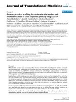
A calibration grating with a step height of 25 nm was used as the sample. A line trace
with constant scan speed of 30 µm/s is shown in Figure 1a. A typical scan has a
parachuting over a downward step and а peak over an upward step.
The time constant of the implemented dynamic controller is four times decreased in
the parachuting region. Figure 1b shows a scan line trace using the algorithm of the
dynamic controller. There is practically no parachuting, as shown in the figure.
However, the peak over the upward step stayed. In addition, there formed another
peak due to a significant increase in the error signal of the loop control after the probe
reached the bottom after a downward step. It was decided to reduce the scanning
speed in this region.
Figure 1c shows the line over a downward step trace in the case of a dynamic control
and over an upward step for a variable scanning velocity. For a detailed comparison,
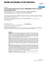
Figure 2 shows a part of the line traces (parachuting region) in the case of the usual
scanning with a constant speed of 30 µm/s and in the case of using dynamic control
with variable scanning velocity. For dynamic control, the length of parachuting is
reduced by three times.
- 6 -
Conclusions
The novelty of the presented scanning method consists of using a dynamic controller
on a downward step and variable scan speed on an upward step, with scan speed
determined by the magnitude of the error signal. As the experimental data on a
calibration grating show, assuming equivalent image quality, our method has an
advantage of up to three times in imaging speed.
Competing interests
The authors declare that they have no competing interests.
Authors' contributions
AVM and VVM contributed equally to this work. All authors read and approved the
final manuscript.
Acknowledgments
The authors would like to thank the Federal target programme Research and
Pedagogical Cadre for Innovative Russia for 2009-2013 (grant no 14.740.11.1449) for
providing financial support to this project.
References
1. Sulchek T, Yaralioglu GG, Quate CF: Characterization and optimization of
scan speed for tapping-mode atomic force microscopy. Rev Sci Instrum 2002,
73(8):2928-2936.
2. Kodera N, Sakashita M: Dynamic proportional-integral-differential
controller for high-speed atomic force microscopy. Rev Sci Instrum 2006,
77:083704.
3. Orun B, Necipoglu S, Basdogan C, Guvenc L: State feedback control for
adjusting the dynamic behavior of a piezoactuated bimorph atomic force
microscopy probe. Rev Sci Instrum 2009, 80: 063701.
4. Agarwal P, De T, Salapaka MV: Real time of probe-loss using switching gain
controller for high speed atomic force microscopy. Rev Sci Instrum 2009,
80:103701.
5. Zhao B, Howard-Knight JP, Humphris ADL, Kailas L, Ratcliffe EC, Foster SJ,
Hobbs JK: Large scan area high-speed atomic force microscopy using a
resonant scanner. Rev Sci Instrum 2009, 80:093707.
6. Fleming AJ, Kenton BJ, Leang KK: Bridging the gap between conventional
and video-speed scanning probe microscopes. Ultramicroscopy 2010,
110(9):1205-1214.
7. Zhang Y, Fang Y, Yu J, Dong X: Note: a novel atomic force microscope fast
imaging approach: variable-speed scanning. Rev Sci Instrum 2011, 82:056103.
- 7 -
8. Useinov A, Gogolinskiy K, Reshetov V: Mutual consistency of hardness
testing at micro- and nanometer scales. Int J Mater Res 2009, 7:968.
Figure 1. The line traces of the calibration grating with the step height equal to
25 nm. At a constant speed of 30 µm/s (a), with a dynamic control (b), and with a
dynamic control and at a variable speed (c).
Figure 2. Comparative line traces for a usual scanning (black) and with a
dynamic control (red).
Figure 1
Figure 2