báo cáo hóa học:" Joint cooperative relay scheme for spectrum-efficient usage and capacity improvement in cognitive radio networks" docx
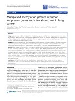
Bạn đang xem bản rút gọn của tài liệu. Xem và tải ngay bản đầy đủ của tài liệu tại đây (628.45 KB, 29 trang )
This Provisional PDF corresponds to the article as it appeared upon acceptance. Fully formatted
PDF and full text (HTML) versions will be made available soon.
Joint cooperative relay scheme for spectrum-efficient usage and capacity
improvement in cognitive radio networks
EURASIP Journal on Wireless Communications and Networking 2012,
2012:37 doi:10.1186/1687-1499-2012-37
Qixun Zhang ()
Zhiyong Feng ()
Ping Zhang ()
ISSN 1687-1499
Article type Research
Submission date 30 June 2011
Acceptance date 8 February 2012
Publication date 8 February 2012
Article URL />This peer-reviewed article was published immediately upon acceptance. It can be downloaded,
printed and distributed freely for any purposes (see copyright notice below).
For information about publishing your research in EURASIP WCN go to
/>For information about other SpringerOpen publications go to
EURASIP Journal on Wireless
Communications and
Networking
© 2012 Zhang et al. ; licensee Springer.
This is an open access article distributed under the terms of the Creative Commons Attribution License ( />which permits unrestricted use, distribution, and reproduction in any medium, provided the original work is properly cited.
Joint cooperative relay scheme for spectrum-efficient usage and
capacity improvement in cognitive radio networks
Qixun Zhang
∗
, Zhiyong Feng and Ping Zhang
Wireless Technology Innovation Institute (WTI), Key Laboratory of
Universal Wireless Communications Ministry of Education, Information
and Telecommunication Engineering of Beijing University of Posts and
Telecommunications (BUPT), Haidian Dist. Xitucheng Rd. Beijing
100876, P.R. China
∗
Corresponding author:
Email addresses
ZF:
PZ:
Abstract
In order to improve the efficiency of spectrum resource usage and the capacity of wireless networks, coop erative relay
techniques which utilize the vacant spectrum of primary users for secondary users’ data transmission have been applied
in cognitive radio networks. Considering the dynamic time-varying vacant spectrum resources and achievable rate on
different channels at relay nodes (RN), the traditional fixed time slot allocation scheme for cooperative RNs has the
bottleneck for further improving the spectrum usage efficiency and system throughput. Therefore, the joint cooperative
relay scheme with RN selection, channel allocation and dynamic time slot allocation (DyTSA), is designed to increase
the spectrum usage efficiency and system capacity by dynamic tuning DyTSA ratio to adapt to the changing radio
environment in multiple RNs serving multiple destinations scenario. Propositions of the proposed scheme are proved
theoretically by closed-form solutions. Numerical results verify the effectiveness and correctness of the proposed scheme.
Keywords: coop erative relay; cognitive radio networks.
1 Introduction
Based on measurement results unveiled by Federal Communications Commission (FCC) reports in [1,
2], precious radio spectrum resources are underutilized and a large number of spectrum holes exist
under traditional fixed spectrum assignment rules, which grant exclusive access to primary users (PU)
and pay little attention to spectrum usage efficiency. Considering the changing radio environment and
low spectrum usage efficiency, cognitive radio (CR) [3] technologies have been introduced with flexible
spectrum assignment schemes to improve the spectrum usage efficiency. Furthermore, based on software-
defined radio (SDR) [4] and CR [3] technologies, novel cognitive techniques with multi-domain radio
environment cognition, autonomous decision making, self-reconfiguration, and intelligent learning abilities
are proposed to improve both the spectrum usage efficiency and end-to-end (e2e) network performance
in cognitive radio networks (CRNs) [5].
However, challenges and problems on how to allocate spectrum to different secondary users (SU) with
unbalanced spectrum resources and user demands in CRNs still exist which attract many attentions in
recent research studies. By using vacant spectrum resources of PU for SU data transmission, cooperative
relay technique, which utilizes the resource-rich nodes to serve the resource-starving nodes as a relay,
has been considered as one of the key technologies to improve spectrum usage efficiency and enhance
system throughput in CRNs. In the literature, many research works have been conceived on cooperative
relay techniques in CRNs for spectrum efficiency enhancement. In [6], the cooperative spectrum sensing
techniques are used to enhance the reliability of detecting PU in CRNs, and a cognitive space-time-
frequency coding technique has been presented to adjust its coding structure by adapting itself to the
dynamic spectrum environment. And the outage performance of relay-assisted cognitive wireless relay
network is evaluated and quantified within the peak p ower constraints for spectrum sharing in [7]. Besides,
the stable throughput techniques are designed in [8] by using SU as a relay for PU link, whose benefits
depend on the network topology.
Furthermore, the distributed relay node (RN) selection and routing scheme is proposed with better
system coverage and spectrum efficiency compared to the centralized scheme in [9,10]. Based on buyer and
seller game model, the distributed RN selection and power control algorithms have been designed in [11]
to decrease the signalling cost in traditional centralized resource allocation scheme. Moreover, the joint
RN assignment and flow routing optimization scheme has been proposed by using novel components to
speed-up computation time of branch-and-cut framework in multi-hop relay networks in [12]. Besides, the
linear marking mechanism based optimal RN assignment scheme has been designed with formal proof
of the linear complexity in [13]. Multi-hop relay routing strategies and the NNR and FNR strategies
are proposed in [14] to enhance the spectrum usage and e2e system performance in a two-dimensional
geometric network in Rayleigh fading channel. By introducing the pricing variables in OFDMA cellular
system, a utility maximization framework has been proposed in [15] for joint RN selection, power and
bandwidth allocation to optimize the physical-layer transmission strategies for user traffic demands. To
maximize the throughput of relay network, the throughput optimal network control policy has been
proposed in [16] to stabilize the network for any arrival rate in its stability region.
Due to equipment limitations in transceivers, RNs can not transmit and receive data on orthogonal
channel at the same time for concurrent sessions. Thus, the half-duplex method by transmitting and
receiving at different time slots for RNs is paid much attention for real implementation purposes. As
described in [17, 18], a centralized heuristic solution has been proposed to address the relay selection
and spectrum allocation problem under an infrastructure-based secondary network architecture in CRNs
to improve spectrum efficiency. However, the constrains assumed by existing works in [18] that the
transmission rate of each channel is identical and the time slot allocation scheme is fixed with half time
to receive and the other half to transmit are not always applicable in terms of the time-varying channel
condition in practical wireless network environment. Hence, how to achieve the high spectrum efficiency
and system throughput under the condition of variant achievable rate on different channels and different
user’s demands with coop erative relay in CRNs is still an open issue.
Therefore, the dynamic time slot allocation (DyTSA) scheme is proposed in this article by dynamic
tuning the time slots allocated on each relay link for receiving and transmitting, to improve spectrum
efficiency and system capacity. The proposed DyTSA scheme considers the match up of variant achievable
rate on different channels and user’s demands. In multiple RNs serving multiple destinations (MR-MD)
scenario, the DyTSA scheme is analyzed and proved thoroughly under different scenarios with closed-form
solutions. Moreover, the joint RN selection, appropriate vacant channel allocation and DyTSA scheme is
designed, which is also regarded as a cross-layer optimization solution. Numerical results with different
SU density conditions verify the performance improvement on system capacity and spectrum efficiency
in CRNs. The rest of the article is organized as follows. Section 2 describes the system scenario and
assumptions. Section 3 focuses on problem formulation. Propositions and proofs are described in Section
4. Section 5 describes the joint RN selection, channel allocation and DyTSA scheme. Section 6 focuses
on the analysis of simulation results. Finally, Section 7 conclude the article.
2 System scenario and assumptions
The centralized co operative relay scenario is shown in Figure 1 with the secondary access point (SAP)
serving each SU via a direct link in a cooperative manner. It is assumed that one destination node can
be served by multiple RNs and each RN can also serve several different destination nodes at the same
time. As proposed in [17], each SU can send or receive data on multiple channels simultaneously with
one CR equipment, but it cannot send and receive data simultaneously. Figure 2 depicts the flow of the
transmission process and the time slot allocation solution in MR-MD scenario on different channels using
graph theory [19], jointly considering both the channel allocation and the RN selection schemes.
3 Problem formulation
The CRN with relay links is denoted as a graph G = (V, E). V = {v
0
, v
1
, . . . , v
N
} is a set of N + 1 nodes
with v
0
as the SAP and v
i
(i = 0) as SU. E = {e
ij
} denotes the set of direct links between each pair of
nodes, where e
ij
= 1 denotes that direct link between v
i
and v
j
exists, and 0 otherwise. It is assumed
that the available spectrum resource is divided into K channels with equal bandwidth W and A = {a
k
i
}
denotes the set of available channel at each node, where a
k
i
= 1 means that channel k is available at v
i
.
R = {r
ij
}
N×N
denotes the set of relay relation between each pair of SUs except SAP, where r
ij
= 1
means that v
j
acts as a RN for v
i
, and 0 otherwise. X =
x
k
ij
denotes the set of channel allocation
on each link, where x
k
ij
= 1 depicts that channel k is allocated to link e
ij
for data transmission, and 0
otherwise. C =
c
k
ij
denotes the set of achievable rate between v
i
and v
j
on channel k with bandwidth
W and c
k
ij
c
k
ij
≥ 0
is calculated in (1). H =
h
k
ij
denotes the channel-state of different channels on
various links, where h
k
ij
means the channel-state information of channel k on link e
ij
, P denotes the
transmit power and N
0
as the background noise power.
c
k
ij
= W log
1 +
|h
k
ij
|
2
· P
N
0
(1)
There are two types of transmissions for cooperative relay in CRNs scenario: the direct transmission
(from SAP to the destination node) and the relay transmission (from SAP to the destination node via
the RN). Due to different channel conditions, the achievable rate on each link is not identical as assumed
in [18] by c and the fixed equal time slot allocation scheme is neither efficient nor applicable with different
achievable rates on different channels in dynamic changing wireless network environment. Therefore, the
DyTSA scheme, which allocates different length of time slots for receiving and transmitting at the RN
in terms of variant achievable rates on different channels and the demands from destinations, has been
proposed to improve the spectrum efficiency and maximize the system throughput. Suppose the time
frame of data transmission from SAP v
0
to the destination node v
j
via RN v
i
is denoted by T
s
, which
is divided into two time slots t
0i
and t
ij
for receiving and transmitting on two relay links in Figure 2,
where r
ji
= 1. α
ji
(0 < α
ji
< 1) denotes the DyTSA ratio for relay link from v
0
to v
j
via RN v
i
, where
α
ji
= t
0i
/T
s
and T
s
= t
0i
+ t
ij
. Also, D = {d
i
} denotes the transmission demand of v
i
, where d
i
≥ 0, ∀i.
The throughput of v
i
is denoted by θ
i
, which can be calculated in three scenarios below.
3.1 Scenario 1
Destination node v
i
has no relay link and is not acting as a RN either, which only receives data from
v
0
via direct link with r
ij
= 0 and r
ji
= 0, ∀j. The throughput of v
i
is depicted by
θ
i
in (2), where
C
0i
=
K
k=1
c
k
0i
x
k
0i
is the sum of achievable rate between v
0
and v
i
and d
i
is its demand.
θ
i
= min (C
0i
, d
i
) (2)
3.2 Scenario 2
Node v
i
acts as the RN between v
0
and v
j
with constraint that its demand is smaller than its achievable
rate as d
i
< C
0i
, where r
ji
= 1 and r
ij
= 0. The throughputs of its own data and relay data are depicted
by
θ
ji
and θ
R
ji
in (3).
θ
ji
= d
i
θ
R
ji
= α
ji
C
0i
− d
i
(3)
3.3 Scenario 3
Node v
i
acts as the destination node with multiple RNs v
j
(1 ≤ j ≤ N, j = i), and the throughput
of v
i
via v
j
is depicted by
θ
R
ij
, where r
ij
= 1 and r
ji
= 0. Besides, the throughput of the direct link
from v
0
to v
i
is depicted by
θ
D
ij
and the total throughput at node v
i
is depicted by
θ
ij
in (4), where
C
ji
=
K
k=1
c
k
ji
x
k
ji
.
θ
R
ij
= (1 − α
ij
)C
ji
θ
D
ij
= C
0i
θ
ij
=
θ
R
ij
+
θ
D
ij
(4)
In summary, the total throughput θ
i
for node v
i
can be calculated by (5) in [18].
θ
i
=
1 −
N
j=1
r
ij
1 −
N
j=1
r
ji
θ
i
+
N
j=1
r
ji
θ
ji
+
N
j=1
r
ij
θ
ij
(5)
4 Propositions and proofs
Considering the MR-MD scenario, five propositions and proofs are analyzed and proved below in detail,
including the calculation of DyTSA ratio α
ji
and the system throughput improvement of DyTSA scheme.
4.1 Proposition 1
Assume the RN v
i
serves n destinations {v
j
, v
j+1
, . . . , v
j+n−1
}. D = {d
i
} depicts the demand of node v
i
and C
ij
=
K
k=1
c
k
ij
x
k
ij
depicts the sum of the achievable rate between v
i
and v
j
. Due to the assumptions
that the RN could not receive and transmit simultaneously, the optimal ratio from v
i
to its multiple
destinations is depicted by α
i
in (6), where α
i
= α
qi
= t
0i
/T
s
, q ∈ {j, j + 1, . . . , j + n − 1}.
α
i
= α
qi
=
d
i
+
j+n−1
q=j
C
iq
C
0i
+
j+n−1
q=j
C
iq
(6)
Proof: For each relay link r
qi
= 1, where q ∈ {j, j + 1, . . . , j + n − 1}, the data transmitted from
v
0
to v
i
must equal to the total data received at destinations {v
j
, v
j+1
, . . . , v
j+n−1
} to maximize the
system throughput as
θ
R
i
=
j+n−1
q=j
θ
R
qi
. Based on the formulas in (3)–(4) where
θ
R
i
= α
i
C
0i
− d
i
and
θ
R
qi
= (1 − α
qi
)C
iq
, ratio α
i
is verified by (7), where C
0i
=
K
k=1
c
k
0i
x
k
0i
≥ 0, C
iq
=
K
k=1
c
k
iq
x
k
iq
≥ 0 and
C
0i
+
r+m−1
q=r
C
iq
= 0.
∵
θ
R
i
=
j+n−1
q=j
θ
R
qi
∵
θ
R
i
= α
i
C
0i
− d
i
∵
j+n−1
q=j
θ
R
qi
=
j+n−1
q=j
(1 − α
qi
)C
iq
= (1 − α
i
)
j+n−1
q=j
C
iq
∴α
i
C
0i
− d
i
= (1 − α
i
)
j+n−1
q=j
C
iq
∴α
i
=
d
i
+
j+n−1
q=j
C
iq
C
0i
+
j+n−1
q=j
C
iq
(7)
4.2 Proposition 2
For RN v
i
selection, it must confine to the condition that its demand is no bigger than its achievable rate
in (8).
0 ≤ d
i
≤ C
0i
(8)
Proof: Chosen as the RN v
i
, its achievable rate C
0i
will change to α
i
C
0i
based on the DyTSA
scheme, which should be no smaller than its demand d
i
as α
i
C
0i
≥ d
i
to fulfill the relay task to multiple
destinations as shown in (9), where C
0i
≥ 0,
j+n−1
q=j
C
iq
> 0 and C
0i
+
j+n−1
q=j
C
iq
> 0.
∵α
i
C
0i
≥ d
i
∴α
i
C
0i
− d
i
=
(C
0i
− d
i
)
j+n−1
q=j
C
iq
C
0i
+
j+n−1
q=j
C
iq
≥ 0
∴0 ≤ d
i
≤ C
0i
(9)
4.3 Proposition 3
The throughput of dynamic scheme for relay link is no smaller than that of the fixed scheme in [18] by
(10), where
i+m−1
r=i
θ
R
r
=
i+m−1
r=i
(α
r
C
0r
− d
r
) =
i+m−1
r=i
(1 − α
r
)
j+n−1
q=j
C
rq
,
j+n−1
q=j
θ
R−f ix
qr
=
min
C
0r
/2 − d
r
,
1
2
j+n−1
q=j
C
rq
, C
0r
≥ 0,
j+n−1
q=j
C
rq
> 0, C
0r
+
j+n−1
q=j
C
rq
> 0, 0 ≤ d
r
≤ C
0r
/2.
i+m−1
r=i
θ
R
r
≥
i+m−1
r=i
j+n−1
q=j
θ
R−f ix
qr
(10)
Proof: Let us define ∆ =
i+m−1
r=i
θ
R
r
−
i+m−1
r=i
j+n−1
q=j
θ
R−f ix
qr
and the validity of (10) transforms
to prove ∆ ≥ 0, which are proved by three cases below.
4.3.1 Case 1
When 0 ≤ C
0r
/2 − d
r
<
1
2
j+n−1
q=j
C
rq
, then C
0r
−
j+n−1
q=j
C
rq
− 2d
r
< 0 and
j+n−1
q=j
θ
R−f ix
qr
= C
0r
/2 − d
r
.
∵∆
1
=
i+m−1
r=i
(1 − α
r
)
j+n−1
q=j
C
rq
−
i+m−1
r=i
C
0r
2
− d
r
(11)
=
i+m−1
r=i
C
0r
− d
r
C
0r
+
j+n−1
q=j
C
rq
j+n−1
q=j
C
rq
−
C
0r
2
+ d
r
(12)
=−
i+m−1
r=i
C
0r
C
0r
−
j+n−1
q=j
C
rq
− 2d
r
2
C
0r
+
j+n−1
q=j
C
rq
> 0
∴∆
1
> 0
(13)
4.3.2 Case 2
When C
0r
/2 − d
r
>
1
2
j+n−1
q=j
C
rq
, then C
0r
−
j+n−1
q=j
C
rq
− 2d
r
> 0 and
j+n−1
q=j
θ
R−f ix
qr
=
1
2
j+n−1
q=j
C
rq
.
∵∆
2
=
i+m−1
r=i
(1 − α
r
)
j+n−1
q=j
C
rq
−
i+m−1
r=i
1
2
j+n−1
q=j
C
rq
(14)
=
i+m−1
r=i
C
0r
− d
r
C
0r
+
j+n−1
q=j
C
rq
j+n−1
q=j
C
rq
−
1
2
j+n−1
q=j
C
rq
(15)
=
i+m−1
r=i
C
0r
−
j+n−1
q=j
C
rq
− 2d
r
j+n−1
q=j
C
rq
2
C
0r
+
j+n−1
q=j
C
rq
> 0
(16)
∴∆
2
> 0 (17)
4.3.3 Case 3
When C
0r
/2 − d
r
=
1
2
j+n−1
q=j
C
rq
, then C
0r
−
j+n−1
q=j
C
rq
− 2d
r
= 0 and
j+n−1
q=j
θ
R−f ix
qr
= C
0r
/2 − d
r
=
1
2
j+n−1
q=j
C
rq
.
∵∆
3
=
i+m−1
r=i
(1 − α
r
)
j+n−1
q=j
C
rq
−
i+m−1
r=i
1
2
j+n−1
q=j
C
rq
(18)
=
i+m−1
r=i
C
0r
−
j+n−1
q=j
C
rq
− 2d
r
j+n−1
q=j
C
rq
2
C
0r
+
j+n−1
q=j
C
rq
= 0
(19)
∴∆
3
= 0 (20)
In summary, ∆ ≥ 0 is correct based on the proofs in (13)–(20), which also proves the proposition in
(10).
4.4 Proposition 4
The demand d
j
of destination node v
j
equals to the sum of data from both direct link and multiple relay
links, where d
j
= C
0j
+
i+m−1
r=i
θ
R
jr
. The demand of v
j
is depicted in (21).
d
j
= C
0j
+
i+m−1
r=i
(C
0r
− d
r
)C
rj
C
0r
+
j+n−1
q=j
C
rq
(21)
Proof: Under the assumption that the demand d
j
of destination node v
j
equals to the sum of data
from both direct link and multiple relay links, d
j
is verified in (25), where
θ
R
jr
= (1 − α
jr
)C
rj
and
α
r
= α
qr
=
d
r
+
j+n−1
q=j
C
rq
C
0r
+
j+n−1
q=j
C
rq
.
∵d
j
= C
0j
+
i+m−1
r=i
θ
R
jr
(22)
∴d
j
= C
0j
+
i+m−1
r=i
(1 − α
jr
)C
rj
(23)
∴d
j
= C
0j
+
i+m−1
r=i
1 −
d
r
+
j+n−1
q=j
C
rq
C
0r
+
j+n−1
q=j
C
rq
C
rj
(24)
∴d
j
= C
0j
+
i+m−1
r=i
(C
0r
− d
r
)C
rj
C
0r
+
j+n−1
q=j
C
rq
(25)
4.5 Proposition 5
The calculation formula of the throughput θ
i
for node v
i
, which is applicable in the scenario of one RN
serving one destination node in [18], is also applicable in the MR-MD scenario as shown in (5).
Proof: Under the scenario of MR-MD nodes, the sum of the relay links for destination node v
i
via RN
v
j
is larger than 1, where
N
j=1
r
ij
> 1. For destination node v
i
, its throughput is calculated as in (5),
which is proved by (29) based on (2) and (4), where
N
j=1
r
ij
> 1,
N
j=1
r
ji
= 0 and d
i
> C
0i
. Finally,
the throughput of v
i
equals to its demand d
i
via relay links.
∵θ
i
=
1 −
N
j=1
r
ij
1 −
N
j=1
r
ji
θ
i
+
N
j=1
r
ji
θ
ji
+
N
j=1
r
ij
θ
ij
(26)
∴θ
i
=
1 −
N
j=1
r
ij
θ
i
+
N
j=1
r
ij
θ
ij
(27)
∴θ
i
=
1 −
N
j=1
r
ij
C
0i
+
N
j=1
r
ij
θ
R
ij
+ C
0i
(28)
∴θ
i
= C
0i
+
N
j=1
r
ij
θ
R
ij
= d
i
(29)
5 Joint RN selection, channel allocation and DyTSA scheme
Based on the theoretical model and analysis of the throughput θ
i
for node v
i
in (5), the total throughput
of all nodes in CRNs is depicted by
N
i=1
θ
i
in (30). Considering the MR-MD scenario in CRNs, the
constraints in [17,18], where
N
j=1
r
ij
≤ 1, 1 ≤ i ≤ N and
N
i=1
r
ij
≤ 1, 1 ≤ j ≤ N, will not be satisfied
by all nodes. So by appropriately applying the joint RN selection, channel allocation and DyTSA scheme
(R, X, α), the maximal total system throughput can be achieved by using the max flow theory [19] as
shown in (35).
N
i=1
θ
i
=
N
i=1
1 −
N
j=1
r
ij
1 −
N
j=1
r
ji
θ
i
+
N
j=1
r
ji
θ
ji
+
N
j=1
r
ij
θ
ij
(30)
max
R,X,α
N
i=1
θ
i
(31)
s.t. r
ij
N
j
=1
r
j
i
= 0, 1 ≤ i ≤ N, 1 ≤ j ≤ N
(32)
r
ij
≤ e
ij
, 1 ≤ i ≤ N, 1 ≤ j ≤ N
(33)
N
e
ij
∈E
x
k
ij
≤ 1, ∀k
(34)
x
k
ij
≤ a
k
i
a
k
j
, ∀i, j, k (35)
The process of proposed joint RN selection, channel allo cation and DyTSA scheme takes six steps as
shown in Figure 3 and is depicted below in detail.
Step 1: Allocate available channels to direct links from SAP node v
0
to all SU nodes v
i
, (1 < i < N)
in the centralized cooperative scenario.
Step 2: Divide nodes into two categories: spectrum “rich” nodes (0 ≤ d
i
≤ C
0i
) as relay and “starving”
nodes (d
i
> C
0i
) as destination.
Step 3: Sort all “starving” destination nodes based on its resource starving intensity as depicted by
(d
i
− C
0i
) in descending order which is denoted by the set D = {v
i
|d
i
> C
0i
, 1 ≤ i ≤ N
strv
}, where N
strv
is the total number of starving nodes and (1 < N
strv
< N ).
Step 4: First, select the most “starving” node D
j
from set D as the destination node which need
RNs, where D
j
= {j|j = argmaxd
j
> C
0j
, 1 ≤ j ≤ N
strv
}. Second, apply the augmenting path algorithm
for max flow to select appropriate RN v
i
for destination node D
j
and allocate channel for relay data
transmission for D
j
. Third, based on the DyTSA scheme design optimal DyTSA ratio α
ji
between RN
v
i
and destination node D
j
. And the flow of original RN v
i
is depicted by f
0i
, where f
0i
= d
i
. Therefore,
the relay data from v
i
to D
j
via path P
j
is denoted by τ(P
j
), where τ(P
j
) = α
ji
C
0i
− f
0i
. By applying
the augmenting path algorithm, the flow for D
j
has been changed to f
i
, where f
i
= f
i
+ τ (P
j
). Finally,
delete node D
v
from the set D and update the order in “starving” destination set D.
Step 5: Check whether the set D is empty. If the “starving” destination set D = φ and augmenting
path exists, then go back to Step 4 to find the possible augmenting path for the existing “starving” nodes.
Otherwise, if D = φ or no possible augmenting path could be found, it means that all nodes’ demands
are satisfied or no more spectrum and link resources are available in CRNs, then go to Step 6.
Step 6: Stop the process and calculate the system throughput of all nodes
N
i=1
θ
i
.
6 Simulation results and analysis
6.1 Simulation setup
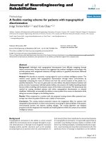
Considering the MR-MD scenario in CRNs as shown in Figure 4, parameters for simulation are shown
in Table 1 which are based on 3GPP Case 1 relay scenario [20]. The signal to noise ratio (SNR) of RN
and SU are depicted in (36)–(37). Suppose each user occupies only one resource block (RB) and the
achievable capacity of each RB in cooperative relay network is depicted by (38).
SNR
RN
(R
0i
) = P
SAP
− PL
RN
(R
0i
) − NP (36)
SNR
SU
(R
ij
) = P
RN
− PL
SU
(R
ij
) − NP (37)
c
ij
= log
2
1 + SNR(R
ij
)
(38)
6.2 Results analysis
Based on the parameters in Table 1, the SUs are randomly deployed in the simulation region with SAP
radius 100 m. The capacity of CRNs by using DyTSA and fix relay schemes are simulated and analyzed
with different SU density. As shown in Figures 5, 6, and 7, respectively, by dynamically tuning the DyTSA
ratio α
ji
to maximize the relay data transmission with different capacity on receiving and transmitting
links, the maximum system throughput of CRNs can be achieved by applying the DyTSA scheme in
contrast to the fixed scheme. Moreover, as the RNs increase, the vacant spectrum can be utilized much
more efficiently, which greatly improve the system capacity in CRNs.
Furthermore, the system capacity improvement by using DyTSA scheme is analyzed and compared
to the fixed scheme with the increase of DyTSA ratio α
ji
as shown in Figure 8. Results shown that the
system capacity of DyTSA scheme is no smaller than that of fixed scheme and the equilibrium point of
two schemes is α
ji
= 0.5. Apart from the equilibrium point α
ji
= 0.5, the system capacity of DyTSA
scheme is always bigger than that of fixed scheme as α
ji
increases, where 0 < α
ji
< 1. Two regions of
system capacity improvement are highlighted in Figure 8. Moreover, the fixed scheme is only effective
when 0 ≤ d
i
≤ C
0i
/2, while the DyTSA scheme is applicable in the general cases when 0 ≤ d
i
≤ C
0i
,
which is considered as a great improvement to the existing research works.
7 Conclusion and future work
As a novel solution to improve the spectrum efficiency and system capacity in CRNs, the DyTSA based
joint cooperative relay optimal scheme has been proposed and proved theoretically in this article. By
dynamically tuning the DyTSA ratio on different relay links, the system capacity has increased tremen-
dously comparing to the traditional fixed scheme. Moreover, by applying the joint RN selection, channel
The authors declare that they have no competing interests.
allocation and DyTSA scheme in MR-MD scenario, both the spectrum efficiency and system capacity
have been improved greatly and verified by numerous results.
Further studies on multi-hop cooperative relay schemes in CRNs need pay much attention on inter-
ference constraints from neighbor PUs and appropriate power control scheme for RNs.
Acknowledgements
The authors would like to thank the colleagues from the Wireless Technology Innovation Institute of
BUPT. This work was sponsored by the National Basic Research Program of China (2009CB320400),
National Key Technology R&D Program of China (2010ZX03003-001-01), National Natural Science Foun-
dation of China (60832009, 61121001) and Program for New Century Excellent Talents in University
(NCET-01-0259).
Competing interests
References
1. FCC, Spectrum Policy Task Force, Rep. ET Docket No. 02–135 (2002)
2. FCC, Facilitating opportunities for flexible, efficient and reliable spectrum use employing cognitive radio technologies:
notice of proposed rule making and order, FCC Document ET Docket No. 03–108 (2003)
3. J Mitola, Cognitive radio, Licentiate proposal, KTH, Stockholm, Sweden, 1998
4. J Mitola, Software Radios: Wireless Architecture for the 21st Century (Wiley, New York, 2000)
5. P Demestichas, G Dimitrakopoulos, J Strassner, D Bourse, Introducing reconfigurability and cognitive networks
concepts in the wireless world. IEEE Veh. Technol. Mag. 1(2), 32–39 (2006)
6. KB Letaief, W Zhang, Cooperative communications for cognitive radio networks. Proc. IEEE 97(5), 878–893 (2009)
7. Y Guo, G Kang, N Zhang, W Zhou, P Zhang, Outage performance of relay-assisted cognitive-radio system under
spectrum-sharing constraints. Electron. Lett. 46(2), 182–184 (2010)
8. O Simeone, Y Bar-Ness, U Spagnolini, Stable throughput of cognitive radios with and without relaying capability.
IEEE Trans. Commun. 55(12), 2351–2360 (2007)
9. AK Sadek, Z Han, KJR Liu, A distributed relay-assignment algorithm for cooperative communications in wireless
networks, in Proc. IEEE International Conference on Communications ICC’06, vol. 4, Istanbul, Turkey, July 2006,
1592–1597
10. AK Sadek, Z Han and KJR Liu, Distributed relay-assignment protocols for coverage expansion in cooperative wireless
networks. IEEE Trans. Mobile Comput. 9(4), 505–515 (2010)
11. B Wang, Z Han and KJR Liu, Distributed relay selection and power control for multiuser cooperative communication
networks using buyer/seller game, in Proc. IEEE INFOCOM, Anchorage, Alaska, 2007, pp. 544–552
12. S Sharma, Y Shi, YT Hou, HD Sherali, S Kompella, Cooperative Communications in multi-hop wireless networks:
joint flow routing and relay node assignment, in IEEE INFOCOM 2010, San Diego, CA, USA, May 2010, pp. 1–9
13. Y Shi, S Sharma, YT Hou, HD Sherali, S Kompella, SF Midkiff, Optimal relay assignment for cooperative commu-
nications, in Proc. of ACM MobiHoc, Hongkong, China, 2008, pp. 3–12
14. M Xie, W Zhang, K Wong, A geometic approach to improve spectrum efficiency for cognitive relay networks. IEEE
Trans. Wirel. Commun. 9(1), 268–281 (2010)
15. TC-Y Ng, W Yu, Joint optimization of relay strategies and resource allocations in cooperative cellular networks.
IEEE J. Sel. Areas Commun. 25(2), 328–339 (2007)
16. EM Yeh, RA Berry, Throughput optimal control of cooperative relay networks. IEEE Trans. Inf. Theory 53(10),
3827–3833 (2007)
17. Q Zhang, J Jia, J Zhang, Cooperative relay to improve diversity in cognitive radio networks. IEEE Commun. Mag.
47(2), 111–117 (2009)
18. J Jia, J Zhang, Q Zhang, Cooperative Relay for cognitive radio networks, in IEEE INFOCOM 2009, Rio de Janeiro,
Brazil, 19-25 April 2009, pp. 2304-2312
19. R Diestel, Graph Theory, 3rd edn. (Springer, Heidelberg, 2005)
20. 3GPP TR 36.814 V9.0.0, 3GPP TSG RAN (E-UTRA): Further advancements for E-UTRA physical layer aspects
(Release 9) (2010)
Table 1. Parameters for cooperative relay in CRNs
P
SAP
(dBm) 30
P
RN
(dBm) 23
System bandwidth BW (MHz) 10
Number of resource block (RB) 50
Bandwidth of each RB BW
RB
(MHz) 0.2
Path loss model from SAP to RN (R : km) PL
RN
(R) = 100.7 + 23.5log
10
R
Path loss model from RN to SU (R : km) PL
SU
(R) = 103.8 + 20.9log
10
R
Received noise power NP (dBm) 10log
10
(kTNFBW)
kT (mW/Hz) 1.3804 × 10
−20
× 290
NF (dB) 5
Distance between inter base station ISD (m) 1,732
Number of SU N
SU
10, 30, 50
Simulation time/sample 100
Figure 1. Scenario of DyTSA scheme in MR-MD scenario.
Figure 2. Flow of DyTSA scheme in MR-MD scenario.
Figure 3. Process of joint RN selection, channel allocation and DyTSA scheme.
Figure 4. Simulation scenario of MR-MD in CRNs.
Figure 5. Capacity improvement with N
SU
= 10 (DyTSA scheme vs. fix scheme).
Figure 6. Capacity improvement with N
SU
= 30 (DyTSA scheme vs. fix scheme).
Figure 7. Capacity improvement with N
SU
= 50 (DyTSA scheme vs. fix scheme).
Figure 8. Comparison of normalized system capacity with different DyTSA ratio α
ji
(DyTSA scheme
vs. fix scheme).
−1000
−800
−600
−400
−200
0
200
400
600
800
1000
Distance to SAP (m)
Distance to SAP (m)
SAP
Coverage of SAP
SU