báo cáo hóa học:" Research Article On Uplink Interference Scenarios in Two-Tier Macro and Femto Co-Existing UMTS Networks" pdf
Bạn đang xem bản rút gọn của tài liệu. Xem và tải ngay bản đầy đủ của tài liệu tại đây (783.87 KB, 8 trang )
Hindawi Publishing Corporation
EURASIP Journal on Wireless Communications and Networking
Volume 2010, Article ID 240745, 8 pages
doi:10.1155/2010/240745
Research Article
On Uplink Interference Scenarios in Two-Tier Macro and Femto
Co-Existing UMTS Networks
Zhenning Shi,
1
Mark C. Reed,
2, 3
and Ming Zhao
2, 3
1
Alcatel Lucent-Shanghai Bell, China
2
NICTA, Canberra Research Laboratory, Locked Bag 8001, Canberra ACT 2601, Australia
3
The Australian National University, Australia
Correspondence should be addressed to Mark C. Reed,
Received 4 September 2009; Revised 30 November 2009; Accepted 2 March 2010
Academic Editor: Holger Claussen
Copyright © 2010 Zhenning Shi et al. This is an open access article distributed under the Creative Commons Attribution License,
which permits unrestricted use, distribution, and reproduction in any medium, provided the original work is properly cited.
A two-tier UMTS network is considered where a large number of randomly deployed Wideband Code Division Multiple Access
(WCDMA) femtocells are laid under macrocells where the spectrum is shared. The cochannel interference between the cells may
be a potential limiting factor for the system. We study the uplink of this hybrid network and identify the critical scenarios that
give rise to substantial interference. The mechanism for generating the interference is analyzed and guidelines for interference
mitigation are provided. The impacts of the cross-tier interference especially caused by increased numbers of users and higher data
rates are evaluated in the multicell simulation environment in terms of the noise rise at the base stations, the cell throughput, and
the user transmit power consumption.
1. Introduction
Recent decades have witnessed an unprecedented growth in
the achieved data rate and the quality of service (QoS) in
wireless communications.
A coarse breakup on the increased capacity reveals that
most cellular throughput improvement comes from better
area spectrum efficiency. Mobile broadband communication
solutionswithhighspectralefficiency are needed for indoors
where demands for higher data rate services and better
coverage are growing, for example, residential or office
scenarios. It is difficult to provide this coverage and data
throughput by macro-cellular networks. This forms the basic
foundation that motivates the recent emerging femtocell
architecture. Femtocells are essentially an indoor wireless
access points for connectivity to the networks of wireless
cellular standards. It serves home users with low-power,
short-range base stations such as the 3GPP definition of
a Home NodeBs (HNB). By enhancing the capacity and
coverage indoors, where a majority of user traffic originates,
HNBs also bring substantial benefits to the macronetwork
as the macrocell resources can be redirected to outdoor
subscribers. In addition, femtocell deployment can bring
substantial cost savings to operators by reducing operational
costs (OPEX) and capital costs (CAPEX) as well as the churn
rate from subscribers.
The introduction of femtocells gives rise to a number of
technical challenges [1], for example, the IP interface to the
backhaul network, closed or open access, synchronization
and interference. Due to the scarcity of the radio spectrum
resources, femtocells are likely to share the same carriers
with the existing macrocells, which may cause interference
across the two cellular layers. In particular, operators have
concerns on the impact of femtocells onto the macrocells.
To this end, an in-depth analysis on interference problems
is needed. A comprehensive description of interference cases
that exist in the uplink and downlink of the two-tier
hybrid networks is given in [2]. These cases are conceptually
illustrated through the simple models consisting of a couple
of cells, and the analytical results of the basic scenarios are
summarized together with the guidelines for interference
mitigation. In the downlink, the deployment of femtocells
may create multiple dead zones in the macrocell. The
cochannel interference can be mitigated by using cognitive
radio and adaptive power management techniques in the
home base stations [2, 3].
2 EURASIP Journal on Wireless Communications and Networking
In [4], a stochastic geometry model is employed to
characterize the air interface statistics in large-scale hybrid
networks, and Poisson-Gaussian sources are used to approx-
imate the interference within and between the tiers. This
approach allows the analysis to reflect the randomness of the
network. However, it is assumed in [4] that users in both
layers are under good coverage from their serving nodes,
which may not always be the case in realistic scenarios. In [5]
the femtocell capacity is shown in terms of the deployment of
femtocells, user distribution in femtocells as well as the user
excursion into neighbouring femtocells. In [6], the authors
study the effect of access policy on a macro cellular network
with embedded femtocells and suggest it should be adaptive
to specific scenarios and the perspective of all participants in
the system. It is found that by allowing a limited access to the
femtocells, the similar QoS level to that of the macro-only
scenario and much improved throughputs for all subscribers
can be achieved.
In [1], a femtocell configuration is shown to improve the
spectral efficiency of the network by orders of magnitude. In
[4], time hopping and directional antenna are proposed to
interference and further increase the capacity. A utility-based
power control method is proposed in [7] to mitigate the
cross-tier interference at the expense of a reasonable degra-
dation in the femtocell SINR. Nevertheless, it is based on the
assumption that the user penetration between layers is not
severe, that is, the users from one layer are not likely to come
within the vicinity of the NodeBs in the other layer and cause
substantial cross-tier interference. We note that if open access
is not supported for femtocells, user penetration inevitably
leads to an adverse condition for both femtocells and
macrocells. This calls for more research efforts in this area.
In this paper, we consider the uplink (UL) interfering
scenarios in the WCDMA femtocells with a macronetwork
overlay. The motivation for focusing on the uplink is
to better understand the noise-rise onto the macro base
stations and to understand what improved sensitivity at
the femtocell would mean to overall system performance.
To be in line with the current approach, we consider the
closed subscriber group (CSG) femtocell where the home
network is only accessible by a limited number of subscribers.
We assume a shared carrier for femto and macronetworks,
whereby the options of frequency and time hopping [4]and
dedicated carriers for femtocells are excluded. In particular,
two interference scenarios that UE penetration triggers in
the uplink, that is, what we refer to as the “Kitchen Table
problem” and “Backyard problem”, are studied to show the
cases that may cause a service disruption in the system of
interest. The analysis is conducted in a large-scale system
and takes into account other interfering sources [2]in
the network air interface. It also provides a comprehensive
study on how different interfering causes are inextricably
linked and take effects jointly. In this paper, the interference
mitigation techniques are considered to enable the network
operation even in the extreme cases.
The paper is organized as follows. In Section 2,twoup-
link interfering scenarios under consideration are described,
together with, the system parameters used in the system
analysis. In Section 3, the noise rise at macro NodeBs (MNB)
Macro2
Femto1
UE1
UE2
Interference
(a) Kitchen Table UE
Macro2
Femto1
UE1
UE2
Interference
(b) Backyard UE
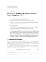
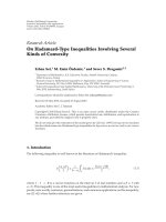
Figure 1: Illustrative examples of two interfering scenarios in the
femtocell uplink.
is formulated and serves as a basis to separate the interfering
sources in the uplink. A number of interference management
techniques tackling the intercell and intracell interference
are then presented. In Section 4, system simulation results
are presented for suburban and urban scenarios to show
the interference effect on both the macro and femto layers.
Conclusions are summarized in Section 5.
2. System Model
2.1. Uplink Interfering Scenarios. Femtocells can support
high data rate services since the transmitter and receiver
are very close to each other and the resultant transmit
power is very low. However, this is no longer the case
when uncoordinated subscribers come to the vicinity of
the femtocell HNB. Diagram in Figure 1(a) illustrates the
scenario [2], where one macrocell and one femtocell co-
exist. Subscriber UE 1 is connected to the macrocell and
termed as the MUE, while subscriber UE 2 camps on the
femtocell and is referred to as the HUE. In this case, UE 1
enters into the household of the femtocell and causes strong
interference at HNB. At the (macro-) cell-edge location, the
interference becomes overwhelming as UE 1 transmit power
EURASIP Journal on Wireless Communications and Networking 3
is close to the maximum. This MUE causes the case, what
we call the Kitchen Table user (KTU) problem, where on
a kitchen table there could be both femto connected and
macro connected terminals. The macroconnected terminals
generate high interference due to the short distance between
them and the affected HNB.
The other scenario that causes noticeable uplink inter-
ference takes place when the HUE, that is, the users on the
femtocells, moves outside the household and continues the
femtocell service. Since the femto-connected user’s signal
now penetrate through the home residence, the HUE has
to transmit at a much higher power level than its indoor
counterparts. Classified as Scenario D in [2], we name this
user the Backyard User (BYU), and thus it generates the BYU
problem discussed in the paper. In Figure 1(b),bothusers
are connected to the femtocell, while UE 2 is inside the house
where the HNB coverage is good, and the other user, UE
1, is on the edge of the HNB coverage. UE 2 introduces
significant interference onto the Macro layer as well as to
neighbouring femtocells. In the cases where the femtocell
under consideration is close to the macrocell site, the noise
rise from UE 1 at the macro NodeB can be significant.
The KTU and BYU problems are two extreme cases
which may bring a disruption to the network service.
Although the primary victims of BYU and KTU scenarios
are the macro NodeB (MNB) and HNB, respectively, our
analysis shows that they are not independent but rather
inextricably linked, that is, one problem may enhance the
other. To understand this, let us look at an example where
the KTU and BYU problems happen simultaneously in the
femtocell, that is, there is a KTU close to the HNB while an
HUE outside of the house. In this case, the backyard HUE has
to further increase the power to overcome the interference
from the uncoordinated KTU. By doing so, it aggravates the
resource constraint in the uplink by adding more interference
at the macrobase station. Keeping this in mind, our study
aims to reveal the joint effect of these two issues, rather than
study them in separate scenarios.
2.2. System Simulation Assumptions. In this section, we
introduce the cellular environments where the uplink of the
hybrid network is studied. In Ta ble 1 , simulation parameters
of macrocells and femtocells are specified for suburban and
urban scenarios, respectively. The following assumptions are
stipulated in the system model:
(i) A three-tier 37 macro-cell structure is considered for
macronetwork where the macro NodeB of interest is
in the center and the frequency reuse factor is one.
(ii) All mobiles terminals are uniformly distributed in the
macrocells and femtocells, except that the outdoor
HUEs are on the femtocell boarder and at the nearest
side to the macrocell base station.
(iii) Directional antennas (sectorisation) are employed at
the macro base stations to increase the capacity while
omni-directional antennas are employed at the femto
HNBs.
(iv) The residential home penetration loss is 10 dB.
(v) Outdoor HUE penetration, that is, the percentage of
BYUs in the total population of HUEs, conforms to
those in [8].
(vi) Indoor MUE penetration refers to the percentage of
the KTUs in the total population of MUEs.
(vii) For macrocell service, only voice calls are used. While
for femto cells, three types of services are specified in
Ta bl e 2, ranging from the voice call to medium data
rate services.
(viii) Perfect power control is assumed at both macro base
stations and femtocell HNBs (Here HUE power is
determined to guarantee the assigned data service
under the power cap.).
3. Uplink Interference Management
As the uncoordinated UEs get close to nonserving NodeB,
they typically introduce at these NodeBs interference that
is significant w.r.t. the noise floor. Interference from a few
such aggressors may cause service disruption in the affected
cell. Even in cases where the services can be maintained,
it is achieved at the cost of higher power consumption for
UE. This in turn would deteriorate the services in other
neighbouring NodeBs, that is, it forms a closed loop with
positive feedback that makes the situation even worse. In this
paper, the cost function to optimize is the Rise over Thermal
(RoT) at macro base stations and HNB.
Assuming that the transmitted signals over the wireless
link are primarily subject to the propagation loss, and that
the downlink pathloss is the same as that in the uplink, the
RoT at macro NodeB caused by a scheduled HUE is given by
[9] as follows:
RoT
MNB
= Δ
P
+ Δ
N
+ ρ
HNB
+RoT
HNB
+ τ − Δ,
(1)
where Δ
P
= P
HNB,max
− P
MNB,max
is the difference between
NodeB transmission power, Δ
N
= N
HNB
− N
MNB
is the
difference on the noise figures of NodeBs, ρ
HNB
is the
required carrier-interference-ratio (CIR) at HNB, RoT
HNB
is
the receive interference (w.r.t. to noise floor) at HNB, τ is
the average transmission power increase due to fast power
control and Δ denotes the coverage difference at the position
of HUEs between femto and macro cells. The RoT of HNB
caused by an uncoordinated MUE (In this paper, we focus
on the noise rise caused by femto-to-macro interference or
vice versa, to highlight the impacts of femto deployment as
well as simplify the analysis.) is given by
RoT
HNB
= P
MUE
−L
MUE-HNB
−N
HNB
,
(2)
where P
MUE
is the transmission power of the MUE and
L
MUE−HNB
is the pathloss between the MUE and the affected
HNB. RoT leads to degradation in the receiver sensitivity,
hence needs to be minimized. In the following, we present
a number of techniques that mitigate the RoTs at NodeBs.
3.1. HNB Power Management. Typically good femtocell
downlink coverage can be achieved more easily when
4 EURASIP Journal on Wireless Communications and Networking
Table 1: System Parameter for Macro and Femtocells.
Suburban
scenario
Urban
scenario
Macrocell parameters
Macrocell Radius 1 km 500 m
Max. Macro NB Transmit
Power
43 dBm 43 dBm
Maximum Indoor MUE
(Kitchen Table User)
Transmit Power
24 dBm 18 dBm
Maximum Outdoor MUE
Transmit Power
14 dBm 8 dBm
Number of Sectors per Cell 3 6
Data Rate per MUE 15 kbps 15 kbps
Spreading Factor for MUE 128 128
Number of MUEs per km
2
26 229
Relative power of control
channel
−6dB −6dB
Asynchronous Uplink Yes Yes
Duty cycle for voice call 100% 100%
MUE Indoor Penetration 10% 10%
Femtocell parameters
Femtocell Radius 15 m 10 m
Max.HNBTransmitPower 20dBm 20dBm
Shielding (Penetration)
Loss
10 dB 10dB
Area percentage occupied
by HNB
2.4% 3%
Number of HUEs per HNB 2 2
Number of HUEs per km
2
68 190
Spreading factor for HUE variant variant
Duty cycle for data service 100% 100%
HUE Outdoor Penetration 20% 10%
HNB RoT threshold 12 dB 12dB
Propagation loss model
Macrocell
133 + 35 log
10
(d)dB
Femtocell
98.5+20log
10
(d)dB
Voice 15 kbps 15 kbps
Low Rate Service 120 kbps 60 kbps
Medium Rate Service 360 kbps 120 kbps
femtocell location approaches the macrocell border. In these
cases, a low transmit power by HNB suffices for the range of
a normal residence. On the other hand, the HNB coverage is
weak when the femtocell is close to the macro cell site due to
the strong macro downlink interference. A fixed HNB power
setup is suboptimal as it fails to provide constant femtocell
coverage across the macrocell, and it may introduce excessive
interference to the macrocell.
Adaptive HNB power is an effective means to minimize
the impact on the macrocell while keeping a satisfying
coverage within the femtocell. To this end, common pilot
channel can be used to measure the downlink channel and
an appropriate HNB power is determined. In [3], a mobility
event-based algorithm is used in managing HNB pilot power
to minimize the unwanted handover events of UEs when
HNB is in operation. Employment of the adaptive scheme
substantially reduces the HNB power consumption, which
corresponds to a reduction on Δ
P
in (1)andleadstoa
decreasing RoT
MNB
in turn.
Since femtocell deployment is not planned but rather
random in nature, zero-touch self-configuration is preferred.
To this end, a Network Listen Mode (NLM) is needed at HNB
to scan the network air interface [10].
3.2. Handover Outdoor HUE to the Macrocells. Outdoor
HUEs may generate severe inference at the macro base
stations. This can be clearly seen in (1) where as the HUE
moves to the femto cell border, the downlink coverage by
the macro NodeB can be much better than that of the
serving HNB, that is, Δ is small, while the resultant RoT
at MNB increases. A viable solution is to handover the
HUE to the macro layer. On one hand, this removes the
outdoor HUEs from the serving HNB, and relieves the
Backyard Problem. On the other hand, HUEs added onto
the macro layer consume the system resources that would
be otherwise allocated to MUEs. HUE handover techniques
can be determined by evaluating the signal quality of the
downlink CPICH channel of the serving HNB, w.r.t. that
from nearby macro base stations.
3.3. Inter-Frequency Switch for MUEs in the Dead Zone.
Femto deployment generates coverage holes called dead
zones inside the macrocell. Macro UE in the dead zone
undergoes tremendous cross-layer interference from the
HNBs in the downlink and may experience a service dis-
ruption. On the other hand, macro UE inside the dead zone
causes severe interference to the femtocell uplink transmis-
sion. This can be observed in (2) where RoT
HNB
dramatically
increases when L
MUE-HNB
is small. In this case, switching
of the MUEs inside the dead zone, that is, Kitchen Table
UEs, to another carrier or Radio Access Technique (RAT)
can effectively mitigate the problem in both femtocells and
macrocells, given that the operator has alternative carriers.
3.4. Adaptive Uplink Attenuation. On average, the transmis-
sion power of femto HUEs is below that of macro UEs,
due to the much shorter transmission range. Nevertheless,
the dynamic range of a receiver frontend (RF) is large
at the HNB and can cope with strong interference from
uncoordinated UEs in extreme cases. If the noise figure N
HNB
is fixed, the interference caused by uncoordinated Kitchen
Table MUE results in a substantial noise rise RoT
HNB
. This
in turn reduces the uplink throughput (number of users)
that the HNB can support significantly [8, 11]. To resolve
the problem, an additional UL attenuation gain is proposed
for the receiver RF at the HNB to deal with the surging
interference [8, 11].
We study the problem by assuming that the femtocells
affected by Kitchen Table User can be anywhere, rather than
EURASIP Journal on Wireless Communications and Networking 5
Table 2: Impact on macrocell throughput and range.
Data rate Receiver mode
Macro rate reduction in [%] Increase in the number of macro-BS in [%]
Urban Suburban Urban Suburban
Case 1 Medium Conv. 3.33.70.40.2
Case 2 Medium Conv. 40.025.950.915.9
Case 2 Medium Adv. 10.03.70.40.2
Case 3 Voice Conv. 3.33.70.40.2
Case 3 Low Conv. 13.37.40.40.2
Case 3 Medium Conv. 53.337.087.628.5
Case 4 Mix Conv. 30.018.525.17.6
Case 4 Mix Adv. 10.03.70.40.2
0
0.1
0.2
0.3
0.4
0.5
0.6
0.7
0.8
0.9
1
CDF
0 5 10 15 20 25 30
Additional UL attenuation (dB)
UL attenuation distribution in the presence of KTU
Suburban scenario
Urban scenario
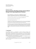
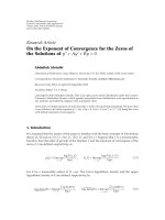
Figure 2: Distribution of adaptive UL attenuation gain when there
is Kitchen Table MUE.
on a few isolated points in the macro cell [2]. Depending
on their positions in the macrocell, the effect of Kitchen
TableMUEsonthefemtocellisdifferent, reflected by the
distribution of the UL attenuation gain over a wide range.
Figure 2 shows the distribution of the UL attenuation gain
employed at the home NodeB RF frontend. It is observed
that in suburban scenarios the attenuation gain can be as
high as 30dB, while in more than 90% of the cases the
HNB receiver needs to attenuate the incoming signals by
more than 15 dB. This number drastically decreases in urban
areas, where only a marginal percentage of HNBs need to
execute an additional attenuation gain of 15 dB. By doing so,
the extravagant noise rise caused by the nonconnected UEs
can be effectively controlled within the system-defined RoT
threshold, which is marked as the red dashline in Figure 3.
It should be noted that using a large attenuation gain may
increase the battery drain of the femto-connected terminals,
reduce femtocell range, and cause additional interference
onto neighboring femtocell HNBs and macro base stations.
0
0.2
0.4
0.6
0.8
1
CDF
0 5 10 15 20 25 30 35 40
Noise rise at HNB (dB)
RoT
HNB noise rise distribution for suburban scenario
(a)
0
0.2
0.4
0.6
0.8
1
CDF
0 5 10 15 20 25 30 35 40
Noise rise at HNB (dB)
RoT
HNB noise rise distribution for urban scenario
Vo ice, w i t h AG C
Low rate, with AGC
Vo ice, w o AGC
Low rate, wo AGC
(b)
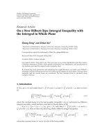
Figure 3: Distribution of rise over thermal (RoT) in a femtocell
with nonconnected UE penetration.
Therefore, it should be adaptive to the interference in the
radio environment and applied only when it is necessary.
3.5. Downgrade Service of HUE. Under the strong interfer-
ence from the Kitchen Table MUEs, the HUE can reduce the
data rates of its services to relax the power requirements. This
mechanism eliminates the unnecessary interference to other
cochannel users but will compromise data throughput. In
this paper, we let HUEs tune to the service of the highest
supportable data rate if they can not achieve the target
data rate. Moreover, HUE transmission power is capped at
a maximum power of 21 dBm to avoid creating excessive
interference.
6 EURASIP Journal on Wireless Communications and Networking
0
0.1
0.2
0.3
0.4
0.5
0.6
0.7
0.8
0.9
1
CDF
04020 40 60 80 100 120 140
Data rates (kbps)
Outdoor HUE throughput distribution (suburban scenario)
Vo ice, w i t h K TU
Low rate, with KTU
Medium rate, with KTU
Vo ice, w o K T U
Low rate, wo KTU
Medium rate, wo KTU
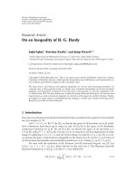
Figure 4: Distribution of outdoor HUE throughput in the presence
of Kitchen Table MUEs.
3.6. Improved Femtocell Receiver Sensitivity. Application of
advanced methods to improve the femtocell sensitivity will
reduce the transmit power from Femto-connected UEs.
Different techniques can be used to achieve this including
antenna diversity, interference cancellation, enhanced signal
processing in synchronization, and channel estimation and
equalization [12–14]. This not only enhances the perfor-
mance in the femtocell, but also reduces the interference
introduced to the macro layer as will be seen in the presented
results.
4. Simulation Results
In this section, simulations are conducted in a femto-macro
hybrid network specified in Section 2 to show the impacts
of the femtocell deployment. The direct consequence of the
Kitchen Table problem is to generate substantial noise rise at
the affected HNBs and degradation in the HUE throughput.
The increase in the HUE transmit power is shown as a
result of the desensitized HNB receiver. The impact in the
macro layer is studied by observing the noise rise and data
throughputs in the macrocell. Unless specified otherwise, we
use the parameters in Ta bl e 1 in all simulations. Adaptive
power management is assumed at the home NodeBs such
that a constant coverage is maintained for femtocells. The
uplink attenuation technique in Section 3.4 is employed to
mitigate the impact of the severe cross-tier interference.
Due to the strong interference of a macro-connected user,
the Kitchen Table problem deteriorates the femtocell user
performance significantly. Figures 4 and 5 show the rate
distribution of three types of HUE services when there is
Kitchen Table MUE against that in the absence of Kitchen
Table MUEs. In suburban areas, it can be seen that for low
data rate, around 35% of outdoor HUEs are served below
the target rate of 60 kbps, while the ratio jumps to 68%
0
0.1
0.2
0.3
0.4
0.5
0.6
0.7
0.8
0.9
1
CDF
0 50 100 150 200 250 300 350 400
Data rates (kbps)
Indoor HUE throughput distribution (suburban scenario)
Vo ice, w i t h K TU
Low rate, with KTU
Medium rate, with KTU
Vo ice, w o K T U
Low rate, wo KTU
Medium rate, wo KTU
Figure 5: Distribution of indoor HUE throughput in the presence
of Kitchen Table MUEs.
−25
−20
−15
−10
−5
0
5
10
15
Average HUE power (dBm)
Suburban area, outdoor HUE = 20%
Vo ice
Low rate
Medium rate
Indoor HUE, KTU
= 0%
Indoor HUE, KTU
= 10%
Out HUE, KTU
= 0%
Out HUE, KTU
= 10%
Figure 6: Average transmit power of HUEs in suburban scenario.
for medium data rate, reflecting a drastic degeneration in
the uplink throughput. On the other hand, target rates can
be easily achieved in cases where there is no Kitchen Table
User. For indoor HUEs, the relative reduction is smaller in
the presence of Kitchen Table UE. Nevertheless, the ratio
of services staying below the target rate is still 57% for the
medium rate service.
There is typically enough headroom in the femtocell
UE transmit power due to the short transmission range.
However, this is no longer the case when the Kitchen Table
problem or Backyard problem occurs. Figure 6 shows the
average transmission power of indoor and outdoor HUEs
EURASIP Journal on Wireless Communications and Networking 7
−25
−20
−15
−10
−5
0
5
10
15
Average HUE power (dBm)
Urban area, outdoor HUE = 10%
Vo ice
Low rate
Medium rate
Indoor HUE, KTU
= 0%
Indoor HUE, KTU
= 10%
Out HUE, KTU
= 0%
Out HUE, KTU
= 10%
Figure 7: Average transmit power of HUEs in urban scenario.
in the suburban scenario. It can be seen that even though
the outdoor HUEs are on services of lower data rates, their
power consumption is typically 5
∼15 dBm higher than that
of the indoor counterparts. This can be explained by noting
that outdoor HUEs have to use extra transmit power to
compensate for the more significant pathloss, including the
building penetration loss. It is also observed that the presence
of Kitchen Table MUEs leads to a drastic increase on the
power consumption for affected femtocell users. Figure 7
shows the average power for HUEs in urban scenario, which
has a similar trend to that in suburban scenario.
The Kitchen Table problem is considered as the worst
scenario for the HNB where the uncoordinated MUEs
introduce significant interference into the femtocell uplink.
Nevertheless, from (1) it can be seen that a noise rise in the
femtocell can also affect the macro-NodeB, since HUEs in
the femto cells need to boost up their transmission power
to improve the received signal quality at the HNB. In [2],
this is classified as an undesired UE noise rise at non-serving
NodeBs. To clearly show the impacts of HUEs, jointly with
Kitchen Table and Backyard problems on the macrocell, four
test cases are defined as follows.
(i) Case 1. No Kitchen Table or Backyard Problem.All
HUEs stay inside their homes and are under good
coverage of the serving HNB, while all MUEs are
outside the femtocell households.
(ii) Case 2. Backyard Problem Only. A number of HUEs
are on the femtocell edge (specified for suburban and
urban scenarios), while macro UEs stay clear of the
femtocell households.
(iii) Case 3. Joint Kitchen Table and Backyard Problems.
A number of HUEs are at the femtocell edge and
some MUEs are inside the units with femtocells. The
percentage of outdoor HUEs and indoor MUEs is
specified in Tab le 1 .
(iv) Case 4. Mixed Service. The break up of indoor
and outdoor HUE services is 70%, 20%, and 10%
for voice calls, low rate services, and medium-rate
services, respectivlely.
In the simulations, a baseline system equipped with con-
ventional receiver techniques is considered. Ta bl e 2 includes
the reduction in macrocell throughput due to the introduc-
tion of femtocells. It can be seen from that in Case 1, with
neither Kitchen Table nor Backyard problems, interference
from femtocells is tolerable and causes a marginal loss in
the macrocell. The rate loss is below 5% in both urban and
suburban scenarios.
In Case 2, which embodies the Backyard User problem
only, the macro throughput loss increases substantially,
especially for services of higher data rates. The rate reduction
caused by medium rate femtocell services is 40% and 26% for
urban and suburban scenarios, respectively. Results for voice
and low data rates show marginal performance degradation
in Cases 1 and 2, and hence omitted from the table.
Case 3 takes into account both Kitchen Table and
Backyard problems, hence represents the worst scenario for
the hybrid radio network. While a rate loss of no more
than 15% is observed in macrocell for low rate femtocell
services, the throughput compromise jumps to 53% and
37% for medium rate services, in suburban and urban
scenarios. It indicates that the capacity increase in femtocells
may trigger substantial macrocell performance degradation
if severe Kitchen Table and Backyard problems exist.
Case 4 represents a service portfolio that is akin to
the realistic traffic in the femtocell. In this case, macrocell
throughput reduction can be up to 30% and 18% in urban
and suburban scenarios, while improvements in receiver
sensitivity are able to mitigate the problem by a great extent.
We consider advanced techniques that can improve the
sensitivity of the single user decoding chain by a couple of
dBs and are able to cancel 80% of the intracell interference
(In [14], it is shown that around 2 dB improvement in
receiver sensitivity can be achieved for a moderately loaded
UMTS by employing data-aided channel estimation. Using
the soft interference cancellation (SIC), 80% of interfering
power can be removed if the BER in the previous decoding
iteration is below 0.05).
To better understand the consequence of the femtocell
coexistence onto the macrocell, the increase in the MNB
number is included in the right-most columns in Ta b le 2 .
It can be seen that for Case 4 traffic, much more oper-
ator infrastructure is needed to maintain sufficient QoS
with conventional receiver techniques. While the degrada-
tion becomes negligible if advanced signal processing is
employed.
It is also observed that compared to the macrocells in
suburban areas, macrocells deployed in the urban scenario
are more subjected to the interference from the femtocells.
This is because the urban macrocells have a much smaller
range and the base station is closer to the femtocells.
Moreover, due to the higher density of femtocell populations
and the fact that the HUEs are more likely to be at the
cell edge (refer to Ta bl e 1), urban macro base stations are
8 EURASIP Journal on Wireless Communications and Networking
interfered by more users in the femto layer, especially those
causing strong interference.
5. Conclusion
The new wireless configuration using femtocells is an
appealing application to enhance the indoor service in
residential areas, hot spots, and macro cellular environments,
while reducing operator costs. Due to the randomness
of femtocell deployments, it is crucial to understand the
impacts of femtocells on the existing networks and try to
minimize these effects. In this paper, we consider a hybrid
network with coexisting femto and macrocells, and provide
a comprehensive study on the impacts of deploying a large
number of femtocells in the shared spectrum with macro
cells. In particular, two severe interference scenarios caused
by penetration of nonconnected UE to the other layer are
analyzed. Our analysis considers a large cellular network and
discusses a number of interference management schemes to
improve the situation. We show through simulation that the
Kitchen Table problem is the worst case scenario and on
average 57% of indoor and 68% of outdoor HUEs cannot
achieve the target throughput. Due to such strong inter-
ference from uncoordinated MUE, the HUE consumes 5
∼
10 dB more power than it normally needs. Such HUE power
boosting also produces undesired noise rise at macro BS. Our
results show that up to 53% and 37% macrocell throughput
reductions are observed at macro BS in suburban and
urban scenarios, respectively. Together with these simulation
results, guidelines for minimizing the impacts of embedded
femtocells on the underlying macrocells are presented.
Acknowledgments
Z. Shi was with NICTA and affiliated with the Australian
National University when the work was done. He is currently
with Alcatel-Lucent Shanghai Bell. M. C. Reed and M. Zhao
are with NICTA and affiliated with the Australian National
University. NICTA is funded by the Australian Government
as represented by the Department of Broadband, Communi-
cations and the Digital Economy and the Australian Research
Council through the ICT Centre of Excellence program.
References
[1] V. Chandrasekhar, J. G. Andrews, and A. Gatherer, “Femtocell
networks: a survey,” IEEE Communications Magazine, vol. 46,
no. 9, pp. 59–67, 2008.
[2] “Interference management in UMTS femtocells,” Femto
Forum White Paper, December 2008.
[3] H. Claussen, L. T. W. Ho, and L. G. Samuel, “Self-optimization
of coverage for femtocell deployments,” in Proceedings of the
7th Wireless Telecommunications Symposium (WTS ’08),pp.
278–285, Pomana, Calif, USA, April 2008.
[4] V. Chandrasekhar and J. G. Andrews, “Uplink capacity and
interference avoidance for two-tier cellular networks,” in
Proceedings of the IEEE Global Telecommunications Conference
(GLOBECOM ’07), pp. 3322–3326, Washington, DC, USA,
November 2007.
[5] D. Das and V. Ramaswamy, “On the reverse link capacity of
a CDMA network of femto-cells,” in Proceedings of the IEEE
Sarnoff Symposium, pp. 1–5, Princeton, NJ, USA, April 2008.
[6] D. Choi, P. Monajemi, S. Kang, and J. Villasenor, “Dealing
with loud neighbors: the benefits and tradeoffs of adaptive
femtocell access,” in Proceedings of the IEEE Global Telecommu-
nications Conference (GLOBECOM ’08), pp. 1–5, New Orleans,
La, USA, December 2008.
[7] V. Chandrasekhar, J. G. Andrews, T. Muharemovic, Z. Shen,
and A. Gatherer, “Power control in two-tier femtocell net-
works,” IEEE Transactions on Wireless Communications, vol. 8,
no. 8, pp. 4316–4328, 2009.
[8] R4-082309, “Text proposal for HNB TR25.9xx: guidance on
UL interference testing,” picoChip Designs, Airvana, AT&T,
ip.access and Vodafone.
[9] R4-080154, “Simulation results for Home NodeB to Macro
NodeB uplink interference within the block of flats scenario,”
Ercisson.
[10] J. Edwards, “Implementation of network listen modem for
WCDMA femtocell,” in Proceedings of the IET Seminar on
Cognitive Radio and Software Defined Radios: Technologies and
Techniques, pp. 1–4, London , UK, September 2008.
[11] R4-080154, “HNB and macro uplink performance with
adaptive attenuation at HNB,” Qualcomm Europe.
[12] A. Lampe, “Iterative multiuser detection with integrated
channel estimation for coded DS-CDMA,” IEEE Transactions
on Communications, vol. 50, no. 8, pp. 1217–1223, 2002.
[13] R. Otnes and M. Tuchler, “Iterative channel estimation
for turbo equalization of time-varying frequency-selective
channels,” IEEE Transactions on Wireless Communications, vol.
3, no. 6, pp. 1918–1923, 2004.
[14] Z. Shi and M. C. Reed, “Iterative maximal ratio combining
channel estimation for multiuser detection on a time fre-
quency selective wireless CDMA channel,” in Proceedings of
the IEEE Wireless Communications and Networking Conference
(WCNC ’07), pp. 1002–1007, Hong Kong, March 2007.