báo cáo hóa học:" Research Article An Optimal Adaptive Network Coding Scheme for Minimizing Decoding Delay in Broadcast " doc
Bạn đang xem bản rút gọn của tài liệu. Xem và tải ngay bản đầy đủ của tài liệu tại đây (936.63 KB, 14 trang )
Hindawi Publishing Corporation
EURASIP Journal on Wireless Communications and Networking
Volume 2010, Article ID 618016, 14 pages
doi:10.1155/2010/618016
Research Article
An Optimal Adaptive Network Coding Scheme for
Minimizing Decoding Delay in Broadcast Erasure Channels
Parastoo Sadeghi,1 Ramtin Shams,1 and Danail Traskov2
1 Research
2 Institute
School of Information Sciences and Engineering, The Australian National University, Canberra ACT 0200, Australia
for Communications Engineering, Technische Universită t Mă nchen, D-80290 Mă nchen, Germany
a u
u
Correspondence should be addressed to Parastoo Sadeghi,
Received 31 August 2009; Accepted 3 March 2010
Academic Editor: Heung-No Lee
Copyright © 2010 Parastoo Sadeghi et al. This is an open access article distributed under the Creative Commons Attribution
License, which permits unrestricted use, distribution, and reproduction in any medium, provided the original work is properly
cited.
We are concerned with designing feedback-based adaptive network coding schemes with the aim of minimizing decoding delay
in each transmission in packet-based erasure networks. We study systems where each packet brings new information to the
destination regardless of its order and require the packets to be instantaneously decodable. We first formulate the decoding delay
minimization problem as an integer linear program and then propose efficient algorithms for finding its optimal solution(s). We
show that our problem formulation is applicable to memoryless erasures as well as Gilbert-Elliott erasures with memory. We
then propose a number of heuristic algorithms with worst case linear execution complexity that can be used when an optimal
solution cannot be found in a reasonable time. We verify the delay and speed performance of our techniques through numerical
analysis. This analysis reveals that by taking channel memory into account in network coding decisions, one can considerably
reduce decoding delays.
1. Introduction
In this paper, we are concerned with designing feedbackbased adaptive network coding schemes that can deliver
high throughputs and low decoding delays in packet erasure
networks. We first present some background on existing
work and emphasize that the notion of delay and the choice
of a suitable network coding strategy are highly entangled
with the underlying application.
1.1. Motivation and Background. Consider a broadcast
packet-based transmission from one source to many destinations where erasures can occur in the links between
the source and destinations. Two main throughput optimal
schemes to deal with such erasures are fountain codes [1]
and random linear network codes (RLNC) [2]. In the latter
scheme, for example, the source transmits random linear
mixtures of all the packets to be delivered. It is well-known
that if the random coefficients are chosen from a finite field
with a sufficiently large size, each coded packet will almost
surely become linearly independent of all previously received
coded packets and hence, innovative for every destination
[2]. The scheme is therefore almost surely throughput
optimal. Another benefit of fountain codes and RLNC is that
they do not require feedback about erasures in individual
links in order to operate.
However in these schemes, throughput optimality comes
at the cost of large decoding delays, as the receiver needs, in
general, to collect all coded packets in a block before being
able to decode. Despite this drawback, there are applications
which are insensitive to such delays. Consider, for example,
a simple software update (file download). The update only
starts to work when the whole file is downloaded. In this
case, the main desired properties are throughput optimality
and the mean completion time and there is often little
or no incentive to aim for partial “premature” decoding.
The completion time performance of RLNC for rateless
file download applications has been considered in [3]. In
[3], the mean completion time of RLNC is shown to be
much shorter than scheduling. Reference [4] considers time
division duplex systems with large round-trip link latencies
and proposes solutions for the number of coded packet
2
EURASIP Journal on Wireless Communications and Networking
transmissions before waiting for acknowledgement on the
received number of degrees of freedom.
There are applications where partial decoding can crucially influence the end user’s experience. Consider, for
example, broadcasting a continuous stream of video or
audio in live or playback modes. Even though fountain
codes and RLNC are throughput optimal, having to wait for
the entire coded block to arrive can result in unacceptable
delays in the application layer. But, we also note that partial
decoding of packets out of their natural temporal order does
not necessarily translate into low delivery delays desired by
the application layer. The authors in [5, 6] have proposed
feedback-based throughput-optimal schemes to deal with
the transmitter queue size, as well as decoding and delivery
delays at the destinations. When the traffic load approaches
system capacity, their methods are shown to behave “gracefully” and meet the delay performance benchmark of singlereceiver automatic repeat request (ARQ) schemes.
There is yet another set of applications for which
partial decoding is beneficial and can result in lower delays
irrespective of the order in which packets are being decoded.
Consider, for example, a wireless sensor network in which
there is a fusion/command center together with numerous
sensors/agents scattered in a region. Each sensor/agent has to
execute or process one or more complex commands. Each
command and its associated data is dispatched from the
center in a packet. For coordination purposes, each agent
needs to know its own and other agents’ commands. Therefore, commands are broadcast to everyone in the network. In
this application, in-order processing/execution of commands
may not be a real issue. However, fast command execution
may be crucial and therefore, it is imperative that innovative
packets arrive and get decoded at the destinations as quickly
as possible regardless of their order. As another example,
consider emergency operations in a large geographical region
where emergency-related updates of the map of the area need
to be dispatched to all emergency crew members. In such
situations too, updates of different parts of the map can be
decoded in any order and still be useful for handling the
emergency.
Finally, some applications may be designed in such a way
that they are insensitive to in-order delivery. This can be
particularly useful where the transport medium is unreliable.
In such a case, it may be natural to use multiple-description
source coding techniques [7], in which every decoded packet
brings new information to the destination, irrespective of
its order. In light of the emergency applications described
above, one can perform multiple-description coding for
map updates, so that updates of different subregions can be
divided into multiple packets and each packet can provide
an improved view of one region in a truly order-insensitive
fashion.
1.2. Contributions. In this paper, we are inspired by the
last set of order-insensitive packet delivery applications and
hence, focus on designing network coding schemes that,
with the help of feedback, can deliver innovative packets
in any order to the destination and also guarantee fast
decoding of such packets. As a first step towards such goal, we
limit ourselves to broadcast erasure channels, but emphasize
that the ideas can be extended to other more complicated
scenarios. We also consider the class of instantaneously
decodable network coding schemes, in which each coded
transmission contains at most one new source packet that a
receiver has not decoded yet. The rationale is that in an orderinsensitive application, any innovative packet that cannot
be decoded immediately incurs a unit of delay. Obviously,
one other source of delay is when a coded packet does not
contain any new information for a receiver and hence, is
not innovative. A similar definition of the decoding delay
was first considered in [8], where the authors presented a
number of heuristic algorithms to reduce order-insensitive
decoding delay. In this context, our main contributions are
the following.
(i) In Section 1.1, we have motivated the problem in
light of possible applications in sensor and ad
hoc networks. To the best of our knowledge, such
application-dependent classification of network coding delays did not previously exist in the literature.
(ii) In Section 3.1, we present a systematic framework
for the minimization of decoding delay in each
transmission subject to the instantaneous decodability constraint. We show that this problem can be
cast into a special integer linear programming (ILP)
framework, where instantaneously decodable packet
transmission corresponds to a set packing problem
[9] on an appropriately defined set structure.
(iii) In Section 3.2, we provide a customized and efficient
method for finding the optimal solution to the set
packing problem (which is in general NP-hard).
Our numerical results in Section 6 show that for
reasonably sized number of receivers, the optimum
solution(s) can be found in a time that is linearly
proportional to the total number of packets.
(iv) In Section 4, we discuss decoding delay minimization
for an important class of erasure channels with
memory, which can occur in wireless communication
systems due to deep fades and shadowing [10]. We
show that the general set packing framework in
Section 3 can be easily modified to account for the
erasure memory. Our results in Section 6 reveal that
by adapting network coding decisions based on channel erasure conditions, significant improvements in
delay are possible compared to when decisions are
taken irrespective of channel states.
(v) In Section 5, we provide a number of heuristic
variations of the optimal search for finding (possibly
suboptimal) solutions faster, if needed. Our results in
Section 6 show that such heuristics work very well
and often provide solutions that are very close to
the search algorithm. Moreover, they improve on the
proposed random opportunistic method in [8].
EURASIP Journal on Wireless Communications and Networking
2. Network Model
Consider a single source that wants to broadcast some data
to N receivers, denoted by Ri for i = 1, . . . , N. The data to
be broadcast is divided into K packets, denoted by m j for
j = 1, . . . , K. Time is slotted and the source can transmit one
(possibly coded) packet per slot.
A packet erasure link Li connects the source to each
individual receiver Ri . Erasures in different links can be
independent or correlated with each other. Different erasures
in a single link can be independent (memoryless) or
correlated with each other (with memory) over time.
For memoryless erasures, an erasure in link Li can occur
with a probability of pe,i in each packet transmission round
independent of previous erasures.
For correlated erasures, we consider the well-known
Gilbert-Elliott channel (GEC) [11], which is a Markov model
with a good and a bad state. If the channel is in the good
state, packets can be successfully received, while in the bad
state packets are lost (e.g., due to deep fades or shadowing
in the channel). The probability of moving from the good
Pr(Ci, = B |
state G to the bad state B in link Li is bi
Ci, −1 = G) and the probability of moving from the bad state
B to the good state G is gi
Pr(Ci, = G | Ci, −1 = B),
where is the time slot index. Steady-state probabilities are
Pr(Ci = G) = gi /(bi + gi ) and PB,i
given by PG,i
Pr(Ci = B) = bi /(bi + gi ). Following [12], we define the
memory content of the GEC in link Li as 0 ≤ μi = 1 −
bi − gi < 1, which signifies the persistence of the channel
in remaining in the same state. A small μ means a channel
with little memory and a large μ means a channel with large
memory.
Before transmission of the next packet, the source
collects error-free and delay-free 1-bit feedback from each
destination indicating if the packet was successfully received
or not. A successful reception generates an acknowledgement
(ACK) and an erasure generates a negative acknowledgement
(NAK). This feedback is used for optimizing network coding
decisions at the source for the next packet transmission
round, as described in future sections.
In this work, we consider linear network coding [2] in
which coded packets are formed by taking linear combinations of the original source packets. Packets are vectors
of fixed size over a finite field Fq . The coefficient vector
used for linear network coding is sent in the packet header
so that each destination can at some point recover the
original packets. Since in this paper we are only dealing with
instantaneously decodable packet transmission, it suffices
to consider linear network coding over F2 . That is, coded
packets are formed using binary XOR of the original source
packets. Thus, network coding is performed in a similar
manner as in [13].
Definition 1. A transmitted packet is instantaneously decodable for receiver Ri if it is a linear combination of source
packets containing at most one source packet that Ri
has not decoded yet. A scheme is called instantaneously
decodable if all transmissions have this property for all
receivers.
3
Definition 2. At the end of transmission round in an
instantaneously decodable scheme, the knowledge of receiver
Ri is the set consisting of all packets that the receiver has
decoded so far. The receiver can therefore, compute any
linear combination of the packets that it has decoded for
decoding future packets.
Definition 3. In an instantaneously decodable scheme, a
coded packet is called non-innovative for receiver Ri if it only
contains source packets that the receiver has decoded so far.
Otherwise, the packet is innovative.
Definition 4. A scheme is called rate or throughput optimal if
all transmissions are innovative for the entire set of receivers.
Definition 5. In time slot , receiver Ri experiences one unit
of delay if it successfully receives a packet that is either noninnovative or not instantaneously decodable. If we impose
instantaneous decodability on the scheme, a delay can only
occur if the received packet is not innovative.
Note that in the last definition, we do not count channel
inflicted delays due to erasures. The delay only counts
“algorithmic” overhead delays when we are not able to
provide innovative and instantaneously decodable packets to
a receiver.
As an example, if the knowledge of R1 is {m1 , m2 , m3 },
receiving m1 ⊕ m2 will cause R1 to experience one unit of
delay, whereas m1 ⊕m2 ⊕m5 is innovative and instantaneously
decodable, hence does not incur any delay.
We note that a packet that is not transmitted yet
or transmitted but not received by any receiver can be
transmitted in an uncoded manner at any transmission slot
without incurring any algorithmic delay. In fact, this is
how the transmission starts: by sending m1 uncoded, for
example.
A zero-delay scheme would require all packets to be both
innovative and instantaneously decodable to all receivers.
Thus zero-delay implies rate optimality, but not vice versa. As
the authors show in [8, Theorem 1] for the case of N = 2 and
N = 3 receivers, there exists an offline algorithm that is both
rate optimal and delay-free. For N ≥ 4 the authors prove that
a zero-delay algorithm does not exist. By offline we mean that
the algorithm needs to know future realizations of erasures in
broadcast links. In contrast, an online algorithm decides on
what to send in the next time slot based on the information
received in the past and in the current slot. In this paper, we
focus on designing online algorithms.
3. Optimization Framework
3.1. Problem Formulation Based on Integer Linear Programming. Instantaneous decodability can be naturally cast into
the framework of integer optimization. To this end, let us
fix the packet transmission round to and consider the
knowledge of all receivers, which is also available at the
source because of the feedback. The state of the entire system
at time index (in terms of packets that are still needed by
4
EURASIP Journal on Wireless Communications and Networking
the receivers) can be described by an N × K binary receiverpacket incidence matrix A with elements
ai j =
1
0
if Ri needs m j ,
otherwise.
(1)
Columns of matrix A are denoted by a1 to aK . We assume
that packets received by all receivers are removed from the
receiver-packet incidence matrix. Hence, A does not contain
any all-zero columns.
Example 1. Consider N = 2 receivers and K = 3 packets.
Before the transmission begins, the receiver-packet incidence
matrix A is an all-one 2 × 3 matrix. If we send packet m1 in
the first transmission round = 1 and assuming that only
receiver R2 successfully receives it, A will become
A=
1 1 1
.
0 1 1
(2)
If we send packet m2 in the next transmission round = 2
and assuming that only receiver R1 successfully receives it, A
will then be
A=
1 0 1
.
0 1 1
(3)
The condition of instantaneous decodability means that at
any transmission round we cannot choose more than one
packet which is still unknown to a receiver Ri . In the example
above, at = 3, we cannot send m1 ⊕ m3 because it contains
more than one packet unknown to R1 .
Let x represent a binary decision vector of length K
that determines which packets are being coded together. The
transmitted packet consists of the binary XOR of the source
packets for which x j = 1. More formally, we can define
the instantaneous decodability constraint for all receivers as
Ax ≤ 1N , where 1N represents an all-one vector of length
N and the inequality is examined on an element-by-element
basis (Note that although x is a binary or Boolean vector,
Ax is calculated in real domain. Hence, Ax ≤ 1N is in fact
a pseudo-Boolean constraint.). This condition ensures that
a transmitted coded packet contains at most one unknown
source packet for each receiver. A vector x is called infeasible
if it does not satisfy the instantaneous decodability condition.
In other words, x is called infeasible if and only if there
exists at least one p for which b p > 1 in Ax = b =
[b1 , . . . , b p , . . . , bN ]T . A vector x is called a solution if and only
if it satisfies Ax ≤ 1N . In the rest of this paper, “Ax ≤ 1N ” and
“x is a solution” are used interchangeably.
Now consider sets M1 , . . . , MK ⊂ {R1 , . . . , RN }, where M j
is the nonempty set of receivers that still need source packet
m j . Note that these sets can be easily determined by looking
at the columns of matrix A. The “importance” of packet m j
can be, for example, taken to be the size of set M j , which is
the number of receivers that still need m j .
We now formally describe the optimization procedure
that should be performed at the transmitter. Maximizing the
number of receivers for which a transmission is innovative,
subject to the constraint of instantaneous decodability, can
be posed as the following (binary-valued) integer linear
program (ILP):
max
wT x
subject to Ax ≤ 1N ,
x ∈ {0, 1}K ,
(4)
where wT = (|M1 |, . . . , |MK |). This is a standard problem
in combinatorial optimization, usually called set packing [9].
Here the universe is the set of all receivers and we need to
find disjoint (due to instantaneous decodability condition)
subsets M j with the largest total size. In the (most desirable)
case when equality holds in Ax ≤ 1N for every receiver, we
also speak of a set partition. This is equivalent to a zero-delay
transmission.
In Section 4, we will consider other measures of packet
importance and discuss the role of w in tailoring the optimization problem according to the application requirements
or channel conditions, such as memory in erasure links.
We assume that elements of w, which signify packet
importance, are all positive. If one has already found a
solution such as x1 = [x1 , . . . , x p−1 , 1, x p+1 , . . . , xK ] with
wT x1 = v1 , then changing this solution into x0 =
[x1 , . . . , x p−1 , 0, x p+1 , . . . , xK ] by changing x p = 1 into x p = 0
can only result in a wT x0 = v0 strictly smaller than v1 . We say
that given solution x1 , x0 is clearly suboptimal and hence, can
be discarded in an algorithm that searches for the optimal
solution(s).
3.2. Efficient Search Methods for Finding the Optimal Solution
of (4). It is well known that the set packing problem is NPhard [9]. Here, we present an efficient ILP solver designed
to take advantage of the specific problem structure. Later,
we will see that for many practical situations of interest, our
method performs well empirically. Based on this framework,
we will also present some heuristics in Section 5 to deal with
more complicated and time-consuming problem instances.
We begin presenting our method by first defining
constrained and unconstrained variables.
Definition 6. Two binary-valued variables are said to be
constrained if they cannot be simultaneously 1 in a solution.
Or formally, xi and x j are constrained if for any x satisfying
Ax ≤ 1N , xi + x j ≤ 1 (Again, note that the addition of
variables takes place in real domain.). We also say that x j is
constrained to xi and vice versa. It can be proven that xi and
x j are constrained if and only if there exits at least one row
index p in A for which a pi = a p j = 1.
Definition 7. The set of all variables constrained to xi is called
the constrained set of xi and is denoted by Ci . That is,
Ci = x j | j = i, Ax ≤ 1N =⇒ xi + x j ≤ 1 .
/
(5)
If xi and x j are not constrained to each other (xi ∈ C j and
/
x j ∈ Ci ), then columns ai and a j in A cannot have nonzero
/
elements in the same row position. That is, for each row
index p, a pi = 1 ⇒ a p j = 0 and a p j = 1 ⇒ a pi = 0.
EURASIP Journal on Wireless Communications and Networking
5
Initialize
k=K
Solve (Pk )
Y
k = 1?
Save solution
x1 = 1
Return [solution]
N
Combine the solution
with previously
resolved variables
Constrained set
Return [solution(s)]
Most constrained
Solve
Ci = {x | i = j, Ax ≤ 1N ⇒
xi + x j ≤ 1}
Combine the solution
with previously
resolved variables
(Pk−ku −ks −1 )
s = argmax |Ci |
i
Resolve constraints
x j = 0 for x j in Cs
ks = |Cs |
Unconstrained set
U = {xi | |Ci |= 0}
Resolve
unconstrained set
x j = 1 for x j in U
ku = |U|
xs = 1
Solve (Pk−ku −1 )
xs = 0
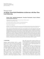
Figure 1: A schematic of Algorithm 1 with greedy pruning for finding the optimal network coding solution of (4). Note that the algorithm
is recursive as it calls Pk−ku −ks −1 and Pk−ku −1 within itself.
Definition 8. A variable xi is said to be unconstrained if Ci =
∅. The set of all unconstrained variables is denoted by U and
is referred to as the unconstrained set.
If xi is an unconstrained variable, then for each row index p,
a pi = 1 ⇒ a p j = 0 for all j = i (otherwise, xi and x j would
/
become constrained).
Example 2. Consider the following receiver-packet incidence
matrix A
⎡
1
⎢1
⎢
⎢0
⎢
⎢
A = ⎢0
⎢
⎢0
⎢
⎣0
0
0
1
0
0
0
0
0
1
0
1
1
0
0
0
0
0
0
1
0
0
0
0
0
0
0
1
0
0
⎤
0
0⎥
⎥
0⎥
⎥
0⎥.
⎥
⎥
0⎥
⎥
1⎦
1
(6)
One can easily verify the relations defined above. For
example, variables x1 and x3 are constrained because for
p = 1, a p1 = a p3 = 1. Variables x1 and x4 are not
constrained to each other because columns a1 and a4 do not
have a nonzero element in the same row position. Variable
x6 is unconstrained because no other column has a nonzero
element in rows 6 or 7. In summary, C1 = {x2 , x3 }, C2 =
{x1 }, C3 = {x1 , x4 }, C4 = {x3 } and C5 = C6 = ∅.
To design an efficient search algorithm, one needs to
efficiently prune the parameter space and reduce the problem
size. We make the following observations for pruning of the
parameter space.
(1) Unconstrained variables must be set to 1. In other
words, setting those variables to 0 does not contribute
to the optimal solution (note that the elements in w
are positive). In the above example, x5 and x6 must
be set to 1 because no other variable is constrained
to them (we will make this statement formal in the
optimality proof of the algorithm in the appendix).
(2) If a constrained variable is set to 1 all members of
its constrained set must be set to 0. In the above
example, setting x1 = 1 forces x2 and x3 to zero.
6
EURASIP Journal on Wireless Communications and Networking
(3) At a given step, the parameter space can be pruned
most by resolving the variable with the largest
constrained set.
Application of the third observation, in a search algorithm
results in greedy pruning of the parameter space. We note
that greedy pruning is only optimal for a given step of the
algorithm and is not guaranteed to result in the optimal
reduction of the overall complexity of the search.
We now make a final remark before presenting the
search algorithm. In particular, we have observed that
finding constrained sets for each variable in each step
of the algorithm can be somewhat time consuming. A
very effective alternative is to first sort matrix A, columnwise, in descending order of the number of 1’s in each
column. Setting the “most important” head variable x1 (with
the highest |M1 |) to 1 is likely to result in the largest
constrained set (because it potentially overlaps with many
other variables) and hence, many variables will be resolved
in the next recursion. We will refer to the approach based
on finding the largest constrained set as the greedy pruning
strategy and to the alterative approach as the sorted pruning
search strategy.
The greedy pruning search strategy is shown in Figure 1,
which with appropriate modifications can also represent the
sorted pruning variation. Let Pk denote the problem of
size k whose input is an N × k receiver-packet incidence
matrix Ak and whose output is a set of solutions of the form
x of length k which satisfy the instantaneous decodability
condition Ak x ≤ 1N . The algorithms can be described as
shown in Algorithm 1.
In the appendix, we prove by structural induction that
Algorithm 1 is guaranteed to return all optimal solutions
of (4). However, we note that not every solution returned
by Algorithm 1 is optimal. The nonoptimal solutions can
be easily discarded by testing against the objective function
(4) at the end of the algorithm. We also note that in
Algorithm 1, we can simply remove those packets received
by every receiver from the problem. If there are K0
such variables, we can start step (1) above from k =
K − K0 instead of K. The Matlab code for both the
greedy and sorted pruning algorithms can be found at
/>We conclude this section by a brief note on the computational complexity of Algorithm 1. Let us denote the number
of recursions required to solve the problem of size k by Ck .
According to Algorithm 1, this problem is always broken into
two smaller problems of size k − ku − ks − 1 and k − ku − 1.
Therefore, one can find the number of recursions required to
solve Pk by recursively computing Ck = Ck−ku −ks −1 + Ck−ku −1 .
The recursion stops when one reaches a problem of size 1
(only one packet to transmit) where C1 = 1.
4. Adaptive Network Coding in the Presence of
Erasure Memory
Here, we present a generalization of the set packing approach
for coded transmission in erasure channels with memory.
The idea is that the importance of a packet m j is no
longer determined by how many receivers need m j , but by
the probability that m j will be successfully decoded by the
receivers that need it. In computing this probability, one can
use the fact that successive channel erasures in a link are
usually correlated with each other and hence, their history
can be used to make predictions about whether a receiver is
going to experience erasure or not in the next time slot. To
present the idea, we focus on the GEC model for representing
channel erasures. More general memory models for erasure
can also be incorporated into our framework.
We define the reward pi of sending a packet to receiver
Ri as the probability of successful reception by Ri in the next
time slot: pi = Pr(Ci, = G | Ci, −1 ), where Ci, −1 is the state
of Ri in the previous transmission round (Statements like
“state of Ri ” should be interpreted as the state of the physical
link Li connecting the source to Ri .). The total reward or
importance of sending packet m j is then
wj =
pi .
(7)
i∈M j
The above weight vector gives higher priority to a packet m j
for which there is a higher chance of successful reception,
because the receivers that need m j are more likely to be in
good state in the next time slot. With this newly defined
weight vector, one can try to solve the optimization problem
given in (4) under the same instantaneous decodability
condition.
Remark 1. We conclude this section by emphasizing that the
optimization framework in (4) is very flexible in accommodating other possibilities for the weight vector w, which
can be appropriately determined based on the application.
For example, instead of allocating the same weight to a
packet needed by a subset of receivers, one can allocate
different weights to the same packet (looking column-wise
at A) depending on the priorities or demands of each user.
In the map update example described in the Introduction,
different emergency units can adaptively flag to the base
station different parts of the map as more or less important
depending on their distance from a certain disaster zone.
The task of the base station is then to send a packet
combination that satisfies the largest total priority. One
can also combine user-dependent packet weights with the
channel state prediction outcomes in a GEC. One possibility
is to multiply the probabilities pi by the receiver priority. It
could then turn out that although a receiver is more likely to
be in erasure in the next transmission round, it may be served
because of a high priority request.
5. Heuristic Search Algorithms
In Section 3.2, we proposed efficient search algorithms for
finding the optimal solution(s) of (4). However, there may
be situations where one would like to obtain a (possibly
suboptimal) solution much more quickly. This may be the
case, for example, when the total number of packets to
be transmitted is very large. Therefore, designing efficient
heuristic algorithms to complement the optimal search is
EURASIP Journal on Wireless Communications and Networking
7
(1) Start with the original problem of size k = K.
(2) if sorted pruning strategy is desired then
(3) Rearrange the variables in Ak in descending order of packet importance (number of 1’s in each column).
(4) end if
(5) Solve (Pk ):
(6) if k = 1 then
(7) Return x1 = 1 (since the variable is not constrained).
(8) else
(9)
if greedy pruning strategy is desired then
(10)
Determine the constrained set for all variables x1 to xk .
(11)
Denote the index of the variable with the largest constrained set by s and the cardinality of its constrained
set by ks .
(12) else
(13)
Determine the constrained set for the head variable x1 with cardinality k1 and also the set of unconstrained
variables (Note that we have overused index 1 to refer to the head variable in the reordered matrix at each
recursion.). Set s = 1.
(14) end if
(15) Denote the cardinality of the unconstrained set U by ku .
(16) Set all the unconstrained variables to 1.
(17) Set xs = 1 and the variables in its corresponding constrained set Cs to 0.
(18) Reduce the problem by removing resolved variables. Reduce Ak accordingly.
(19) Solve (Pk−ku −ks −1 ) (Note that ku unconstrained variables are set to one, xs = 1 and ks variables constrained by xs
are set to zero, hence a total of ks + ku + 1 variables are resolved.).
(20) Combine the solution with previously resolved variables. Save solution.
(21) Set xs = 0.
(22) Reduce the problem by removing resolved variables. Reduce Ak accordingly.
(23) Solve (Pk−ku −1 ) (Note that ku unconstrained variables are set to one and xs = 0, hence a total of ku + 1 variables
are resolved.).
(24) Combine the solution with previously resolved variables. Return solution(s).
(25) end if
Algorithm 1: Recursive search for the optimal solution(s) of (4).
important. In this section, we propose a number of such
heuristics.
5.1. Heuristic 1—Weight Sorted Heuristic Algorithm. The
idea behind this recursive algorithm is very simple. As in
Algorithm 1, we start with the original problem of size
k = K. We then rearrange the columns of the matrix A
in descending order of |w j | (starting from the packet with
the highest weight). Note that this is different from the
sorted pruning version of the Algorithm 1, in which the
columns of A were sorted in descending order of |M j | to
potentially result in large constrained sets. We then set the
head variable x1 = 1 and find its corresponding constrained
set C1 to resolve k1 = |C1 | variables that are to be set
to zero. We then solve the smaller problem of size Pk−k1
and continue until the problem cannot be further reduced.
One main difference between Heuristic 1 and Algorithm 1 is
that at each recursion, the head variable is only set to one;
the other possibility of x1 = 0 is not pursued at all. In a
sense, this heuristic algorithm finds greedy solutions to the
problem at each recursion by serving the highest priority
packet. In this heuristic algorithm, all ku unconstrained
variables are naturally set to 1 in the course of the algorithm.
The computational complexity of this method is at worst
proportional to K, which can happen when there is no
constraint between packets.
5.2. Heuristic 2—Search Algorithm 1 with Maximum Recursions/Elapsed Time. It is possible to terminate the recursive
search Algorithm 1 prematurely once it reaches a maximum
number of allowed recursions/elapsed time. If the algorithm
reaches this value and the search is not complete, it performs
a termination procedure whereby it heuristically resolves the
remaining unresolved packets in the current incomplete
solution. That is, it performs Heuristic 1 on a smaller
problem, which is yet to be solved. It then returns the
best solution that has been found so far. We note that
due the extra termination procedure, the actual number of
recursions/elapsed time can be (slightly) higher than the
preset value.
Two comments are in order here. Firstly, Algorithm 1
is designed to sort the matrix A based on the number of
receivers that need a packet. It only reverts to sorting the
unresolved variables based on the vector w in the termination
process. Secondly, if the maximum number of recursions is
set to one, Algorithm 1 just performs the termination process
and becomes identical to Heuristic 1.
5.3. Heuristic 3—Dynamic Number of Recursions. This
heuristic is based on Heuristic 2, where we dynamically
increase the number of allowed recursions as needed. At
each transmission round, we start with only one allowed
EURASIP Journal on Wireless Communications and Networking
recursion (effectively run Heuristic 1). If the throughput (Let
Q ⊂ {1, . . . , N } denote the index of receivers that still need at
least one packet and RQ denote such receivers. The achieved
throughput at time slot is defined as wT x/ f (RQ ), where x
is the found solution and f (RQ ) is an appropriate function
of receivers’ needs. For memoryless erasures f (RQ ) = |RQ |
and for GEC’s f (RQ ) = q∈Q | pq | (refer to Section 4 and
(7)).) is higher than a desired value, there is no need to
proceed any further. Otherwise, we can gradually increase
the number of recursions by an appropriate step size. This
heuristic stops when it either reaches the maximum allowed
recursions or when increasing the number of recursions does
not result in a noticeable improvement in the throughput.
70
60
50
Median delay
8
40
30
20
10
0
6. Numerical Results and Secondary
Coding Considerations
We start this section by presenting end-to-end decoding delay
results for memoryless erasure channels. We then specialize
to erasure channels with memory. The end-to-end problem
is the complete transmission of K packets. End-to-end
decoding delay of a receiver is the sum of decoding delays for
the receiver in each transmission step. In the following, when
we say “the delay performance of method X”, we are referring
to the delay performance of the end-to-end transmission,
where method X is applied at each step.
In the course of presenting the results and based on
the observed trends, we will discuss some secondary coding
techniques and post processing considerations that can
improve the decoding delay. Throughout the analysis of this
section, we assume independent erasures in different links
with identical probabilities. Hence, we can drop subscript i
when referring to link erasure probabilities.
Figure 2 shows the median of decoding delay for the
transmission of K = 100 packets to N = 3 to N =
100 receivers. Channel erasures are memoryless and occur
with a high probability of p = 0.5 independently in
every link. The median of delay is computed across all
receivers and is, in fact, also the median across many
stochastic runs of the algorithms. The first curve from below
shows the delay obtained from Algorithm 1 (Throughout the
numerical evaluations, we used the sorted pruning version
of Algorithm 1.). The middle curve is the delay obtained by
performing Heuristic 1. The top curve shows a reproduction
of delay results reported in [8] which are based on a random
opportunistic instantaneous network coding strategy. In this
case, the transmitter first selects a packet needed by at least
one receiver at random. Then, it goes over other packets in
some order and adds a packet to the current choice only if
their addition still results in instantaneous decodability. In
comparison, Heuristic 1 performs noticeably better than that
in [8] and more importantly, is not much far away from the
results of Algorithm 1. This is specially important since for
some number of receivers, Heuristic 1 can run considerably
faster than Algorithm 1, which will be shown in the coming
figures shortly.
Figure 3 compares the mean delay performance of
different heuristics presented in Section 5 with that of
0
10
20
30
40
50
60
70
Number of receivers, N
80
90
100
Random opportunistic, Figure 1 in Keller et al. [8]
Heuristic 1
Algorithm 1
Figure 2: Median of decoding delay for the transmission of K =
100 packets to N = 3 to N = 100 receivers. Channel erasures
are memoryless and occur with a high probability of p = 0.5
independently in every link. Algorithm 1, Heuristic 1 and random
Heuristic [8] are compared with each other.
Algorithm 1. Similar to the previous figure, mean delay is
computed across all receivers. The delay performance of
Heuristic 2, Heuristic 3, and Algorithm 1 are close, whereas
Heuristic 1 results in the largest delay. A careful reader may
notice that the end-to-end performance of Heuristic 2 is
at times better than Algorithm 1. While the difference is
practically insignificant, this deserves some explanation. The
end-to-end transmission problem involves making packet
transmission decisions at each step. While all algorithms
start with the same packet incidence matrix (all-ones),
due to packet erasures and as they make decisions about
transmission of packets at each step, they take diverging paths
in the solution space. As a result, they end up with different
packet incidence matrices to solve over time. Hence, it is
conceivable for an algorithm to make suboptimal decisions
at one or more steps and yet end up with a better end-to-end
delay than Algorithm 1 that strictly makes optimal decisions
at every step. Intuition suggests that an algorithm such as
Heuristic 1 that consistently makes suboptimal decisions is
unlikely to outperform Algorithm 1 end-to-end, which is
confirmed by the numerical results. However, an algorithm
such as Heuristic 2 which almost always makes optimal
decisions with only infrequent exceptions, may outperform
Algorithm 1. According to Figure 3, these perturbations in
end-to-end performance are practically insignificant and the
intuitive choice of the optimal or a largely optimal algorithm
at each step will result in the best end-to-end performance.
We note that the delays presented here (and also in the
following figures) are, in fact, excess median or mean delays
beyond the minimum required number of transmissions,
which is K. For example, a mean delay of 10 slots for K =
100 packets signifies on average 10% overhead, which is the
EURASIP Journal on Wireless Communications and Networking
9
70
70
K = 100 packets
Memoryless erasures Pe = 0.5
60
50
Mean delay
Mean delay
50
40
30
20
40
30
20
10
0
K = 100 packets
Memoryless erasures Pe = 0.5
60
10
10% delay− around 15 receivers
→
0
10
20
30
40
50
60
70
Number of receivers, N
Heuristic 1
Heuristic 3
80
90
100
Heuristic 2
Algorithm 1
Figure 3: Mean decoding delay for the transmission of K = 100
packets to N = 3 to N = 100 receivers. Algorithm 1 is compared
with Heuristics 1–3. Both Heuristics 2 and 3 perform very closely
to Algorithm 1. The maximum number of recursions for both
Heuristic 2 and 3 is set to 100.
price for guaranteeing instantaneous decodability. In other
words, one measure of throughput is th1 = K/(K + d),
where d is the mean delay across all receivers. An example
is shown in Figure 3. For up to around 15 receivers in the
system, Algorithm 1, Heuristics 2, and 3 ensure an average
throughput loss of 10%.
It is quite possible that Algorithm 1 returns multiple
network coding solutions all of which have the same
objective value wT x. A natural question that arises is whether
systematic selection of a solution with a particular property
is better than others in the presence of erasures in the
channel. Our experiments verify that indeed some secondary
post processing on the solutions can improve the end-toend delay. In particular, we compare two post processing
techniques: (1) selecting a solution which involves minimum
amount of coding (lowest number of 1’s in the solution
vector x) and (2) selecting a solution with maximum amount
of coding (highest number of 1’s in the solution vector x).
Figure 4 shows the effects of such processing on the overall
decoding delays. It is clear that maximum coding is not a
reasonable choice and results in worse delays compared with
minimum coding. We attempt to explain this behavior by
means of an example and intuitive reasoning. Let us assume
that there are K = 3 packets to be transmitted to N =
3 receivers and at the beginning of the third transmission
round, matrix A is given as follows
⎡
⎤
0 1 1
⎢
⎥
A = ⎣1 0 1⎦.
0 1 1
(8)
It is clear that there are two optimal solutions: we can either
send packets m1 ⊕ m2 or packet m3 by itself, where the former
involves coding and latter is uncoded. Now let us assume that
0
0
10
20
30
40
50
60
70
Number of receivers, N
80
90
100
Heuristic 1
Algorithm 1 using first returned answer
Algorithm 1 using minimum coding
Algorithm 1 using maximum coding
Figure 4: The effect of post processing on mean delay. Whenever
Algorithm 1 returns multiple solutions, minimum amount of
coding should be chosen. Heuristic 1 is shown for reference.
we select the maximum coding strategy and send m1 ⊕ m2 . If
in the third transmission round only R2 successfully receives,
A will become
⎡
⎤
0 1 1
⎢
⎥
A = ⎣0 0 1⎦,
(9)
0 1 1
and clearly the optimal solution is sending packet m3 . If in
the fourth transmission round only R1 successfully receives,
A will become
⎡
⎤
0 1 0
⎢
⎥
A = ⎣0 0 1⎦,
0 1 1
(10)
where it is evident that in the fifth transmission round, we
cannot find a packet which is innovative and instantaneously
decodable for all the three receivers. On the other hand,
one can verify that if we adopt a minimum coding strategy
and send packet m3 in the third transmission round, we
can always find innovative and instantaneously decodable
packets for all three receivers in the future regardless of
erasures in the channel. In summary, solutions with less
coding tend to cause less constrains on the problem in the
future.
It is noted in Figure 4 that the first solution returned
by Algorithm 1 performs almost the same as the minimum
coding solution. The reason for this is that Algorithm 1 first
ranks the packets based on the number of receivers that need
them. Therefore, the first solution picked by the algorithm
is likely to contain packets with largest constrained sets and
hence, many resolved packets are set to zero, which often
translates into small amount of coding. Throughout this
10
EURASIP Journal on Wireless Communications and Networking
×104
×103
10
8
K = 100 packets
Memoryless
erasures Pe = 0.5
100
90
80
70
60
50
40
30
20
10
0
8
7
6
5
4
3
2
1
0
0
10
7
Average number of iterations
Average number of recursions
9
6
5
4
3
2
1
0 10 20 30 40 50 60 70 80 90100
20
Heuristic 1
Heuristic 3
30
40
50
60
70
Number of receivers, N
80
90
100
Heuristic 2
Algorithm 1
0
0
500 1000 1500 2000 2500 3000 3500 4000 4500 5000
Number of packets, K
20 receivers
30 receivers
40 receivers
Figure 5: Average number of recursions in Algorithm 1 and
Heuristics 1–3. The maximum number of recursions for both
Heuristic 2 and 3 is set to 100. By referring to Figure 3, we observe
that for small number of receivers, Heuristics 2-3 can provide same
decoding delays at a fraction of computational complexity.
Figure 6: The effect of increasing the number of packets on the
computational complexity of Algorithm 1 in terms of number of
recursions. The complexity remains linear with the number of
packets for well-sized receiver populations (30 and 40 receivers).
section, unless otherwise stated, we have shown the delay
results based on the first returned solution of Algorithm 1.
It is interesting to analyze the actual number of recursions that the search in Algorithm 1 takes to find the
optimum solution. This is shown in Figure 5 for K = 100
packets along with the number of recursions required in
Heuristics 1, 2, and 3. Algorithm 1 shows three modes of
behavior: low, medium, and high number of recursions.
When the number of receivers is larger than N = 20,
Algorithm 1 finds the optimal solution very quickly and
the number of recursions is very close to the number of
packets K. However, when the number of receivers is lower,
the constraints that each receiver imposes on the network
coding decisions cannot limit the search space enough and
hence, a large number of combinations have to be tested.
Obviously, Heuristic 1 has the lowest number of recursions.
Compared to Heuristic 2 with 100 fixed recursions, dynamic
Heuristic 3 can almost halve the number of recursions
with negligible effect on delay performance (see Figure 3).
By referring to Figure 3, we conclude that for the system
under consideration, the excessive number of recursions in
Algorithm 1 is not warranted as it does not result in any
noticeable delay improvement compared to Heuristics 2 or
3.
Figure 6 shows the effect of increasing the number of
packets on the computational complexity of Algorithm 1 in
terms of number of recursions to complete the search. Three
different numbers of receivers N = 20, N = 30, and N =
40 are considered. The complexity remains linear with the
number of packets for well-sized receiver populations (30
and 40 receivers). This is in agreement with observations
in Figure 5. When the number of receivers is not so large
(see the blue curve in Figure 6 for N = 20), we see a sudden
growth in complexity, in terms of number of recursions,
when K
700 packets. In such situations, truncating the
number of recursion to be linear with the number of packets
(Heuristic 2) is a good alternative.
Figure 7 shows the impact of the number of packets
and also erasure probability on the decoding delay. The
normalized mean delay versus number of packets K is
plotted for three different erasure probabilities Pe = 0.5,
Pe = 0.4, and Pe = 0.2, which are still high erasure
probabilities. The number of receivers is fixed to N = 20.
The delay performance of Heuristics 1 and 3 are shown. A
few observations are made. Firstly, as expected, the delay
(both absolute and normalized measures) decreases as the
erasure probability decreases. Secondly, the difference in the
delay performance between Heuristics 1 and 3 decreases
as the erasure probability decreases. This trend has also
been observed for other number of receivers. Moreover, the
difference between heuristics and Algorithm 1 decreases with
erasure probability, which is not shown here for clarity of
figure. Finally, the normalized delay decreases as the number
of packets increases. We noted, however, that the absolute
delay may increase or decrease depending on the number of
receivers in the system. We attribute possible decrease in the
normalized delay to the fact that when there are more packets
to transmit, the transmitter has more options to choose from
and hence, encounters delays less often in a normalized sense.
An important question that may arise in practical
situations is how to choose the “block size” or the number
of packets that are taken into account for making network
coding decisions. If one has a total of K packets to transmit,
does it make sense to divide them into subblocks of smaller
EURASIP Journal on Wireless Communications and Networking
11
×10−2
100
90
N = 20 receivers
Memoryless erasures
18
80
16
70
14
Mean delay
Normalised delay = mean delay/number
of packets
20
12
10
N = 20 receivers
Memoryless erasures Pe = 0.5
60
50
8
40
6
30
4
20
2
10
100
0
100
150
200
250
300
350
Number of packets, K
Pe = 0.2, heuristic 1
Pe = 0.2, heuristic 3
Pe = 0.4, heuristic 1
400
450
500
Pe = 0.4, heuristic 3
Pe = 0.5, heuristic 1
Pe = 0.5, heuristic 3
Figure 7: The effect of number of packets and erasure probabilities
on the normalized delay. The maximum number of recursions for
Heuristic 3 is set to 100. As the erasure probability decreases, the
delay decreases as expected. The normalized delay decreases with K
for this particular N (this is not always the case).
sizes or does it make sense to treat them as one single block of
packets? The short answer is to include all “order-insensitive”
packets in making transmission decisions and only break
the packets into subblocks when the assumption of order
insensitivity between subblocks breaks down. In the extreme
case, an infinite number of order-insensitive packets provides
an infinite pool of packets to choose from that can satisfy the
demands of all receivers and are instantaneously decodable.
Figure 8 shows the end-to-end delay when the number of
packets in a block is finite and K = 100 packets is chosen as
the reference for comparison. We can see that although the
delay of transmitting λK packets, dλK , can be larger than that
of transmitting K packets dK , the delay does not increase by a
factor of λ. That is dλK < λdK and one does not benefit from
breaking λK packets into λ subblocks of size K packets each.
By treating λ subblocks of size K as one block of size λK, we
add more degrees of freedom in making decisions.
Now we turn our attention to the delay performance of
our algorithms in channels with memory. Figure 9 shows
the mean delay of different algorithms for K = 100 packets
and N = 3 receivers. The GEC parameters for all links are
identical with b = g. The horizontal axis shows the memory
content μ = 1 − 2b. The first curve from above shows
the performance of Algorithm 1 when the transmitter does
not take channel conditions into account in making coding
decisions. In other words, w j = |M j | is used in Algorithm 1
as if the channel states were memoryless. For relatively
large memory contents, this method results in the largest
mean delay. The next curve shows the delay performance
of Heuristic 1. The next two curves, which are almost
150
200
250
300
350
Number of packets, K
400
450
500
Algorithm 1
Heuristic 1
Linear increase in delay
Figure 8: The effect of block size on the mean delay. If the delay of
transmitting K = 100 packets in Heuristic 1, d100 , is taken as the
reference, we can see that the delay of including λ × 100 packets
in transmission is less than λd100 . The same observation applies to
the delay of Algorithm 1. In general, it is recommended to include
all “order-insensitive” packets in making transmission decisions and
only break the packets into subblocks when the assumption of order
insensitivity between subblocks breaks down.
indistinguishable, show the performance of Algorithm 1
which takes channel states into account (using (7)) and
Heuristic 2 with 100 recursions. The last curve shows the
best delay that can be achieved by occasionally violating the
instantaneous decodability rule for one receiver in favor of
the other two receivers that are predicted to be in good state
in the next transmission round. More details can be found in
[14].
Figure 10 shows the delay performance of Algorithm 1
using packet weights according to (7) for N = 3 to N = 15
receivers. Both the mean delay and mean delay plus one
standard deviation of delay (across 1000 stochastic runs of
the transmission) are shown. As expected, the delay increases
as the number of receivers increases. Comparing the delay’s
standard deviation with its mean, we observe that when the
number of receivers is 3–5, the delay is relatively more variant
than when the number of receivers is 10–15. For example,
for N = 3 and μ = 0.984, the ratio of standard deviation to
mean delay is around 3.225/0.8183 4, whereas for N = 15
0.33.
and μ = 0.94 this ratio reduce to only 7.35/22.49
One should keep these variations in mind when designing
the transmission system.
We conclude this section with a brief look at the effect
of post processing on the delay performance in channels
with memory. Figure 11 shows different delays for N = 15
receivers and K = 100 packets. The figure confirms our
earlier finding that selecting the maximum amount of coding
among the optimal solutions provided by Algorithm 1 can
result in larger end-to-end delays. We also note that serving
the maximum number of receivers can have an adverse effect
12
EURASIP Journal on Wireless Communications and Networking
40
2.5
35
K = 100 packets
N = 3 receivers
Identical GEC in each link with b = g
K = 100 packets
N = 15 receivers
Identical GEC in links with b = g
30
Mean delay
Mean delay
2
1.5
1
25
20
15
10
0.5
5
0
0
0.1
0.2
0.3 0.4 0.5 0.6 0.7
Channel memory μ = 1 − 2b
0.8
0.9
1
Figure 9: Delay performance of different algorithms in GilbertElliott channels. The maximum number of recursions for Heuristic
2 is set to 100. By predicting next channel states and defining packet
weights accordingly (see (7)), one can achieve considerably lower
delays.
0.1
0.2
0.3 0.4 0.5 0.6 0.7
Channel memory μ = 1 − 2b
0.8
0.9
1
Figure 11: The effect of post processing on mean delay. As
explained in the main text, whenever Algorithm 1 returns multiple
solutions, choosing the maximum amount of coding and serving
maximum number of receivers can often have adverse effects on the
delay.
on the delay in GEC’s. To explain this, consider an example
where there are K = 2 left packets to be transmitted to
N = 100 receivers. Packet 1 is needed by R1 to R99 and packet
2 is needed by R99 and R100 . Since both packets are needed
by R99 , we can either send packet 1 or 2, but not both. Now
assume that R1 to R99 are all predicted to be in good state with
probability 0.01 and R100 is predicted to be in good state with
probability 0.98, so that w1 = w2 = 0.99 according to (7).
Therefore, transmission of either packet seems to be equally
optimal. However, one can easily verify that the probability
of at least one receiver among R1 to R99 receiving packet 1
is only 1 − 0.9999 = 0.63, whereas the probability of either
R99 or R100 receiving packet 2 is 1 − 0.99 ∗ 0.02 = 0.9802.
Therefore, it makes sense to satisfy only two receivers, one of
which has a high priority due its good channel conditions.
30
Mean and standard deviation of the delay
0
Algorithm 1, but blind to channel states (w j = |M j |)
Heuristic 1
Algorithm 1 with weights from (7) using max
coding for max receivers
Algorithm 1 with weights from (7) using
first returned answer
Algorithm 1, but blind to channel states (w j = |M j |)
Heuristic 1
Heuristic 2
Algorithm 1 with predictive weights using (7)
Special case for N = 3 receivers [14]
25
20
15
10
5
0
0
0
0.1
0.2
0.3 0.4 0.5 0.6 0.7
Channel memory μ = 1 − 2b
3 receivers mean + std dev
5 receivers mean + std dev
10 receivers mean + std dev
15 receivers mean + std dev
0.8
0.9
1
3 receivers mean
5 receivers mean
10 receivers mean
15 receivers mean
Figure 10: Delay performance of Algorithm 1 with weights defined
using (7) for different number of receivers. As expected, the delay
increases with the number of receivers. Both the mean delay
(solid curves) and mean delay plus one standard deviation of
delay (dashed-dotted curves) across 1000 stochastic runs of the
transmission are shown.
7. Conclusions
In this paper, we provided an online optimal network coding
scheme with feedback to minimize decoding delay in each
transmission round in erasure broadcast channels. Efficient
search algorithms for the optimal network coding solution,
as well as heuristic methods were presented and their
delay and computational performance were tested in several
system scenarios. We found that adopting an optimized
approach using as much information about the channel
as possible, such as memory, leads to a significantly better
decoding delay. An interesting problem for future research is
EURASIP Journal on Wireless Communications and Networking
13
to relax the instantaneous decodability condition to L-step
decodability and investigate the delay-throughput tradeoff.
(ii) Since xk−ku +1 to xk are unconstrained, no column
ak−ku +1 to ak can have ones in the same row position.
Hence, 1ak−ku +1 + · · · + 1ak ≤ 1N .
Appendix
(iii) Using similar arguments, we can assert that no
column in A or a1 can have ones in the same row
positions as ak−ku +1 to ak do. Therefore, 1a1 + A x1 +
1ak−ku +1 + · · · + 1ak ≤ 1N and x is a solution.
Here we prove by structural induction that (a) every result
returned by Algorithm 1 is a solution of (4) and (b) the
set of solutions returned by the algorithm contains all the
optimal solutions. We note that the algorithm is designed to
discard infeasible vectors and those solutions that are clearly
suboptimal at each recursion to improve performance. The
latter is based on positiveness of the elements of w as
explained below.
The algorithm generates a binary tree. Each node represents a problem of size k and Pk , and branches into two
subproblems of size Pk−ku −ks −1 and Pk−ku −1 . The former
subproblem is a result of setting xs = 1 and the latter a result
of setting xs = 0. A leaf is reached when we need to solve P1 .
Without loss of generality let us assume that the variable to be
examined is the first variable (s = 1) which is followed by ks
variables (x2 to xks +1 ) that are constrained to x1 , k − ku − ks − 1
variables (xks +2 to xk−ku ) that are constrained but not to x1 ,
and finally ku unconstrained variables xk−ku +1 to xk . This can
be easily accomplished by rearranging the columns of A.
For k = 1, it is clear that the only optimal solution
to P1 is x1 = 1 which is returned by the algorithm.
Hence, the minimal structure of the algorithm returns the
optimal solution and our claim is true for k = 1. The
induction hypothesis is that the two subproblems Pk−ku −ks −1
and Pk−ku −1 have only discarded infeasible vectors and
some suboptimal solutions. We need to prove that the same
statement applies to the parent problem Pk .
We first look at the left branch where x1 = 1. According
to the construction of the algorithm, any solution such as x1
of length k − ks − ku − 1 provided by the left branch Pk−ks −ku −1
is appended by the parent problem Pk to form
is the only solution that is not trivially suboptimal.
Now we look at the right branch where x1 = 0. According
to the construction of the algorithm, a given solution such as
x0 of length k − ku − 1 provided by the right branch Pk−ku −1
is appended by the parent problem Pk to form
x = 1, 0, 0, . . . , 0, x1 , 1, 1, . . . , 1 ,
x = 0, x0 , 1, 1, . . . , 1 ,
ks
(A.1)
where the head variable x1 is set to one, variables constrained
to x1 are set to zero and all unconstrained variables are set to
one. We first prove that x is indeed a solution and then show
that changing any element of x results in either an infeasible
or a clearly suboptimal x. We use Definitions 6–8.
(i) For
ks
(v) Since we have already found a solution x where the
first and last ku variables are one, we know that any
other solution such as x with one or more zeros
in these positions becomes suboptimal and can be
discarded. That is, wT x < wT x due to positiveness
of elements of w.
(vi) Finally, according to induction hypothesis, we know
that x1 cannot be changed into anything other than
what Pk−ks −ku −1 provides without making it either
infeasible or suboptimal.
In summary, for each solution x1 provided by the left
branch Pk−ks −ku −1 , the constructed vector
x = 1, 0, 0, . . . , 0, x1 , 1, 1, . . . , 1 ,
ks
(A.3)
ku
(A.4)
ku
ku
x = 1, 0, 0, . . . , 0, x1 , 1, 1, . . . , 1 ,
(iv) We now argue that variables x2 to xks +1 cannot be
anything other than zero. This directly follows from
the fact that x1 is constrained with xi for 2 ≤ i ≤
ks + 1 and hence, in any given solution they cannot be
simultaneously one.
(A.2)
ku
we write the condition Ax as a weighted sum of
columns of A. That is, Ax = 1a1 + A x1 + 1ak−ku +1 +
· · · + 1ak , where A is a submatrix of A of size
N × (k − ks − ku − 1), which is input to Pk−ks −ku −1 , and
according to the induction hypothesis A x1 ≤ 1N . But
since no variable in Pk−ku −ks −1 is constrained to x1 , no
column in A and a1 can have ones in the same row
position. Therefore, 1a1 + A x1 ≤ 1N .
where the head variable is set to zero and all unconstrained
variables are set to one. We need to show that for a given
x0 this is indeed a solution. We then show that changing
any element of x can only result in an infeasible vector, a
clearly suboptimal solution, or a duplicate solution already
provided by the left branch and hence, can be discarded. We
use Definitions 6–8.
(i) We write Ax as Ax = 0a1 + A x0 + 1aks +2 + · · · + 1ak ,
where A is a submatrix of A of size N × (k − ku −
1), which is input to Pk−ku −1 , and according to the
induction hypothesis A x0 ≤ 1N . Similar to the
arguments for the left branch, we can assert that no
column ak−ku +1 to ak corresponding to unconstrained
variables can have ones in the same row position.
Hence, 1ak−ku +1 + · · · + 1ak ≤ 1N . Furthermore, that
no column in A can have ones in the same row
positions as ak−ku +1 to ak . Therefore, A x0 +1ak−ku +1 +
· · · + 1ak ≤ 1N and x is a solution.
14
EURASIP Journal on Wireless Communications and Networking
(ii) Since we have already found a solution x where the
last ku variables are one, we know that any other
solution such as x with one or more zeros in these
positions becomes suboptimal and can be discarded.
(iii) Finally, we show that any vector of the form
x = 1, x0 , 1, 1, . . . , 1
(A.5)
ku
with a one in the first variable is either infeasible
or is already constructed based on solutions from
the left branch and hence, need not be considered twice. We consider two possibilities for x0 =
[x2 , . . . , xks +1 , xks +2 , . . . , xk−ku ]. If xi = 1 for any 2 ≤
i ≤ ks + 1, then we have already shown in the analysis
of the left branch that
x = 1, x0 , 1, 1, . . . , 1
(A.6)
ku
is infeasible because x1 and xi are constrained to each
other. If none of x2 to xks +1 are one, then x will be of
the form
x = 1, 0, 0, . . . , 0, x1 , 1, 1, . . . , 1
x0
(A.7)
ku
for some x1 . But, x1 has to be a solution of Pk−ks −ku −1 .
Hence, considering vectors of the form
x = 1, 0, 0, . . . , 0, x1 , 1, 1, . . . , 1
x0
(A.8)
ku
does not lead to any new solution.
In summary, for each solution x0 provided by the right
branch Pk−ku −1 , the constructed vector
x = 0, x0 , 1, 1, . . . , 1
(A.9)
ku
is the only novel solution that is not trivially suboptimal.
By combining the arguments of left and right branch, the
induction claim is proven.
Acknowledgments
The authors wish to thank anonymous reviewers for their
valuable comments which helped to improve the presentation of this paper. In the early stages of this work,
the authors benefited from fruitful discussions with Ralf
Koetter. This paper is dedicated to his memory. Preliminary
results of this paper were presented in the 2009 Workshop
on Network Coding, Theory and Applications (NetCod
2009), Lausanne, Switzerland. The work of P. Sadeghi was
supported under ARC Discovery Projects funding scheme
(Project no. DP0984950). The work of D. Traskov was
supported by the European Commission in the framework of
the FP7 Network of Excellence in Wireless COMmunications
NEWCOM++ (Contract no. 216715).
References
[1] A. Shokrollahi, “Raptor codes,” IEEE Transactions on Information Theory, vol. 52, no. 6, pp. 2551–2567, 2006.
[2] T. Ho, M. Medard, R. Koetter, et al., “A random linear
network coding approach to multicast,” IEEE Transactions on
Information Theory, vol. 52, no. 10, pp. 4413–4430, 2006.
[3] A. Eryilmaz, A. Ozdaglar, and M. Medard, “On delay performance gains from network coding,” in Proceedings of the IEEE
Annual Conference on Information Sciences and Systems (CISS
’06), pp. 864–870, Princeton, NJ, USA, March 2006.
[4] D. E. Lucani, M. Stojanovic, and M. Medard, “Random
linear network coding for time division duplexing: when to
stop talking and start listening,” in Proceedings of the IEEE
Conference on Computer Communications (INFOCOM ’09),
pp. 1800–1808, April 2009.
[5] J.-K. Sundararajan, D. Shah, and M. Medard, “Feedback-based
online network coding,” Submitted to IEEE Transactions on
Information Theory, />[6] J.-K. Sundararajan, P. Sadeghi, and M. Medard, “A feedbackbased adaptive broadcast coding scheme for reducing in-order
delivery delay,” in Proceedings of the Workshop on Network
Coding, Theory, and Applications (NetCod ’09), Lausanne,
Switzerland, June 2009.
[7] V. K. Goyal, “Multiple description coding: compression meets
the network,” IEEE Signal Processing Magazine, vol. 18, no. 5,
pp. 74–93, 2001.
[8] L. Keller, E. Drinea, and C. Fragouli, “Online broadcasting
with network coding,” in Proceedings of the 4th Workshop on
Network Coding, Theory, and Applications (NetCod ’08), Hong
kong, January 2008.
[9] D. Bertsimas and R. Weissmantel, Optimization Over Integers,
Dynamic Ideas, Belmont, Mass, USA, 2005.
[10] T. S. Rappaport, Wireless Communications, Principles and
Practice, Prentice Hall, Upper Saddle River, NJ, USA, 2nd
edition, 2002.
[11] P. Sadeghi, R. A. Kennedy, P. B. Rapajic, and R. Shams,
“Finite-state Markov modeling of fading channels: a survey of
principles and applications,” IEEE Signal Processing Magazine,
vol. 25, no. 5, pp. 57–80, 2008.
[12] M. Mushkin and I. Bar-David, “Capacity and coding for
the Gilbert-Elliot channels,” IEEE Transactions on Information
Theory, vol. 35, no. 6, pp. 1277–1290, 1989.
[13] S. Katti, H. Rahul, W. Hu, D. Katabi, M. Medard, and
J. Crowcroft, “XORs in the air: practical wireless network
coding,” in Proceedings of the ACM Computer Communication
Review (SIGCOMM ’06), vol. 36, pp. 243–254, ACM Press,
October 2006.
[14] P. Sadeghi, D. Traskov, and R. Koetter, “Adaptive network
coding for broadcast channels,” in Proceedings of the Workshop
on Network Coding, Theory, and Applications (NetCod ’09), pp.
80–85, Lausanne, Switzerland, June 2009.