Development and Implementation of RFID Technology Part 10 ppt
Bạn đang xem bản rút gọn của tài liệu. Xem và tải ngay bản đầy đủ của tài liệu tại đây (3.96 MB, 30 trang )
14
The Study of RFID Authentication Protocols and
Security of Some Popular RFID Tags
Hung-Yu Chien
Department of Information Management, National Chi Nan University,
Taiwan, R.O.C.
1. Introduction
A radio frequency identification (RFID) system consists of three components: radio
frequency (RF) tags (or transponders), RF readers (or transceivers), and a backend server.
Tag readers inquire tags of their contents by broadcasting an RF signal, without physical
contact, at a rate of several hundred tags per second and from a range of several meters. The
advancements of Silicon manufacturing also result in great cost reduction for RFID tags
compared to barcodes, not to mention that the tags can carry more data and are more
resistant to dust and twisting. Thanks to these excellent features, the world has seen many
RFID systems already put to use by manufacturers and businesses of all kinds of goods for
supply management and inventory control and such; in addition, many public facilities and
parking lots have also brought in RFID systems to help them offer faster, easier and more
user-friendly services. As a matter of fact, potential applications are everywhere [57]. Such
features as great convenience, low cost, and wide applicability will soon make RFID systems
the most pervasive microchips in history [57].
However, the wide distribution of RFID systems into modern society may very much likely
get the security of both businesses and consumers exposed to threats and risks. For example,
businesses may have malicious competitors on the market that collect unprotected RFIDs to
gather information illegally, spread false tags to provide wrong information, or even launch
denial of service (DOS) attacks against them. On the other hand, as a consumer, it is
naturally preferred that the information of the purchase of RFID-tagged products be kept
private from outsiders; however, a tag reader at a fixed location can read the content of an
un-protected tag, tracing the RFID-tagged product or/and even identifying the person
carrying the tagged product. Correlating data collected from multiple tag readers such as
their locations and so on can also possibly be used to spy on an individual and track down
his/her social interactions. Besides passive eavesdropping and tracking, a thief might use
counterfeit tags to fool automated checkout or security systems into accepting wrong
information like price, proof of presence or other information.
RFID authentication protocols
To protect the private information on the RFID tags, some special devices (such as a blocker
tag [26]) can be used here to deter the reader from accessing the tags, or tag authenticates
the reader before its access. An RFID authentication protocol is a cryptographic protocol that
Development and Implementation of RFID Technology
262
allows a reader and a tag to authenticate each other, and the protocol is especially suitable
for cases where resource-limited RFID tags are involved. In fact, although there are high-
cost RFID tags like [25] available on the market that can support conventional symmetric
key computations or even public key computations, the mainstream tags targeted at the
majority of consumers are low-cost and can only support simple computations and very
limited storage [50]. For example, for such tags as Gen 2 [16, 58] or iso 15693, conventional
authentication protocols that require symmetric key computations or even public key
computations are not applicable. Therefore, most of the efforts both the businesses
concerned and the academic community have made so far are focused on the research and
development of low-cost tags with higher security levels. Therefore, the topic of the next
section is authentication protocols that are designed for low-cost RFIDs. Please also note that
since well-designed conventional cryptographic protocols can be effectively implemented
on resource-abundant backend servers and readers, it is usually assumed that the channels
between backend servers and readers are secure; however, now that the focus is on RFID
authentication protocols, this study has to assume that the channel between tags and readers
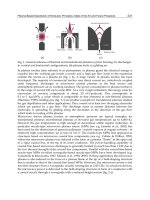
is insecure. Figure 1 shows the components of an RFID system.
Fig. 1. Components of RFID systems
In addition, there are two special situations where the authentication of RFID tags is
required to be done on extra conditions. To begin with, yoking proof protocols like [4, 7, 23,
24, 48, 53, 60] require the proof of simultaneous presence of two (or more) tags, and RFID
distance bounding protocols like [5, 39, 56], on the other hand, not only authenticate the tags
but also ensure that the authenticated tags are within a pre-assumed distance from the
verifiers (the readers) so that the system is immune to message relay attacks like those
brought up by [56]. In the following paragraphs, we shall briefly introduce yoking proof
protocols and RFID distance bounding protocols. For detailed information, please refer to [4,
5, 7, 23, 24, 39, 48, 53, 56, 60].
Yoking proof
In 2004, Juels introduced an interesting RFID yoking proof protocol [23], which allows a
verifier to prove the simultaneous presence of two tags in the communication range of a
specific reader. Juels proposed several possible yoking proof protocol applications [23]. Let
us take one example. Suppose a hard disk manufacturer wishes to ship each hard disk with
its information leaflet. In such a case, each hard disk and each leaflet can be labeled with a
different tag so that the yoking protocol can be applied to prove the simultaneous presence
of the tagged products before shipping. In fact, the yoking proof protocol is a variant of the
cryptographic authentication protocol, and it additionally requires the evidence of the
simultaneous presence of two tags (or more tags).
Tag
Reader
Eavesdropper
Server
Secure channel
Insecure channel
The Study of RFID Authentication Protocols and Security of Some Popular RFID Tags
263
RFID distance bounding protocols
Due to the short communication range, an authenticated RFID tag is deemed to be in
proximity by its verifier (for example, an RFID reader), and the security of many RFID
applications depends on this proximity assumption. However, this belief of proximity could
be maliciously manipulated and thus become misleading when relay attacks like [56] are
launched. For example, the access control system of a building would allow the access only
when an authenticated tag is in the proximity. However, a specific kind of relay attack
named the mafia attack, introduced by Desmedt [14], could cheat the system where an
attacker sets up a rogue tag (say
ˆ
A
) and a rogue reader (say
ˆ
B
) sitting between the real
reader and the real tag, and
ˆ
A
and
ˆ
B
cooperatively relay the messages between the real tag
and the real reader so that the real reader wrongly believes that the tag is in its proximity
(but it is not). A distance bounding protocol is a cryptographic mechanism that can prevent
relay attacks from working. It is executed by a tag A and a reader B, and the tag A can
convince the reader B of A’s identity and A’s physical proximity to B.
2. RFID authentication protocols
An RFID authentication protocol provides mutual authentication between the reader and
the tag, and should resist potential security threats and attacks like the replay attack, man-
in-the middle attack, etc. In addition to mutual authentication, anonymity and forward
secrecy are also desirable properties for RFIDs. The point of ensuring the system’s
anonymity is to protect the privacy of the tags’ identities such that un-authorized readers
cannot identify or track a specific tag. Forward secrecy property, on the other hand, aims to
protect the past communications where a tag is involved even if we assume that an attacker
may have the power to compromise the tag some time later [50].
Just like tags of variant kinds currently available on the market, RFID authentication
protocols can be quite different from one another, and the differences may come from the
distinct resources required or the varied mechanisms adopted. Accordingly, we can classify
these protocols and specify the features each kind has. Following the classification brought
up by [52], for example, a protocol can be either a single-round design or a multi-round
system. The former allows the reader and the tag to authenticate each other after a single
round of operation of the protocol, while the latter has to run multiple rounds to do the job.
Generally speaking, a single round protocol is more efficient than a multi-round protocol in
terms of the number of interactions. Another classification, proposed by Chien [11], is based
on the resources demanded by the protocols. This classification is very practical, because as
we said earlier, on the market there are varieties of tags, of which most are resource-limited,
and the resources required by these protocols can be very different. Under such
circumstances, of course we will have a better view of the whole market if we classify the
protocols and tags according to what kinds of resources are required. A third classification
is based on the kind of cryptographic approach adopted, for the approach decides how well
the protocol performs. Section 2.1 classifies the protocols as either single-round methods or
multi-round methods, reviews the protocols and discusses the security properties. In Section
2.2, according to the required resources, we classify the protocols into four classes and
introduce their corresponding applications. Finally, based on the cryptographic approaches,
Section 2.3 classifies the protocols and discusses their performance.
Development and Implementation of RFID Technology
264
2.1 RFID authentication protocols
Some single-round protocols are introduced in Section 2.1.1~2.1.6, while multi-round
protocols are introduced in Section 2.1.7. Even though tags’ data and keys are stored in the
backend server in most of the cases, we do not differentiate the role of backend sever and
the reader to simplify the description in the following sections. The notations used are
introduced as follows.
,,
TR
rr r : l-bit random numbers.
,
TR
ID ID : the identity of tag T, the identity of reader R.
i
k : the secret key shared between tag
i
T and the reader R.
()h , ()
g
: secure one-way hash function; ()h , ()
g
:
{0,1}* {0,1}
l
→
.
()CRC
: cyclic redundancy code.
()
f
: a pseudo random number generator (PRNG function).
2.1.1 Weis et al.’s schemes
Weis et al. proposed a series of RFID authentication protocols [63, 64], and we review their
hash-based access control protocol and the randomized access control.
Hash-based access control: Each hash-enabled tag
i
T
in this design will have a portion of
memory reserved for a temporary
i
metaID
and will operate in either a locked state or an
unlocked state. Initially, a tag owner stores the hash of a random key,
()
ii
metaID h k←
, in the
tag through either the RF channel or a physical contact to lock the tag. The owner also stores
both the key and the
i
metaID
in a backend server. Upon receipt of a
i
metaID
value, the tag
enters its locked state, and responds to all queries with only its
i
metaID
and offers no other
functionality. To unlock a tag, the owner inquires the tag, looks up the appropriate key in
the back-end database and finally transmits the key to the tag. The tag hashes the received
key and compares it to the stored
i
metaID
. If the values match, the tag unlocks itself and
offers its full functionality to any nearby readers. The protocol is depicted in Figure 2.
Fig. 2. Weis et al.’s Hash-based scheme: unlocking protocol
Randomized access control: In the previous scheme, a tag always responds with its
i
metaID
to the queries, which allows any party to track an individual. So, Weis et al. proposed their
randomized access control schemes where a tag will not respond predictably to queries by
unauthorized users, but must still identifiable by only legitimate readers. The randomized
access control schemes require tags equipped with a random number generator, in addition
to the one-way hash function. Upon receiving a query from the reader, a tag responds with
the values
(, ( || ))
i
rhID r , where r is a randomly chosen number. A legitimate reader
identifies one of its tags by performing a brute-force search of its known IDs, hashing each
of them concatenated with r until it finds a match. This mode is only feasible for owners of a
relatively small number of tags. The protocol is depicted in Fig. 3.
The Study of RFID Authentication Protocols and Security of Some Popular RFID Tags
265
Fig. 3. Weis et al.’s randomized access control
Weakness of the hash-based scheme: In Figure 2, the reader broadcasts the tag’s key in the
forward channel. Since the signal in forward channel is strong enough for an adversary to
monitor the transmission without being detected, this will allow an adversary easily
eavesdrop the key and spoof a legal reader later.
Weaknesses of the random-access scheme: The Random-access scheme was designed to
protect the metaID in the hash-based scheme to avoid individual tracking. However, it has
poor scalability: it cannot support a large volume of tags because it has to perform the brute-
force search to find a matched ID. It also gives the adversary (who resides in the range of the
backward channel) a very high probability to find the matched tag, since he also searches
only a small database of possible IDs. What makes it worse: the legal reader will broadcast
the matched ID in the forward channel. So, an adversary might record the eavesdropped
data (
,( ||)
k
rhID r ) and then easily spoofs the tags later.
2.1.2 Ohkubo et al.’s scheme [43]
The reader and each tag
x
T
initially shares a distinct hash seed
1_ x
s
.
x
T
updates
1_ _
()
ix ix
s
hs
+
=
for 1i ≥ and responds with
__
()
ix ix
ags
=
in the i-th authentication, where h()/g() are two
different hash functions. The reader can follow the hashing chains to authenticate the tag.
The protocol is depicted in Fig. 4.
This scheme provides only one-way authentication of the tag, but it owns the forward
secrecy property; that is, even assuming a tag is compromised some day in the future, the
past communications from the same tag can not be traced. However, Ohkubo et al.’s original
version cannot resist the replay attack [1]- a simple replay of old message can cheat the
reader into accepting a forged tag. The scheme has the poor scalability problem [2, 3] – the
computational cost to identify a tag is O(nm), where n is the number of potential tags and m
is the maximum length of the hash chain. Avoine et al. [1] discussed the techniques to
conquer the replay attack, and Avoine et al. [1, 2] also proposed their improvements to
reduce the time complexity at the cost of extra memory.
Fig. 4. Ohkubo et al.’s scheme
R T
x
Request
a
i_x
s
i_
s
i+1_
h h h
a
i_x
a
i+1
g g
Development and Implementation of RFID Technology
266
2.1.3 Karthikeyan-Nesterenko’s scheme [28]
Karthikeyanand and Nesterenko, based on simple XOR operation,
⊕
, and matrix operation,
designed an efficient tag identification and reader authentication scheme. Initially, two
matrices
1
M
and
1
2
M
−
are stored on each tag, and two matrices
2
M
and
1
1
M
−
are stored on
the reader, where all the matrices are of size
p
p
×
, and
1
1
M
−
and
1
2
M
−
are the inverses of
1
M
and
2
M
respectively. The tag and the reader also store a key K which is a vector of size
q, where q=rp. That is, K can be represented as K=[K
1
, K
2
, …, K
r
], where
, 1,2 ,
i
K
ir=
are
vectors of size
p
. As a slight abuse of notation, the notation X=KM, where K is a vector of
size q and M is a
p
p
×
matrix, denotes a component-wise multiplication of K and M. That
is, X=[X
1
, …,X
r
]=[K
1
M,…,K
r
M].
When the reader inquires a tag, the tag computes
1
XKM=
, and sends back
X
to the
reader. The reader then forwards the message to the backend server, where the server will
search its database to find a match. If it can find a match, then the tag is identified, and the
server performs the following operations to authenticate itself to the tag and renew the key.
The server first computes
12 2
( )
r
YKK KM=⊕⊕⊕
, randomly selects a vector
new
X
of size
q, computes
1
1new new
K
XM
−
= and
2new
Z
KM=
, and finally sends (
Y
,
Z
) to the reader, which
forwards (Y ,
Z
) to the tag. Upon receiving the response from the reader, the tag verifies
whether the equation
?
1
212
( )
r
YM K K K
−
=⊕⊕⊕ holds; if so, the tag updates the key as
1
2new
K
ZM
−
= . The scheme is depicted in Fig. 5.
Fig. 5. Karthikeyan-Nesterenko’s scheme
Weaknesses of Karthikeyan-Nesterenko’s scheme
The scheme cannot resist the following attacks and threats- Denial of Services attack (DOS),
replay attack and individual tracing.
In Karthikeyan-Nesterenko’s scheme, the tag does not authenticate the received value Z
when updating the key. Therefore, an attacker can replace the transmitted Z with an old one
Z
or any random value Z* without being noticed; Upon receiving a valid Y and the fake Z*,
the tag will authenticate the Y successfully and then will update the key as
*1*
2
K
MZ
−
=⋅. So,
the legitimate reader and the tag cannot authenticate each other any more since the key is
wrongly updated.
If the attacker replaces the Z with an old one
Z
(assuming Y and
Z
are previously sent in
the ith legal session) in the above mentioned attack, then the attacker can replay the
Y in
The Study of RFID Authentication Protocols and Security of Some Popular RFID Tags
267
the next session to cheat the tag in wrongly accepting the request and access the tag
accordingly. He can even record the transmitted data from several sessions, and then
launches the above attack several times. This will allow the attacker to trace the tag.
Therefore, the anonymity property is violated.
2.1.4 Duc et al.’s scheme [15]
Duc et al.’s scheme was designed for improving the security of EPCglobal Class-1
Generation-2 tag (which is called Gen-2 for short later). Initially, each tag and the backend
server share the tag’s EPC code (the identity of the tag), the tag’s access PIN, and an initial
key K
0
(this key will be updated after each successful authentication, and
i
K
denotes the key
after ith authentication). The steps of (i+1)th authentication are described as follows, where
“Reader Æ tag: M” denotes the reader sends the tag a message M.
1. Reader Æ tag: Query request.
2. Tag Æ reader Æ server:
1
M
, r , C .
The tag selects a random number
r , computes
1
(||)
i
M
CRC EPC r K
=
⊕ and
1
()CCRCM r=⊕, and sends back (
1
M
, r , C ) to the reader, where the reader will forward
(
1
M
, r , C ) to the backend server.
3. Server Æ reader: the tag’s info or “failure”.
For each tuple
(,)
i
EPC K in its database, the server verifies whether the equations
?
1
(||)
i
M
KCRCEPCr⊕= and
?
1
()CCRCM r=⊕ hold. If it can find a match, then the tag is
successfully identified and authenticated, and the server will forward the tag’s information
to the reader and proceed to the next step; otherwise, it stops the process with failure.
4. Server Æ Reader Æ tag: M
2
To authenticate itself to the tag and update the information on the tag, the server computes
2
(||||)
i
M
CRC EPC PIN r K=⊕ and sends M
2
to the tag through the reader. Upon receiving
M
2
, the tag uses its local values to verify the received M
2
. If the verification succeeds, the tag
will accept the “end session” command in the next step.
5. Reader Æ tag: “end session”
Reader Æ server: “end session”.
• Upon receiving the “end session” command, both the server and the tag update their
shared key as
1
()
ii
K
fK
+
=
.
The weaknesses
Duc et al.’s scheme cannot resist the DOS attack against tags and readers, cannot detect the
disguise of tags, and cannot provide forward secrecy.
(1) In the last step of Duc et al.’s scheme, the reader sends the “end session” commands to
both the tag and the backend server to update the key. If one of the “end session”
commands is intercepted, then the shared key between the tag and the server will be out of
synchronization. Thus, the tag and the reader cannot authenticate each other any more. The
DOS attack succeeds. (2) If it is the “end session” command to the server is intercepted, then
the server will hold the old key; therefore, a counterfeit tag can replay the old data (M
1
, r, C)
to disguise as a legitimate tag. So, the scheme fails to detect a disguised tag. (3) The scheme
cannot provide forward secrecy. Suppose a tag is compromised, then the attacker would get
the values ( EPC , PIN ,
i
K
) of the tag;So, from the eavesdropped data (M
1
, M
2
, r) of the
Development and Implementation of RFID Technology
268
Fig. 6. Due et al. scheme
past communications, the attacker can verify whether a communication comes from the
same tag by performing the following checking. For each eavesdropped communication
(M
1
, M
2
, r), he computes
12
M
M⊕
to derive the value ()CRC EPC r⊕⊕
(||||)CRC EPC PIN r , and then, using the compromised values ( EPC , PIN ,
i
K
) and the
eavesdropped r, he can do the same computation to verify whether it came from the same
tag. So, the past communications of a compromised tag can be traced.
2.1.5 Peris-Lopez et al.’s protocols [45-47]
Peris-Lopez et al. proposed a series of ultra-lightweight RFID authentication protocols [45-
47] which were designed for very low-cost tags. Their schemes were very efficient: they
require about 300 gates only and involve only simple bitwise operations. We review the
LAMP protocol [45], which is one of Peris-Lopez et al.’s ultra-lightweight protocols.
LMAP involves only simple bitwise operations- bitwise XOR (
⊕
), bitwise AND ( ∧ ),
bitwise OR (
∨ ), and addition mod 2
m
(+). The random number generator is only required
on the reader. To protect the anonymity of tags, they adopt the technique of pseudonyms
(IDSs), which is 96-bit length and is updated per successful authentication. Each tag shares
an IDS and four keys (called K1
,
K2, K3, and K4, each with 96 bits) with readers, and they
update the IDS and the keys after successful authentication. It needs 480 bits of rewritable
memory and 96 bits for static identification number (ID).
The protocols consist of three stages- tag identification phase, mutual authentication phase,
and pseudonym updating and key updating phase. In the following,
i
ID denotes the static
identification of Tag
i
,
n
i
IDS denotes the pseudonym of Tag
i
at the n-th run, and
1/ 2/ 3/ 4
nnnn
iiii
K
KKK denote the four keys of Tag
i
at the n-th run. LMAP is depicted in Fig. 7.
Tag identification: Initially, the reader sends “hello” to probe Tag
i
, which responds with its
current
n
i
IDS .
Mutual authentication phase: the reader uses
n
i
IDS to find the corresponding four keys in
its database, via the help of the backend server. It then randomly selects two integers n1 and
The Study of RFID Authentication Protocols and Security of Some Popular RFID Tags
269
n2, and computes the values A, B, and C (the calculation equations are specified in Fig. 7).
From A||B||C, Tag
i
first extracts n1 from A, and then verifies the value of B. If the
verification succeeds, then it extracts n2 from C, and computes the response value D. Upon
receiving D, the reader verify the data D to authenticate the tag.
Pseudonym updating and key updating: After the reader and the tag authenticated each
other, they update their local pseudonym and keys as specified in Fig. 7.
Fig. 7. LMAP
The weaknesses
The authentication of reader and tag in LMAP depends on the synchronization of
pseudonym and keys. However, it is very easy to de-synchronize these values by
intercepting the data in Step 4. In addition to the DOS attack, one can fully disclose the
secrets of tags as follows.
We assume that an attacker can intercept, modify, and replay message between reader and
tag in a reasonable time, and there is a completion message to indicate the completion of
successful authentication. The attack scenario consists of five phases, but our attack is much
more efficient than Li-Wang’s work [34]. The whole scenario is depicted in Fig. 8.
In the attack scenario in Fig. 8, we omit the superscript n and the subscript i of pseudonym
and of keys without causing ambiguity, since we are attacking the same tag within a
successful session. In Phase 1, an attacker impersonates a reader and acquires the current
IDS of a tag, and then the attacker (now impersonating the tag) uses the IDS to get a valid
message A||B||C from the reader in Phase 2.
In Phase 3, the attacker iteratively inverts the j-th (for
196j
≤
≤
) bit of A, modifies B, and
sends
''
|| ||
jj
A
BC
to the tag. From the tag’s response (which is either a message D or an error
Development and Implementation of RFID Technology
270
message), the attacker can derive the j-th bit of n1. After deriving the value of n1, it further
derives the values of K1 and K2 from A, B, IDS and n1. The detail of deriving the j-th bit is as
follows. Let
'
j
A
denotes the value by inverting the j-th bit of A. If the tag receives
'
j
A
, then it
will derive
'
1
n
, which is equal to either
1
12
j
n
−
+ or
1
12
j
n
−
− , and each of the cases is with
probability 1/2. So, the attacker can assume
1
11
'2
j
nn
−
=+
, computes
'1
2
i
j
BB
−
=+
, and sends
''
|| ||
jj
A
BC
to the tag. After receiving
''
|| ||
jj
A
BC
, the tag extracts
'
1
n
from
'
j
A
, verifies
'
j
B
, and
then responds with either a message
j
D or an error message. If a proper
j
D is returned, the
attacker can conclude that
1
11
'2
j
nn
−
=+
and 1[ ] 0nj
=
( 1[ ]nj denotes the j-th bit of n1);
otherwise, it concludes that
1[ ] 1nj
=
. With this technique, the attacker launches 96 runs to
derive all the bits of
1
n
, and then solves the values of K1 and K2 accordingly. Now the rest
is to derive the values of n2, K3, K4 and ID.
Fig. 8. Full-disclosure attack on LMAP
In Phase 4, the attacker impersonates the tag to the reader to get a new response
|| ||
new new new
A
BC.
In phase 5, since the values of IDS, K1, and K2 are already known, the attacker first sets
1
new
n =0 to have
new
A
=
1IDS K
⊕
and 2
new
B
IDS K=∨, and sends || ||
new new new
A
BC. So, the tag
The Study of RFID Authentication Protocols and Security of Some Popular RFID Tags
271
will respond with
()2
new
DIDSIDn=+⊕
. Next, the attacker sets
1
1
new new
CC
=
+ , and sends
1
|| ||
new new new
A
BC to the tag, which will extract 21n
+
and will respond with
1
()(21)
new
DIDSIDn=+⊕+. Now we have the equation
1
2(21)
new new
nn DD⊕+= ⊕ . The
possible values of
1
new new
DD⊕ are summarized in Table 1. From Table 1, we can see that (1) if
1
new new
DD⊕ has the form 0…01, then n2[1]=0; (2) if
1
new new
DD⊕ has i+1 1s on the right and the
rest are 0s, then n2 has i 1s from the right and followed by a zero. So, two simple interactions
with the tag, the attacker can determine i+1 (
[0,95]i
∈
) bits of n2. Following that, the
attacker sets
1
2
2
new new i
i
CC
+
+
=+, and sends
2
|| ||
new new new
i
A
BC
+
. After getting the response
2
new
i
D
+
, the
attacker computes
2
new new
i
DD
+
⊕ to determine the next few bits. It repeats this process until all
the 96 bits of n2 are solved. This phase takes 2 interactions in the best case and 96
interactions in the worst case. After deriving n2, the attacker can further solve K3 and ID
from the data C and D. With two successive pseudonyms
n
i
IDS and
1n
i
IDS
+
, the attacker
further derives K4 .
If n2[1]=0 (that is, n2 has the form
xxxx….x0)*
then
2 ( 2 1) 000 01nn
⊕
+=
If n2[1]=1 and n2 has the form xxx01…1
(that is, n2 has i 1s from the right
followed by a 0)
then 2 ( 2 1) 0 01 1nn
⊕
+= (that is,
2(21)nn
⊕
+
has i+1 1s on the right and the
rest are 0s)
*x denote the bit value is either 0 or 1.
Table 1. The possible values of
1
new new
DD⊕
For more details of weaknesses of Peris-Lopez et al.’s ultra-lightweight protocols [45-47],
one can refer to [13, 33-35].
2.1.6 Chien’s SASI protocol [11]
Chien’s SASI was designed for very low-cost RFID tags. Each tag has a static identification
(ID), and pre-shares a pseudonym (IDS) and two keys K1/K2 with the backend server. The
length of each of ID/IDS/K1/K2 is 96 bits. To resist the possible de-synchronization attack,
each tag actually keeps two entries of (IDS, K1, K2): one is for the old values and the other is
for the potential next values. The protocol consist of three stages- tag identification phase,
mutual authentication phase, and pseudonym updating and key updating phase. In each
protocol instance, the reader may probe the tag twice or once in the tag identification phase,
depending on the tag’s IDS is found or not. The reader first sends “hello” message to the tag,
and the tag will respond with its potential next IDS. The reader uses the tag’s response IDS to
find a matched entry in the database, and goes to the mutual authentication phase if a
matched entry is found; otherwise, it probes again and the tag responds with its old IDS. In
the mutual authentication phase, the reader and the tag authenticate each other, and they
respectively update their local pseudonym and the keys after successful authentication.
After successful authentication, the tag stores the matched values to the entry
(
|| 1 || 2
old old old
IDS K K ) and stores the updated values to the entry ( || 1 || 2
next next next
IDS K K ). The
random number generator is required on the reader only, and the tags only involve simple
bit-wise operations like bitwise XOR (
⊕
), bitwise OR ( ∨ ), bitwise AND (
∧
), addition mod
Development and Implementation of RFID Technology
272
2
m
(+), and left rotate ( (, )
R
ot x y ). (, )
R
ot x y is defined to left rotate the value of
x
with y
bits. The protocol procedures are described as follows.
Tag identification: Initially, the reader sends “hello” to the tag, which first responds with its
potential next
IDS . If the reader could find a matched entry in the database, it steps into the
mutual authentication phase; otherwise, it probes again and the tag responds with its old IDS.
Mutual authentication phase: the reader uses
IDS to find a matched record in the database.
It could be the potential next IDS or the old IDS of the tag. It then uses the matched values
and two generated random integers n1 and n2 to compute the values A, B, and C (the
calculation equations are specified in Fig. 9). From A||B||C, the tag first extracts n1 from
A, extracts 2n from B, computes 1
K
and 2
K
and then verifies the value of C. If the
verification succeeds, then it computes the response value D. Upon receiving D, the reader
uses its local values to verify D.
Pseudonym updating and key updating: After the reader and the tag authenticated each
other, they update their local pseudonym and keys as specified in Fig. 9. The scheme also
provides confirmation of the synchronization values (
1, 2
K
K ) when the reader and the tag
successfully authenticate each other.
The weaknesses
Sun et al. [62] had noticed that SASI is still vulnerable to DOS attacks. One attack scenario is
described as follows. Assume that there is a synchronized tag
x
T in which
(
,1, 2
next next next
IDS K K ) equals to (
11 1
,1,2IDS K K ) stored in the database. Now, suppose the
reader probes the tag, and sends out
(',', ')
A
BC
, which is eavesdropped by the attacker. At
the end of the protocol, the attacker interrupts the message D so that the reader will not
update its variables. However, the tag will update its variables as follows: a)
(
,1, 2
old old old
IDS K K )=(
11 1
,1,2IDS K K ), b) ( ,1, 2
next next next
IDS K K ) =(
22 2
,1,2IDS K K ).
Fig. 9. SASI protocol
The Study of RFID Authentication Protocols and Security of Some Popular RFID Tags
273
Next, the attacker allows the reader and the tag to run the protocol again without
intervening. Because
2
IDS is not found in the database, both the reader and the tag use
1
IDS
to complete the authentication. Thus, the database will update its variable list to
(
33 3
,1,2IDS K K ), but the tag would own the values (
11 1
,1,2IDS K K ) and (
33 3
,1,2IDS K K ).
Finally, the attacker imitates as a valid reader to probe the tag. The tag first replies
3next
IDS IDS=
, the attacker ignores this reply, which triggers the tag to reply
1
IDS
. The
attacker now replays the recorded message
(',', ')
A
BC , which is valid and the tag would
update its values a) (
,1, 2
old old old
IDS K K
)=(
11 1
,1,2IDS K K
), b) (
,1, 2
next next next
IDS K K
)
=(
22 2
,1,2IDS K K
). Now, the genuine reader and the tag are out-of-synchronization. Sun et al.
had shown another attack scenario, and other researchers like [8, 35, 49] had further shown
passive attack to disclose the secrets of tags.
2.1.7 Multi-round authentication protocols- HB
+
[27]
The HB protocol [20, 21], proposed by Hopper and Blum, is a multi-round protocol and is
based on the hardness of the LPN (Learning parity with noise) problem. However, the HB
protocol is only secure to passive attacks, and successive improvements like [6, 18, 29, 40, 51]
tried, but in vein, to protect from active attacks. In the following, we introduce the LPN
problem and HB
+
protocol [27]. Interested readers are referred to [6, 18, 29, 40, 51] for other
HB-related works.
Fig. 10. One round of HB
+
The LPN problem: The LPN problem with security parameters
,,qk
η
, with
1
[0, ]
2
η
∈
is
defined as: given a random
qk
×
binary matrix
A
, a random k -bit vector
x
, a vector v
such that ||vq
η
≤ , and the product zAxv
=
⋅⊕, find a k-bit vector '
x
such that
|'|
A
xz q
η
⋅⊕≤ .
HB
+
: Juels and Weis [27] tried to improve the HB protocol to resist active attacks. There are
two k-bits secrets ,
x
y between the reader and the tag. The protocol is composed of q
rounds, one of which is depicted in Fig. 10. The tag is successfully authenticated if the check
fails at most
η
q times.
Gibert et al. [18] had shown a man-in-the-middle attack on HB
+
. In their model, they assume
that an attacker can learn whether an authentication procedure succeeds or not. One attack
scenario is depicted in Fig. 11. The attack consists of two phases. First, the attacker replaces
the challenge a sent by the reader with
'aa
δ
=
⊕
in all q rounds of the authentication
Development and Implementation of RFID Technology
274
process, where
δ
is a k-bit constant vector. If the authentication succeeds, she can conclude
that
0=⋅ x
δ
with high probability; otherwise, 1
=
⋅
x
δ
with high probability. The attacker
can set only one bit of
δ
on each time, and repeats the process k times to reveal all the bits
of x. In the second phase, the attacker impersonates the tag and sends a well chosen blinding
vector b to the reader. After that, she responds to the reader challenge a with
zxa=⋅
. If
the authentication succeeds, she learns that
0
=
⋅by with high probability; otherwise, she
concludes that
1yb
⋅
=
with high probability. After manipulating the bits of b and repeating
the process k times, she can learn all the bits of y.
Even though several successive variants of HB
+
have been proposed [6, 9, 18, 29, 40, 51],
none of them can resist all possible active attacks, and all the variants of HB series did not
consider the anonymity and forward secrecy property.
Fig. 11. Attack on HB
+
2.2 The resources-based classification of RFID authentication protocols
In Section 2.1, we review and discuss several RFID authentication protocols without
discussing their required resources. Actually, there are various RFID tags on the market,
and the capacities of these tags are quite varying: some can support public key
computations, and some can only support simple bit-wise operations. However, to have
large market penetration, the cost of RFID tag plays an important factor, and most of the
tags targeted for consumer market would be low-cost or even very low-cost. Even though
most of the RFID authentication protocols introduced in Section 2.1 are targeted for such
kind of tags, the required resources of these protocols are quite varying.
Based on the required capacity on tags, we roughly classify the RFID authentication
protocols into four classes. The first class called “full-fledged class” refers to those protocols
The Study of RFID Authentication Protocols and Security of Some Popular RFID Tags
275
(like the schemes [25]) that demand the support of conventional cryptographic functions like
symmetric encryption, cryptographic one-way function or even the public key algorithms.
One of the main applications of these full-fledged protocols is E-passport and credit card.
The second class called “simple” is for those protocols (like the schemes [10, 19, 38. 43, 59, 63,
64, 66, 67]) that should support random number generator and one-way hashing function on
tags
The third class called “lightweight” protocols refers to those protocols [6, 9, 11, 12, 15, 18, 20,
21, 22, 27-29, 40, 51] that require random number generator and simple functions like Cyclic
Redundancy Code (CRC) checksum but not hash function. The EPC Gen 2 tag [17] supports
both random number generator and CRC function.
The fourth class called “ultra-lightweight” refers to the protocols [8, 11, 13, 33-35, 45-47, 49,
62] that only involve simple bit-wise operations (like XOR, AND, OR, etc) on tags. Peris-
Lopez et al. first proposed a series of ultra-lightweight authentication protocols [45-47], where
the tags involve only simple bit-wise operations like XOR, AND, OR and addition mod
2
m
.
These schemes are very efficient, and they only require about 300 gates. Unfortunately, Li-
Wang [34] and Li-Deng [33] reported the de-synchronization attack and the full-disclosure
attack on these protocols, and Chien and Hwang [13] further pointed out the weakness of
Li-Wang’s improved scheme. The security weaknesses of SASI protocols are explored in [8,
35, 49, 62]. In addition to design ultra-light authentication protocols, other researcher like
[41, 65] focused on designing lightweight hash function or encryption functions.
2.3 The classification based on cryptographic approaches
Contrary to the authentications in conventional applications where anonymity and un-
traceability are usually not necessary properties, anonymity and un-traceability are
desirable properties in many RFID applications. Therefore, this section discusses those RFID
authentication protocols that consider anonymity and un-traceability, and those protocols
like [6, 18, 29, 40, 51, 63, 64] that do not consider or do not well protect anonymity and un-
traceability are excluded from the following discussion. Based on the technique a RFID
authentication protocol uses to identify a tag while protecting the anonymity, we may
classify anonymous RFID authentication protocols into the following different approaches.
In describing these approaches, we focus on the techniques to identify tags while preserving
the anonymity, without covering the details of the protocols.
Simple challenge-response approach. In this approach, each tag
i
T shares a distinct key
i
k with
the server S/ the reader R. When the reader R probes a tag
i
T by sending a random value
R
N
as a challenge,
i
T responds with (, )
iR
hk N , where ()h denotes a secure one-way
function or some function that can output commitment on its inputs while protecting the
un-disclosed input
i
k . Upon receiving the response (, )
iR
hk N , the server computes (, )
jR
hk N
for each potential tag
j
T in its database to see whether there is a matched tag. This approach
allows the server to identify a tag without disclosing the identity to eavesdroppers. Each tag
just keeps one secret key, but the server needs to perform the computation for each potential
tag to identify the tag. So, the tag’s storage space is O(1) but the computational cost for
identifying a tag is O(n), where n the number of possible tags. The previous schemes like
[12, 15, 28, 30, 38, 44, 59, 66, 67] adopt this approach.
Tree-walk approach. In this approach, the tags are organized as a tree, where each leaf node in
the tree denotes one tag and each edge in the tree is associated with a key. Fig. 12(b) shows
Development and Implementation of RFID Technology
276
one simple example. In the example, tag T
1
owns the key K1 and K3, and tag T
2
owns the
keys K1 and K4. When a reader probes T
2
by sending a challenge
R
N
, T
2
responds with
{
1
(, )
R
hK N , s} on which the server can perform depth-first-search to identify the tag. This
approach requires O(
log n ) key space on each tag and demands O( log n ) computational cost
to identify a tag. The key space requirement is a serious burden on low-cost tags. One more
serious weakness of this approach is that once a tag is compromised, other tags that share
the same keys on the same key paths could be partially traced. The more the number of keys
one tag
i
T shares with the compromised tag
j
T , the more the tag
i
T could be identified and
traced. The schemes like [31, 32] adopt this approach.
Hash chains approach. One distinguished work of this approach is Ohkubo et al.’s scheme
[43]. In this approach, the server and each tag
x
T shares a distinct hash seed
1_ x
s
initially.
x
T
updates
1_ _
()
ix ix
s
hs
+
= for 1i ≥ and responds with
__
()
ix ix
ags
=
for each query request,
where h()/g() are two different hash functions. This approach owns the forward secrecy
property; that is, even assuming a tag is compromised one day in the future, the past
communications from the same tag can not be traced. However, Ohkubo et al.’s original
version cannot resist the replay attack [1], and has the poor scalability problem [2, 3] – the
computational cost to identify a tag is O(nm), where n is the number of potential tags and m
is the maximum length of the hash chain. Avoine et al. [1] discussed the techniques to
conquer the replay attack, and Avoine et al. also [1, 2] also proposed their improvements to
reduce the time complexity at the cost of extra memory.
Varying Pseudonym (VP) approach. In this approach like [11, 19,45-47], each tag synchronizes
its varying identifier and its internal state with the server. Please notice that, even though
some challenge-response-based schemes like [2, 12, 15] also synchronize the state between
the tags and the server, these schemes do not send a varying pseudonym to facilitate the
server perform fast identification; we, therefore, do not count them in this VP approach. The
varying identifier is called pseudonym in [11, 45-47], and is called metaID in [19, 31, 32].
Here, we all refer to them the pseudonyms. Upon receiving a challenge request, a tag
responds with the current pseudonym and the commitment on the challenge and the secret
internal state. Based on the commitment, the server can verify the tag. During the
authentication, the tag and the server respectively update their pseudonyms and their
internal state. In this approach, the pseudonym not only protects the anonymity of the tag
but also facilitates the server to identify the tag in its database with O(1) computational
complexity, because the server can directly use the pseudonym to locate the corresponding
entry in its database and perform necessary computations for this matched entry only.
Further more, each tag only needs constant quantity of internal values- O(1) key storage. It
is these excellent features that make it quite attractive than the other approaches. However,
due to the synchronization requirement, the VP-based schemes are prone to the de-
synchronization attacks (or the denial of service attacks) [8, 13, 33-35, 49, 62], if adversaries
can manipulate the communications such that the tag and the server are out of
synchronization. Fig. 12 depicts the main ideas of these approaches.
3. Security analysis of the mifare ultralight card and OV-chipkaart
In Section 2, we have examined several RFID authentication protocols published in the
literature. In this section and the next, we shall examine the security of some popular tags on
The Study of RFID Authentication Protocols and Security of Some Popular RFID Tags
277
the market. Section 3 will discuss the Mifare Ultralight card [36], and Section 4 will cover the
EPC Class 1 Generation 2 card [16, 17].
Fig. 12. Approaches to protect RFID tag identity
Mifare is a trademark of contactless RFID products and technologies developed by NXP
Semiconductors [42]. Mifare cards have been widely used in many countries, and some of
the cards feature a high level of security. However, Mifare Ultralight [42], one of Mifare card
series, is focused on supporting faster applications at a cheaper cost. Thus, there is not any
security mechanism implemented on the Mifare Ultralight chip. All privileges are fully
accessible by anyone on the memory block. Section 3.1 right below will introduce Mifare
card series, followed by Section 3.2 that deals with the memory organization of Mifare
Ultralight. Then, Section 3.3 will take the OV-chipkaart in the Netherlands, which runs on
the basis of the Mifare Ultralight card, as an example to discuss the security weaknesses and
possible threats.
Development and Implementation of RFID Technology
278
Feature Mifare Ultralight Mifare Mini Mifare 1k Mifare 4k
Security Classic Mifare crypto algorithm
Memory
capacity
64 byte 320 byte 1000 byte 4000 byte
Acc. Standard ISO/IEC 14443A
Key
applications
• Limited-use
tickets in public
transportation.
e.g.: disposable
OV-chipkaart in
Netherlands
• Event ticketing
e.g.:entrance
tickets of Great
Wall
• Access control
• Loyalty card
• Public
transportation
e.g.: Easy Card in
Taipei
• Access
management
• Event ticketing
• Gaming
• Identity
• Advanced
public
transportation
e.g.:personal
and
anonymous
OV-chipkaart
in
Netherlands
• Access
management
• e-Commerce
• e-Business
• Gaming
• Identity
Table 1. Mifare series products’ features and key applications (I) [36]
3.1 Introduction
Mifare is a trademark of contactless RFID products and technologies developed by a
subsidiary company of Philips—the NXP Semiconductors [42]. With more than 1 billion
smart card ICs and 5 million reader components sold around the world, Mifare is also the
industry standard on the contactless RFID market, holding an 80% market share by value
[36]. The applications of Mifare cards include automatic fare collection systems, inventory
systems and household security systems, etc., and among them automatic fare collection
systems are the most successful. Products of NXP Semiconductors include Mifare Ultralight,
Mifare Mini, Mifare 1k, Mifare 4k, Mifare Plus, Mifare DESFire and Smart MX. Table 1 and
Table 2 show the features and key applications of Mifare cards.
Feature Mifare Plus Mifare DESFire Smart MX
Security AES/DES 3DES 3DES/RSA/ECC
Memory capacity 2000/4000 byte 4000 byte
20000~144000 byte
Acc. Standard ISO/IEC 14443A
Key applications
• Public
transportation
• Access
management
• Event ticketing
• Gaming
• Identity
• Advanced public
transportation
• Access
management
• Event ticketing
• e-Government
• Identity
• Advanced public
transportation
e.g.:e-Passport in
Singapore
• e-Government
• Banking / Finance
• Mobile
communication
Table 2. Mifare series products’ features and key applications (II) [36]
The Study of RFID Authentication Protocols and Security of Some Popular RFID Tags
279
Mifare Ultralight, one popular card of Mifare series, is non-reloadable and usage-limited.
It can be used as one way tickets, tourist weekend passes, zone-based tickets, and
multiple trip tickets such as 10-ride tickets. Once the value recorded in the card IC has
run out, the card becomes invalid and no further access is allowed. Therefore, it is a very
good replacement for the traditional paper ticket. The Ultralight card can be easily
integrated into the existing Mifare Classic applications without any additional cost and
any additional equipment. The public transport payment system between Amsterdam
and Rotterdam has used the OV-chipkaart [61] as access control tokens, and the
disposable OV-chipkaart, one of the three types of OV-chipkaart, is a personal,
anonymous, and as the name indicates, disposable ticket, and it is based on the Mifare
Ultralight card design.
Mifare Ultralight IC [42] is a contactless RFID card which confirms to ISO/IEC14443A
standard. The following list gives an overview of Mifare Ultralight:
• Operating distance: Up to 100mm (depending on antenna geometry)
• Operating frequency: 13.56MHz
• Fast data transfer: 106kbit/s
• No battery needed (energy is offered by reader)
• True anti-collision
• 7 byte serial number (Unique Identification, UID)
Each Mifare Ultralight card IC has its own UID. The anti-collision function can use the UID
to distinguish a large number of cards in the communication field simultaneously, and then
select one card per transaction. To support faster applications at cheaper costs, there is no
security mechanism implemented in Mifare Ultralight; for instance, there is neither 3-way
authentication support nor key storage on the IC chip.
3.2 Mifare ultralight memory organization
Mifare Ultralight contains an EEPROM of 512 bits, which are organized into 16 pages with 4
bytes each. The first 80 bits are reserved for manufacturer data and UID. The following 16
bits are used for the read-only locking mechanism, and the next 32 bits are the OTP area
(One Time Programmable Area). The final 384 bits are user programmable read/write
memory. Fig. 13 shows the Mifare Ultralight memory organization. In short, Mifare
Ultralight divides the whole memory into four parts: (1) UID/serial number, (2) lock bytes,
(3) OTP bytes and (4) data pages or user area.
UID/serial number: It contains a 7-byte UID, two check bytes and a 1 byte of internal data. It
is stored in page 0, page 1 and the first 2 bytes of page 2 (Fig. 13). These bytes are write-
protected after the IC manufacturer has programmed the card. The UID consists of the first
three bytes of page 0 (SN0, SN1 and SN2) and the four bytes of page 1 (SN4, SN5, SN6 and
SN7). Each card has a unique serial number so no collision happens. Each UID should be
unique and should be unpredictable, and this way the UID can be used to prevent card
forgery. The two check bytes, BCC0 and BCC1 defined as CT
⊕SN0⊕SN1⊕SN2 and
SN3
⊕SN4⊕SN5⊕SN6 respectively, follow the regulation of ISO/IEC 14443-3. The CT field,
which has a value of 0x88, is the cascade tag, and is used for compatibility with the Mifare
Classic 4 byte UID. In addition, SN0 is reserved for the manufacturer ID, according to
ISO/IEC 14443-3 and ISO/IEC 7816-6 AMD.1.
Development and Implementation of RFID Technology
280
Fig. 13. Mifare Ultralight memory organization [42]
Fig. 14. Mifare Ultralight UID/Serial number[42]
(2) Lock Bytes: This part includes the last two bytes of page 2, which hold the field-
programmable read-only mechanism (see Fig. 15). The lock bytes include 3 block-locking
bits (BL) and 13 locking bits (L). The initial value is set to “0”. The locking bits correspond to
the pages from page 3~15 respectively, and when a locking bit is set to “1,” it indicates that
the corresponding page is locked. The 3 block-locking bits of lock byte 0 on page 2 are the
The Study of RFID Authentication Protocols and Security of Some Popular RFID Tags
281
locks of locking bits, of which each bit handles pages 10~15, pages 4~9 and page 3,
respectively. Once the block-locking bit is set, the corresponding lock bits are locked. This
process is irreversible; if a bit is set to”1”, then it cannot be altered to “0.” For example,
assume a block-locking bit, here let’s take BL9-4 for example, is set to “1”, then the
corresponding memory area L9 to L4 cannot be changed.
Fig. 15. Mifare Ultralight Lock Bytes [42]
(3) OTP Bytes: All the 32 bits of page 3 are the OTP bytes. The initial value of each bit is “0”,
and it can only be set to “1” once, and the process is irreversible. The writing process of OTP
byes is as follows. The current contents of the OTP bytes are bit-wise “or-ed” with the new
bytes, and the result becomes the new contents of the OTP bytes (see Fig. 16). The OTP area
can be used as a one-time counter with a maximum value of 32 (by setting every bit to 0).
Please see Fig 17. For example, if a card has four rides available, then the value in the OTP
bytes will be 1111 1111 1111 1111 1111 1111 1111 0000. An OTP with three rides available is
1111 1111 1111 1111 1111 1111 1111 0001. An OTP with no ride available is 1111 1111 1111
1111 1111 1111 1111 1111.
Fig. 16. OTP Bytes and an example [42]
Development and Implementation of RFID Technology
282
(4) Data Pages: Pages 4~15 are user programmable read/write memory. These 384 bits are
fully accessible to anyone. The values of these data pages are pre-set to “0”.
In the next section, we will examine the security of Netherlands’ OV-chipkaart system,
which is based on that of the Mifare Ultralight card. The following discussion is based on
the report [61].
Fig. 17. Example—a four-ride ticket [42]
3.3 The security weaknesses of OV-chipkaart on mifare ultralight
The OV-chipkaart in use by the transport payment systems of Amsterdam and Rotterdam in
the Netherlands is based on RFID technologies. The OV-chipkaart provides three types of
tickets: personal tickets, anonymous tickets and disposable tickets. The personal ticket and
the anonymous ticket are based on Mifare Classic 4k, and the disposable ticket is based on
Mifare Ultralight. Readers and Mifare Classic cards together can make the three-pass
authentication process a reality, and then the transferred data get encrypted by using NXP-
developing crypto algorithms. However, Mifare Ultralight neither provides three-pass
authentication nor data encryption. The data on Mifare Ultralight are fully accessible to
anyone, and the communication is not done under the protection of encryption. According
to the report [61] released by University of Amsterdam, the disposable OV-chipkaart based
on Mifare Ultralight has the three weaknesses as follows: (1) failure of defense mechanism,
(2) repeated check-out and (3) free travel problem. In the discussion below, we shall focus
on the Mifare-Ultralight-based OV-chipkaart, and refer to it as the OV-chipkaart for short.
In the OV-chipkaart, the data pages of the card are configured into three sectors of 4 pages
each: the first sector (slot 1) consists of pages 4~ 7, the second sector (slot 2) contains pages
8~11, and the last sector consists of pages 12~15. The first two sectors are used to store the
check-in and check-out transactions, and the last sector is used to store the product
information such as the number of available rides and the expiry date. Data on the first two
The Study of RFID Authentication Protocols and Security of Some Popular RFID Tags
283
pages of slot 1 and slot 2 are stored in plain text while the last two pages are encrypted. The
former records the transaction serial number, the type of transaction, the date and the time,
and the latter contains the stations where the transactions took place.
There are three highlights in the lifetime of a disposable OV-chipkaart ticket: (1) getting
purchased from a vending machine, (2) checking in when arriving at the station, and finally
(3) checking out when leaving.
The legitimate access to the memory of a disposable OV-chipkaart ticket happens this way
and in this order. (1) After a disposable ticket is purchased, a purchase transaction will be
written into slot 2, and the lock bytes will be set as 0x00F0. Pages 12~15 are locked as read-
only and cannot be changed anymore. (2) When arriving at a station, the user uses the
disposable ticket to check-in. During the check-in process, the OTP bytes are set to indicate
the number of remaining rides. The check-in transaction is written into slot 1. If the value in
the OTP bytes is 0xFFFF, the system will refuse the card since it has no more rides available.
(3) When the traveler arrives at the destination station and checks out, a new check-out
transaction is written into slot 2, and overwrites the purchase transaction. When the user
uses the card again, a new check-in transaction is written into slot 1, overwriting the old
check-in transaction, and the new check-out transaction is written into slot 2 and overwrites
the old check-out transaction. This process is repeated until no more rides are available.
To prevent an attacker from using an invalid card to check-in, the OV-chipkaart offers a
defense mechanism. When someone attempts to use an invalid card to check-in, the defense
mechanism gets triggered the moment the reader sets the lock bytes to 0xF8FF. Pages 3~15
enter a read-only state and no more access is allowed. Now this card is considered as
permanently invalid.
The University-of-Amsterdam report [61] reveals that irregular usage behaviors disclose
three vulnerabilities of OV-chipkaart: (1) failure of defense mechanism, (2) repeated check-
out and (3) free travel. The report also proposes their countermeasures and improvements
as follows.
(1.a) Failure of defense mechanism: Upon purchasing a disposable OV-chipkaart, the
attacker sets all three block-locking bits to 1 to lock the locking bits from L3 through L15.
Thus, when a reader detects an invalid card and fails to change locking bits, the defense
mechanism fails.
(1.b) The solution: Adding a new checking function into the OV-chipkaart reader so if any
card that is detected to have any block-locking bits set, that card is regarded as invalid and
is refused.
(2.a) Check-out repetition problem: Because check-in transactions and check-out
transactions are stored in user programmable read/write memory, one can readily reverse
the state of transaction as follows: the attacker backs up the purchase transaction after
purchasing a ticket, and then uses this back up data to overwrite the check-out transaction.
This vulnerability would allow a bunch of people to use the same card to check out many
times.
(2.b) The solution: In the OV-chipkaart system, the OTP counter is checked only for check-
in, and is ignored when the ticket user checks out. Therefore, one proposed solution is to
check the OTP for both check-in and check-out. Due to the feature of irreversibility of the
OTP counter, the system can also keep record of the number of check-out transactions to
prevent repeated check-out.
Development and Implementation of RFID Technology
284
(3.a) Free travel problem: Because the transactions are stored in user read/write memory, an
attacker can back up pages 4~11, follow normal check-in and check-out processes, and then
write back the back-up data to the memory. This modified card can be used again and again
until it expires.
(3.b) The solution: The weakness resulting in the free travel problem is that the system
would not reject a modified card with manipulated pages 4~11, even though the OPT
counter shows that no more ride there is available. Therefore, the software for check-in and
the OTP counter should both be redesigned carefully, getting every record of check-in and
check-out transaction verified.
Because Mifare Ultralight neither supports authentication nor provides encryption, the
security of the applications depends on the well-designed memory configuration and the
software semantics. For example, one can adopt 3DES to encrypt the data before writing
them back to the card, and can add the MAC (Message Authentication Code) to ensure the
integrity of the stored data.
In addition to the weaknesses of Mifare Ultralight cards, the authors of [54, 55] have also
found some forgery problems that might bug Mifare Classic cards. These reports further
arouse people’s attention on the security of RFIDs.
4. Memory access and weaknesses of EPC Class1 Gen2
EPC Class1 Generation 2 (Gen 2 for short) is one of the tag standards proposed by
EPCglobal [16], which is believed to have great influence on the RFID consumer markets,
especially the logistics management part. In a typical application, a reader first probes a Gen
2 tag, and then uses the information on the tag to further acquire the information of the
labeled product. However, Gen 2 tags have limited computation capacity, and the
communication protocols between readers and tags are not secure. These weaknesses result
in privacy violation, tracking problems and cloning problems. This section discusses the
memory configuration and the weaknesses of Gen 2 tags.
4.1 Introduction
During the 1990s, the Auto-ID Center at MIT [37] was established, and it soon developed the
Electronic Product Code (EPC for short). Extended from the structure of barcode, EPC
contains more information about an object than barcode. In Oct. 2003, Universal Code
Council (UCC) and Electronic Article Numbering (EAN) purchased the technology of EPC
from the Auto-ID Center. Then they founded a nonprofit organization EPCglobal [16] to
advance the standards of EPC and EPC network and to enhance the efficiency of the supply
chain operation.
EPC Class 1 Generation 2 (Gen 2 for short) [17], a passive tag proposed by EPCglobal, is
designed to be applied universally in supply chains, and now it is ISO 18000-6C standard.
Gen 2 tags use no battery, and they are powered by the electricity the readers provide. It
communicates at UHF band-860~960MHz with the communication range stretching from
2m to 10m. However, Gen 2 tags are easily interfered by metal or liquids, resulting in poor
quality communication. Currently, Gen 2 tags are employed in a number of applications
such as logistics management, luggage management, etc. In the future, the price of the Gen 2
tag will be around $0.05~0.1 [58], and many related devices are being developed [57]. In the
next sub-section, we shall introduce the memory organization of the Gen 2 tag.
The Study of RFID Authentication Protocols and Security of Some Popular RFID Tags
285
4.2 Gen 2 tag memory configuration
Gen 2 tag memory is logically divided into four banks: user memory (bank 11), TID memory
(bank 10), EPC memory (bank 01) and reserved memory (bank 00). Each bank may have
zero or more memory words (1 word = 16 bits). Fig. 18 shows the Gen 2 tag logical memory.
• User memory (bank 11)
This bank allows users to organize and store user data.
• TID memory (bank 10)
This bank stores a unique tag ID which is 8 bits (00
h
~07
h
) of ISO/IEC 15963 class-identifier
value-either E0
h
or E2
h
. If the class-identifier value is E0
h
, then the memory location
08
h
~0F
h
contains an 8-bit manufacturer identifier, and 10
h
~3F
h
contains a 48-bit tag serial
number which is assigned by the tag manufacturer.
• EPC memory (bank 01)
This bank consists of three parts: the Electronic Product Code (EPC), 16-bit Protocol-Control
(PC) bits and a 16-bit cyclic redundancy code (CRC-16). The Electronic Product Code
contains the header, general manager number, object class, and serial number. It is unique
and can be extended to meet the requirements of different industries. Currently, the EPC
can only be encoded either the 64-bit way or the 96-bit way, but the 256-bit method is on the
way. Users, depending on the requirements, can choose their own way of encoding. The
Protocol-Control (PC) bits record the lengths of PC and EPC, and the structure of EPC,
whether it follows the EPCglobal™ Tag Data Standards or ISO/IEC 15961.
Fig. 18. Gen 2 tag logical memory [17]
• Reserved memory (bank 00)
This bank stores a 32-bit kill password and a 32-bit access password.