Báo cáo hóa học: " Research Article In Vivo Measurement of Glenohumeral Joint Contact Patterns" pot
Bạn đang xem bản rút gọn của tài liệu. Xem và tải ngay bản đầy đủ của tài liệu tại đây (977.29 KB, 6 trang )
Hindawi Publishing Corporation
EURASIP Journal on Advances in Signal Processing
Volume 2010, Article ID 162136, 6 pages
doi:10.1155/2010/162136
Research Article
In Vivo Measurement of Glenohumeral Joint Contact Patterns
Michael J. Bey, Stephanie K. Kline, Roger Zauel, Patricia A. Kolowich, and Terrence R. Lock
Department of Orthopaedic Surgery, Bone and Joint Center, Henry Ford Hospital, 2799 W. Grand Blvd.,
E&R 2015, Detroit, MI 48202, USA
Correspondence should be addressed to Michael J. Bey,
Received 15 April 2009; Accepted 27 June 2009
Academic Editor: Jo
˜
ao Manuel R. S. Tavares
Copyright © 2010 Michael J. Bey et al. This is an open access article distributed under the Creative Commons Attribution License,
which permits unrestricted use, distribution, and reproduction in any medium, provided the original work is properly cited.
The objectives of this study were to describe a technique for measur ing in-vivo glenohumeral joint contact patterns during
dynamic activities and to demonstrate application of this technique. T he experimental technique calculated joint contact patterns
by combining CT-based 3D bone models with joint motion data that were accurately measured from biplane x-ray images. Joint
contact patterns were calculated for the repaired and contralateral shoulders of 20 patients who had undergone rotator cuff repair.
Significant differences in joint contact patterns were detected due to abduction angle and shoulder condition (i.e., repaired versus
contralateral). Abduction angle had a significant effect on the superior/inferior contact center position, with the average joint
contact center of the repaired shoulder 12.1% higher on the glenoid than the contralateral shoulder. This technique provides
clinically relevant information by calculating in-vivo joint contact patterns during dynamic conditions and overcomes many
limitations associated with conventional techniques for quantifying joint mechanics.
1. Introduction
The treatment of many pathologic shoulder conditions
(e.g., rotator cuff tears, glenohumeral joint instability) relies
implicitly on the belief that restoring normal glenohumeral
joint mechanics is necessar y to obtain a satisfactory clinical
result. However, the measurement of glenohumeral joint
mechanics—in particular, the patterns of contact between
the humerus, and glenoid—has been a challenging task,
especially under in vivo conditions. Previous research has
measured glenohumeral joint mechanics under in-vitro
conditions with cadaveric specimens (e.g., [1–3]), and
under in vivo conditions with standard clinical imaging
techniques such as magnetic resonance imaging (MRI) [4–
8], fluoroscopy [9–12], and computed tomography (CT)
[13]. However, there are limitations associated with these
conventional measuring techniques. Specifically, cadaveric
studies cannot accurately simulate in vivo conditions because
muscle forces and joint forces are unknown. MRI and
CT are largely restricted to acquiring images under static
conditions and conventional fluoroscopy is not designed to
accurately measure motion in three dimensions. Thus, these
conventional measurement techniques were not designed to
assess three-dimensional, in vivo glenohumeral joint contact
patterns during dynamic activities. Therefore, the objectives
of this study are to (1) describe a technique for measuring
in vivo glenohumeral joint contact patterns during dynamic
activities, and (2) demonstrate application of this technique
by characterizing differences between shoulders in patients
who had undergone rotator cuff repair.
2. Methods
2.1. Subjects. Following institutional review board approval
and informed consent, 20 subjects (13 males, 7 females;
age: 65.1
± 10.4) enrolled in the study. Each subject had
arthroscopic surgical repair of an isolated supraspinatus
tendon tear approximately 4 months prior to participating
in the study. All tears were directly repaired to bone using
a double row technique [14] and an anterior acromioplasty
was also performed. Each patient’s shoulder was placed in a
sling postoperatively. Active motion exercises were initiated
at six weeks postsurgery, and progressive resistance t raining
was initiated at 10–12 weeks postsurgery. The contralateral
shoulder of each subject was asymptomatic, with no history
of shoulder injury or surgery.
2.2. Testing Setup. Subjects were positioned with their shoul-
der centered within a biplane X-ray system [15]. The system
consists of two 100 kW pulsed X-ray generators (EMD
2 EURASIP Journal on Advances in Signal Processing
Technologies CPX 3100CV, Quebec, Canada) and two 30 cm
image intensifiers (Shimadzu AI5765HVP, Kyoto, Japan),
optically coupled to synchronized high-speed video cameras
(Phantom IV, Vision Research, Wayne, NJ, USA), configured
in a custom gantry to enable a variety of motion studies.
Subjects wore a lead-lined thyroid shield and protective vest
during testing to minimize X-ray exposure.
2.3. Testing Procedures. Glenohumeral joint motion was
assessed by tracking the 3D position of the humerus
and scapula from images acquired from the biplane X-
ray system. Images were acquired at 60 Hz with the X-
ray generators in pulsed mode while subjects performed
coronal-plane abduction. Subjects began this motion with
their arm in a fully adducted neutral-rotation position,
resting comfortably at their side. The ending position for
this task was approximately 120
◦
of humerothoracic motion,
that is, the angle formed between the humerus and the torso.
Subjects perfor med this motion while holding a 3-pound
hand weight, or a weight less than this that was consistent
with the patient’s stage of rehabilitation. Subjects were
instructed to perform this motion at a frequency of 0.25 Hz,
so that one complete motion cycle took four seconds. The
rate of shoulder motion was controlled using a metronome.
Subjects performed three trials with a minimum of three
minutes between trials to minimize fatigue. In addition,
biplane X-ray images were acquired for a single static trial
at the starting position. This static trial served as a reference
position to which all glenohumeral joint motion data were
compared. Both the repaired and contralateral shoulders
were tested and the testing order was randomized.
Following testing, bilateral CT scans of the entire
humerus and scapula were acquired (GE Medical Systems,
LightSpeed16, Piscataway, NJ, USA). The scans were per-
formed in axial mode with a slice thickness of 1.25 mm and
an in-plane resolution of approximately 0 .5 mm per pixel.
The humerus and scapula were isolated from other bones
and soft tissue using a semiautomatic segmentation tech-
nique (Mimics 10.1, Materialise, Leuven, B elgium). The CT
volume was then interpolated using a feature-based interpo-
lation technique and scaled to have cubic voxels with dimen-
sions similar to the 2D pixel size in the biplane X-ray images.
2.4. Measuring Gle nohumeral Joint Motion. The 3D position
and orientation of the humerus and scapula were tracked
from the biplane X-ray images using a 3D model-based
tracking technique [16]. This technique uses a six degree-
of-freedom optimization algorithm to find the best match
between the biplane X-ray images and a pair of digitally
reconstructed radiographs (DRRs) generated via ray-traced
projection through the CT-based bone model. By optimizing
the correlation between the two DRRs and the actual
2D biplane X-ray image pairs, the in vivo position and
orientation of a given bone can be estimated. This model-
based tracking technique has been shown to have an accuracy
of better than
±0.4 mm and ±0.5
◦
for measuring in vivo
shoulder motion during dynamic activities [16].
Transformations between each bone’s 3D position and
anatomical axes were determined from the CT-based bone
S/I
M/L
A/P
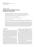
Figure 1: The contact center location was expressed relative to a
subject-specific scapula coordinate system. The axes of the scapula
coordinate system are aligned in the anterior/posterior (X axis),
superior/inferior (Y axis), and medial/lateral (Z axis) directions.
models using custom software (based on Open Inventor
5.0, Mercury Computer Systems, Chelmsford, Mass, USA)
that was developed to locate specific anatomical landmarks
and construct standardized anatomical coordinate systems
(Figure 1)[17]. To minimize side-to-side variability in
kinematic measures due solely to anatomical axis locations,
the same anatomical landmark locations identified on the
humerus and scapula of the repaired shoulder were used for
the contralateral shoulder. This was accomplished by mirror-
imaging the contralateral shoulder CT-based bone models,
manually coregistering these bone models with the repaired
shoulder’s CT-based bone models, and then transferring
the anatomical landmark locations to the contralateral
shoulder’s CT-based bone models. Rotations of the humerus
relative to the glenoid were calculated using a standard Euler
angle sequence in which the first rotation defined the plane
of elevation, the second rotation described the amount of
elevation, and the third rotation represented the amount of
internal/external rotation [18].
2.5. Measuring Glenohumeral Joint Contact Patterns. Gleno-
humeral joint contact patterns were determined by com-
bining the joint motion measured from the biplane X-ray
images with the subject-specific CT bone models. Br iefly, the
CT-based bone models were first converted into 3D surface
models constructed of contiguous triangular tiles. A typical
humerus or s capula model contained approximately 70 000
triangles of 0.5 mm
2
each. To avoid unnecessary calculation,
two specific regions of interest were identified: the humeral
head and the glenoid. After co-registering the surface models
with the kinematic data, the custom software calculated
the 3D distance from ever y surface-triangle centroid on
the humeral head to every surface-triangle centroid on
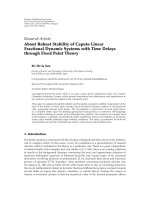
the glenoid (Figure 2(a)). The contact center location was
then determined by calculating the centroid of the closest
200 mm
2
region of contact between the humerus and glenoid
(Figure 2(b)). The 3D coordinates of this contact center
EURASIP Journal on Advances in Signal Processing 3
2 mm
6 mm
(a)
2 mm
6 mm
(b)
Figure 2: (a) Colormap of the minimum distance between the
glenoid and humerus for a single frame of data. (b) The contact
center location (indicated by the black dot) was calculated as the
centroid of the closest 200 mm
2
region between the humerus and
glenoid.
location were then expressed relative to the scapula-based
coordinate system, with the medial/lateral coordinate always
located on the glenoid surface. This process was repeated
for all frames of every trial. These calculations resulted in a
3D contact path, that is, a time-series of glenohumeral joint
contact data at each point in time.
Due to differences in glenoid size between subjects, these
glenohumeral joint contact data were normalized relative
the size of each subject’s glenoid. Specifical ly, we first used
custom software developed in our laboratory to manually
measure the glenoid’s maximum superior/inferior (S/I) and
maximum anterior/posterior (A/P) dimensions from the
CT-based bone models. For each subject, the 3D joint contact
center coordinates were then normalized by (1) dividing
the A/P contact center location by the maximum A/P
glenoid dimension, and (2) dividing the S/I contact center
location by the maximum S/I glenoid dimension. Thus,
the data were expressed as a percentage of the maximum
glenoid dimensions in both the A/P and S/I directions.
These normalized contact center position data were then
averaged across subjects in 5
◦
increments from 10
◦
to 70
◦
of
glenohumeral abduction.
2.6. Outcome Measures. To quantif y d ifferences in joint
contact patterns between the repaired and contralateral
shoulders, we calculated five outcome measures from the
Post
ANT
–50
–50
–100
–25
–25
–75
25 50
Repaired shoulder
Asymptomatic, contralateral shoulder
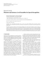
Figure 3: Average path of the glenohumeral joint contact center
(superimposed on a typical glenoid) during coronal-plane abduc-
tion. For each path, the open circle (
◦) indicates the starting
position and the closed circle (
•) indicates the ending position.
ANT: anterior, POST: posterior.
normalized 3D contact center data. These outcome mea-
sures, averaged across all trials, included A/P contact center
position, S/I contact center position, A/P contact position
range, S/I contact position range, and contact path length.
2.7. Statistical Analysis. We used a two-way repeated mea-
sures ANOVA to assess the effects of glenohumeral joint
abduction angle (from 10
◦
to 70
◦
in 10
◦
increments) and
shoulder condition (repaired versus contralateral) on the
normalized A/P and S/I contact center position. The effect of
shoulder condition (repaired versus contralateral) on average
A/P contact center position, average S/I contact center
position, A/P contact position range, S/I contact position
range, and contact path length was assessed with a paired t-
test. Significance was set at P<.05.
3. Results
The experimental technique presented here was sufficiently
sensitive to detect differences in joint contact patterns as
a function of both abduction angle and shoulder condi-
tion (i.e., repaired versus contralateral). The joint contact
center position moved predominantly in the S/I direction
and relatively little in the A/P direction during shoulder
abduction in both the repaired and contralateral shoulders
(Figure 3), with abduction angle having a significant effect
on S/I contact center position (P
= .004) but not A/P
contact center position (P
= .675). Interestingly, the
path of the joint contact center changed direction during
abduction in the repaired shoulders. Specifically, the joint
contact center location moved superiorly on the glenoid
4 EURASIP Journal on Advances in Signal Processing
Post
ANT
–50
–50
–100
–25
–25
–75
25 50
Repaired shoulder
Asymptomatic, contralateral shoulder
Figure 4: Average contact center position from 10
◦
to 70
◦
of
coronal-plane abduction. Significant differences in both the average
S/I (P
= .01) and A/P (P = .04) contact center position were
detected between the repaired and contralateral shoulders. ANT:
anterior, POST: posterior.
from 10
◦
to 40
◦
of glenohumeral abduction, but then moved
inferiorly on the glenoid from 40
◦
to 70
◦
of abduction
(Figure 3). Consequently, the distance between the joint
contact center locations associated with the repaired shoul-
ders’ starting position (10
◦
of glenohumeral abduction) and
ending position (70
◦
of glenohumeral abduction) was only
1.5 mm. In contrast, the distance between the joint contact
center locations at the starting and ending positions in
the contralateral shoulders was 5.4 mm as the joint contact
center path did not change direction during abduction.
Shoulder condition (i.e., repaired versus contralateral)
had a significant effect on b oth the S/I (P<.001) and A/P
(P
= .029) contact center position. Specifically, the repaired
shoulders’ average joint contact center was 12.1%
± 6.4%
higher on the glenoid (P
= .01) and 3.7% ± 2.5% more
anterior on the glenoid (P
= .04) than the contralateral
shoulders’ average joint contact center (Figure 4). However,
the study did not detect statistically significant differences
between the repaired and contralateral shoulders in terms
of A/P contact center range (P
= .18, Figure 5), S/I contact
center range (P
= .10, Figure 5), or contact path length
(P
= .89, Figure 5).
4. Discussion
This study describes a technique for measuring in vivo
glenohumeral joint contact patterns during dynamic activ-
ities, and demonstrates application of this technique by
characterizing differences between repaired and contralateral
shoulders of patients who have undergone rotator cuff repair.
The experimental method described here offers advantages
Distance (mm)
A/P range of
contact path
S/I range of
contact path
Contact path
length
Repaired shoulder
0
2
4
6
8
10
12
14
16
Asymptomatic, contralateral shoulder
P = .18
P = .1
P = .89
Figure 5: No statistically significant differences were detected
between the repaired and contralateral shoulders in terms of A/P
contact center position range (P
= .18), S/I contact center position
range (P
= .10), or contact path length (P = .89).
over conventional techniques for describing glenohumeral
joint motion. Specifically, glenohumeral joint contact pat-
terns provide a measure of joint function that may not
be adequately captured when reporting only conventional
measures of humeral rotation and translation. This is
important, since many pathologic conditions of the shoulder
(e.g., rotator cuff tear, glenohumeral joint instability) are
believed to alter the glenohumeral joint articular mechanics,
and procedures for treating these common conditions rely
implicitly on the belief that restoring normal glenohumeral
joint mechanics is necessary to obtain a satisfactory outcome.
The approach described here of quantifying joint contact
patterns has also been used by other investigators as a
means of detecting functional differences associated with a
specific clinical condition (e.g., distal radius malunion [19,
20]) that can not be detected using conventional kinematic
parameters. Thus, joint contact patterns are perhaps not only
a more sensitive measurement than conventional kinematics
for detecting subtle differences in joint function but may also
provide a more clinically relevant indication of the extent to
which a conservative or surg ical procedure has adequately
restored normal joint function.
Glenohumeral joint contact patterns have been quan-
tified in a number of cadaveric studies. For example, the
effects of shoulder position on glenohumeral joint contact
patterns have been studied in cadaver specimens using
stereophotogrammetry [21–23]. Soslowsky et al. indicated
that the glenoid contact location was primarily in the
anterior half of the glenoid with the shoulder adducted,
but moved posteriorly with increasing abduction [23]. In
contrast, the current study demonstrated that the contact
center was a lways located on the posterior half of the glenoid
(in both the repaired and contralateral shoulders), and that
there was little change in the A/P contact center location
with increasing abduction. Furthermore, while the current
EURASIP Journal on Advances in Signal Processing 5
study demonstrated significant changes in the S/I contact
center location with increasing abduct ion (Figure 3), the
study by Soslowsky et al. reported no clear shift in the
S/I direction in glenoid contact patterns with abduction.
One plausible explanation that may help to reconcile these
differences is that these previous cadaveric studies simulated
scapular-plane abduction whereas the subjects in the current
study elevated their shoulders in the coronal plane. Cadav-
eric studies have also investigated the effects of shoulder
position, joint contact forces, muscles forces, and various
simulated clinical conditions on joint contact area and joint
contact pressures by inserting thin pressure-sensitive films or
similar devices (e.g., Fuji film or Tekscan sensors) between
the humerus and glenoid [1–3, 24, 25]. Although these
types of cadaveric experiments have provided the bulk of
existing knowledge about glenohumeral joint mechanics,
cadaveric studies are not capable of accurately reproducing
the complex muscle forces, joint forces, or joint motions that
occur in vivo. Furthermore, given that rotator cuff disease
typically develops slowly over many years, the inability to
study biological response or disease progression is another
significant limitation of cadaver studies.
One limitation of this technique for measuring joint
contact patterns is that it neglects cartilage, since carti-
lage is difficult to image with both CT and conventional
radiography. DeFrate and colleagues have suggested that
neglecting cartilage could potentially lead to erroneous
measures of joint contact in the knee due to variations in
cartilage thickness across the femur and tibia [26]. Previous
research has demonstrated that cartilage thickness varies
with position on the glenoid and humeral h ead too, but that
cartilage thickness has an inverse relationship b etween these
articulating surfaces [27–30]. In particular, it has been shown
that cartilage thickness for the humeral head is highest in
the center and lowest at the periphery. In contrast, cartilage
thickness on the glenoid is lowest in the center of the
glenoid and higher at the periphery. The significance of this
inverse relationship is that based on the data by Soslowsky
and colleagues [27], the range of total cartilage thickness
(i.e., the sum of glenoid cartilage thickness and humeral
head cartilage thickness) over the regions of contact on the
glenoid and humeral head during coronal-plane abduction
varies by only 0.4 mm. Since the range of total cartilage
thickness is equal to the uncertainty associated with the
model-based tracking technique (
±0.4 mm [16]), the current
approach is not sufficiently accurate to detect changes
in joint contact associated with subtle variations in total
cartilage thickness. Thus, there is currently no advantage
to including cartilage information in our subject-specific
bone models. However, we anticipate additional technical
enhancements will improve the accuracy of our model-based
tracking technique, and therefore future efforts will focus on
developing and validating (under conditions that provide a
realistic simulation of in vivo testing conditions) a technique
that includes cartilage in the estimation of joint contact
patterns.
In summary, we have developed a technique for charac-
terizing in vivo glenohumeral joint contact patterns during
dynamic activities. This approach overcomes limitations
associated with cadaveric experiments and static imaging
techniques. Future research efforts will use this experimental
approach to objectively assess the glenohumeral joint contact
patterns in asymptomatic normal individuals and those with
pathologic conditions affecting the shoulder.
Acknowledgments
This project was supported by grant number AR051912 from
NIH/NIAMS.
References
[1] J. Yu, M. H. McGarry, Y S. Lee, L. V. Duong, and T. Q.
Lee, “Biomechanical effects of supraspinatus repair on the
glenohumeral joint,” Journal of Shoulder and Elbow Surgery,
vol. 14, no. 1, supplement 1, pp. S65–S71, 2005.
[2]R.GuptaandT.Q.Lee,“Positional-dependentchanges
in glenohumeral joint contact pressure and force: possible
biomechanical etiology of posterior glenoid wear,” Journal of
Shoulder and Elbow Surgery, vol. 14, no. 1, supplement 1, pp.
S105–S110, 2005.
[3] P.E.Greis,M.G.Scuderi,A.Mohr,K.N.Bachus,andR.T.
Burks, “Glenohumeral articular contact areas and pressures
following labral and osseous injury to the anteroinferior
quadrant of the glenoid,” Journal of Shoulder and Elbow
Surgery, vol. 11, no. 5, pp. 442–451, 2002.
[4] H. Graichen, S. Hinterwimmer, R. von Eisenhart-Rothe, T.
Vogl, K H. Englmeier, and F. Eckstein, “Effect of abducting
and adducting muscle acitivity on glenohumeral translation,
scapular kinematics and subacromial space width in vivo,”
Journal of Biomechanics, vol. 38, no. 4, pp. 755–760, 2005.
[5] S. Hinterwimmer, R. von Eisenhar t -Rothet, M. Siebert, et al.,
“Influence of adducting and abducting muscle forces on the
subacromial space width,” Medicine and Science in Sports and
Exercise, vol. 35, no. 12, pp. 2055–2059, 2003.
[6] G.P.Pappas,S.S.Blemker,C.F.Beaulieu,T.R.McAdams,S.
T. Whalen, and G. E. Gold, “In vivo anatomy of the Neer and
Hawkins sign positions for shoulder impingement,” Journal of
Shoulder and Elbow Surgery, vol. 15, no. 1, pp. 40–49, 2006.
[7] C. M. L. Werner, D. Weishaupt, S. Blumenthal, A. Curt, P.
Favre, and C. Gerber, “Effect of experimental suprascapular
nerve block on active glenohumeral translation in vivo,”
Journal of Orthopaedic Research, vol. 24, no. 3, pp. 491–500,
2006.
[8] H. Graichen, T. Stammberger, H. Bonel, E. Karl-Hans, M.
Reiser, and F. Eckstein, “Glenohumeral translation during
active and passive elevation of the shoulder—a 3D open-MRI
study,” Journal of Biomechanics, vol. 33, no. 5, pp. 609–613,
2000.
[9]M.Mahfouz,G.Nicholson,R.Komistek,D.Hovis,andM.
Kubo, “In vivo determination of the dynamics of normal, rota-
tor cuff-deficient, total, and reverse replacement shoulders,”
Journal of Bone and Joint Surgery A, vol. 87, supplement 2, pp.
107–113, 2005.
[10] C. W. A. Pfirrmann, M. Huser, G. Szekely, J. Hodler, and C.
Gerber, “Evaluation of complex joint motion with computer-
based analysis of fluoroscopic sequences,” Investigative Radiol-
ogy, vol. 37, no. 2, pp. 73–76, 2002.
[11] I. S. Talkhani and C. P. Kelly, “Movement analysis of asymp-
tomatic normal shoulders: a preliminary study,” Journal of
Shoulder and Elbow Surgery, vol. 10, no. 6, pp. 580–584, 2001.
6 EURASIP Journal on Advances in Signal Processing
[12] D. G. Mandalidis, B. S. Mc Glone, R. F. Quigley, D. McInerney,
and M. O’Brien, “Digital fluoroscopic assessment of the
scapulohumeral rhythm,” Surgical and Radiologic Anatomy,
vol. 21, no. 4, pp. 241–246, 1999.
[13]J P.Baeyens,P.VanRoy,A.DeSchepper,G.Declercq,and
J P. Clarijs, “Glenohumeral joint kinematics related to minor
anterior instability of the shoulder at the end of the late
preparatory phase of throwing,” Clinical Biomechanics, vol. 16,
no. 9, pp. 752–757, 2001.
[14] I. K. Y. Lo and S. S. Burkhart, “Double-row arthroscopic
rotator cuff repair: re-establishing the footprint of the rotator
cuff,” Arthroscopy, vol. 19, no. 9, pp. 1035–1042, 2003.
[15] S. Tashman and W. Anderst, “In-vivo measurement of
dynamic joint motion using high speed biplane radiography
and CT: application to canine ACL deficiency,” Journal of
Biomechanical Engineering, vol. 125, no. 2, pp. 238–245, 2003.
[16] M. J. Bey, R. Zauel, S. K. Brock, and S. Tashman, “Validation
of a new model-based tracking technique for measuring three-
dimensional, in vivo glenohumeral joint kinematics,” Journal
of Biomechanical Engineering, vol. 128, no. 4, pp. 604–609,
2006.
[17]G.Wu,F.C.T.vanderHelm,H.E.J.Veeger,etal.,“ISB
recommendation on definitions of joint coordinate systems of
various joints for the reporting of human joint motion—part
II: shoulder, elbow, wrist and hand,” Journal of Biomechanics,
vol. 38, no. 5, pp. 981–992, 2005.
[18] A. R. Karduna, P. W. McClure, L. A. Michener, and B. Sen-
nett, “Dynamic measurements of three-dimensional scapular
kinematics: a validation study,” Journal of Biomechanical
Engineering, vol. 123, no. 2, pp. 184–190, 2001.
[19] J.J.Crisco,D.C.Moore,G.E.Marai,etal.,“Effects of distal
radius malunion on distal radioulnar joint mechanics—an in
vivo study,” Journal of Orthopaedic Research, vol. 25, no. 4, pp.
547–555, 2007.
[20] G. E. Marai, D. H. Laidlaw, C. Demiralp, S. Andrews, C. M.
Grimm, and J. J. Crisco, “Estimating joint contact areas and
ligament lengths from bone kinematics and surfaces,” IEEE
Transactions on Biomedical Engineering, vol. 51, no. 5, pp. 790–
799, 2004.
[21] G. A. Ateshian, S. D. Kwak, L. J. Soslowsky, and V. C. Mow,
“A stereophotogrammetric method for determining in situ
contact areas in diarthrodial joints, and a comparison with
other methods,” Journal of Biomechanics,vol.27,no.1,pp.
111–124, 1994.
[22] R. Kelkar, V. M. Wang, E. L. Flatow, et al., “Glenohumeral
mechanics: a study of articular geometry, contact, and kine-
matics,” Journal of Shoulder and Elbow Surgery,vol.10,no.1,
pp. 73–84, 2001.
[23] L. J. Soslowsky, E. L. Flatow, L. U. Bigliani, R. J. Pawluk, G. A.
Ateshian, and V. C. Mow, “Quantitation of in situ contact areas
at the glenohumeral joint: a biomechanical study,” Journal of
Orthopaedic Research, vol. 10, no. 4, pp. 524–534, 1992.
[24] J.J.P.Warner,M.K.Bowen,X H.Deng,J.A.Hannafin,S.
P. Arnoczky, and R. F. Warren, “Articular contact patterns of
the normal glenohumeral joint,” Journal of Shoulder and Elbow
Surgery, vol. 7, no. 4, pp. 381–388, 1998.
[25] R.A.Creighton,B.J.Cole,G.P.Nicholson,A.A.Romeo,and
E. P. Lorenz, “Effectoflateralmeniscusallograftonshoulder
articular contact areas and pressures,” Journal of Shoulder and
Elbow Surgery, vol. 16, no. 3, pp. 367–372, 2007.
[26] L. E. DeFrate, H. Sun, T. J. Gill, H. E. Rubash, and G. Li, “In
vivo tibiofemoral contact analysis using 3D MRI-based knee
models,” Journal of Biomechanics, vol. 37, no. 10, pp. 1499–
1504, 2004.
[27] L. J. Soslowsky, E. L. Flatow, L. U. Bigliani, and V. C.
Mow, “Articular geometry of the glenohumeral joint,” Clinical
Orthopaedics and Related Research, no. 285, pp. 181–190, 1992.
[28]J.Hodler,R.A.Loredo,C.Longo,D.Trudell,J.S.Yu,and
D. Resnick, “Assessment of articular cartilage thickness of
the humeral head: MR-anatomic correlation in cadavers,”
American Journal of Roentgenology, vol. 165, no. 3, pp. 615–
620, 1995.
[29] H. Graichen, J. Jakob, R. von Eisenhart-Rothe, K H.
Englmeier, M. Reiser, and F. Eckstein, “Validation of cartilage
volume and thickness measurements in the human shoulder
with quantitative magnetic resonance imaging,” Osteoarthritis
and Cartilage, vol. 11, no. 7, pp. 475–482, 2003.
[30] L. Yeh, S. Kwak, Y S. Kim, et al., “Evaluation of articular
cartilage thickness of the humeral head and the glenoid
fossa by MR arthrography: anatomic correlation in cadavers,”
Skeletal Radiology, vol. 27, no. 9, pp. 500–504, 1998.