Parallel Manipulators Towards New Applications Part 13 ppt
Bạn đang xem bản rút gọn của tài liệu. Xem và tải ngay bản đầy đủ của tài liệu tại đây (2.98 MB, 30 trang )
A Reconfigurable Mobile Robots System Based on Parallel Mechanism
353
The homogeneous transformation matrix [T] from the world coordinate OXYZ to the
coordinate O’X’Y’Z’ is described as (6).
⎥
⎥
⎥
⎦
⎤
⎢
⎢
⎢
⎣
⎡
−
⋅
⎥
⎥
⎥
⎦
⎤
⎢
⎢
⎢
⎣
⎡
−⋅
⎥
⎥
⎥
⎦
⎤
⎢
⎢
⎢
⎣
⎡
−
==
100
0
0
0
0
001
0
010
0
)()()(
zz
zz
yx
x
yy
yy
cs
sc
cs
xsc
cs
sc
ZRotXRotYRotT
θθ
θθ
θθ
θθ
θθ
θθ
(6)
After the reconfiguring movement, A, B, C, and D are changed to new positions described as
A
1
, B
1
, C
1
, and D
1
. The Cartesian coordinates of the new points can be expressed as (7) and
(8).
])[(][
11
BAZRotBA
=
(7)
[
]
[
]
DCTDC =
11
(8)
There are some constraints to the mechanical structure, as shown in (9) and (10). The lengths
of the link L
1
and L
2
are equal to the distance between C
1
A
1
and D
1
B
1
respectively.
111
ACL
−
=
(9)
112
BDL −=
(10)
All these results are inserted into (9) and (10), then the kinematics expression results from
them.
2
2
2
2
1
))(
)((
))()((
)
)(
)((
yxzyxzy
zyxzy
zzxzxzx
zzyx
zyxyz
zyxzy
cLcccsssK
scscsK
KcKsLsccKscK
KsKcsLc
csscsK
sssccKL
θθθθθθθ
θθθθθ
θθθθθθθ
θθθθ
θθθθθ
θθθθθ
++
−+−+
+−−−
+−−
++−
−+=
(11)
2
2
2
2
2
))(
)((
))()((
)
)(
)((
yxZYXZY
ZYXZY
zzxzxzx
ZZyx
zyxyz
zyxzy
cLcccsssK
scscsK
KcKsLsccKscK
KsKcsLc
csscsK
sssccKL
θθθθθθθ
θθθθθ
θθθθθθθ
θθθθ
θθθθθ
θθθθθ
++
++−+
−−−+
++−
++−
++=
(12)
Named T
L1
=L
1
1/2
, T
L2
=L
2
1/2
, then the relation between q and θ can be concluded as (13).
q = [T
L1
1/2
, T
L2
1/2
, θ
Z
]
T
(13)
The relationship of the world coordinate and the reference joint coordinate can be
concluded. Furthermore the movements can be anticipated according to the joints’ driving
outputs.
Parallel Manipulators, Towards New Applications
354
4. System realization
4.1 Mechanical realization
The JL-I system consists of three connected, identical modules for crossing grooves, steps,
obstacles and traveling in complex environment. The mechanical structure is flexible due to
its uniform modules and special connection joints (Fig. 6a). Actually each module is an
entire robot system that can perform distributed activities (Fig. 6b).
(a) (b)
Fig. 6. The robotics system of JL-I
Fig. 7. An artistic impression of the module
A Reconfigurable Mobile Robots System Based on Parallel Mechanism
355
The single module is about 35 centimeters long, 25 centimeters wide and 15 centimeters
high. Fig. 7 shows the mechanical structure of the module which has two powered tracks, a
serial mechanism, a parallel mechanism, and a docking mechanism. Two DC motors drive
the tracks providing skid-steering ability in order to realize the flexible omni-directional
movement. The docking mechanism consists of two parts: a cone-shaped connector at the
front and a matching coupler at the back of the module. It enables any two adjacent modules
to link, forming a train configuration.
4.1.1 Realizing the parallel mechanism
The realization of the parallel mechanism is also shown in Fig. 8. Each branch of it consists
of a driving platform, a Hooker joint, a lead screw, a nut slider, a ball bearing, a
synchronous belt system, a DC motor and a base platform. The Hooker joint connects the
driving platform and the nut slider. The lead screw is supported by a ball bearing in the
base platform. The cone-shaped connector fixed on the driving platform is called a buffer
head, because its rubber is used to buffer the wallop during the docking process. Besides the
two branches, there is a knighthead fixed on the base platform and connected to the driving
platform by another Hooker joint. By revolving the two lead screws, the driving platform
can be manipulated relative to the Hooker joint on the knighthead.
Fig. 8 The parallel mechanism
There are two advantages in applying the synchronous belt system.
a) When the screw revolves, it rocks around the ball bearing. By using the synchronous
belt system and an elastic connector, the rock motion of the screw is isolated from the
motor.
b) The motor and the lead screw can be installed on the same side of the base platform,
and that decreases the dimension of the structure.
4.1.2 Realizing the serial and docking mechanism
The docking mechanism consists of two parts: a cone-shaped connector at the front (shown
in Fig. 8) and a matching coupler at the back of the module, as shown in Fig. 9. The coupler
is composed of two sliders propelled by a motor-driven screw. The sliders form a matching
Parallel Manipulators, Towards New Applications
356
funnel which guides the connector to mate with the cavity and enables the modules to self-
align with certain lateral offsets and directional offsets. After that, two mating planes
between the sliders and the cone-shaped connector constrain the movement, thus locking
the two modules. This mechanism enables any two adjacent modules to link, forming a train
configuration. Therefore the independent module has to be rather long in order to realize all
necessary docking functions. In designing this mechanism and its controls, the equilibrium
between flexibility and size has to be reached. A DC motor is connected to the coupler with
its motor shaft aligned with the module’s Z axis, which also passes through the center of the
Hooker joint on the knighthead of the parallel mechanism. Therefore a full active spherical
joint is formed when two modules are linked.
Fig. 9. The serial and docking mechanism
This docking mechanism can compensate a position deviation within ±30mm and a posture
deviation within ±45° between two modules. The self-locking characteristic of the screw-nut
mechanism ensures a reliable connection between two modules to endure the vibration in
motion.
4.2 Control system
The control system of the robot based on an industrial PC (IPC) and a master-slave structure
meets the requirements of functionality, extensibility, and easy handling (Fig. 10). Multiple
processes programming capability is guaranteed by the principle of the control structure.
The hardware consists of an SBC-X255, an independent image processing unit and a low-
level driving unit (SBC 2).
The SBC-X255 is the core part of the control system. It is a standard PC/104+ compliant,
single-board computer with an embedded low power Intel Xscale PXA255 (400 MHz). This
board operates without a fan at temperatures from -40° C up to 85° C and typically
consumes fewer than 4.5 Watts while supporting numerous peripherals. The Ethernet port
is used as a communication interface between the IPC and the image processing unit which
is in charge of searching and monitoring. The IPC is a higher-level controller and does not
take part in joint motion control. Its responsibilities include receiving orders from the
remote controller, planning operational processes, receiving feedback information.
The SBC 2 is in charge of driving five DC motors and receives and processes all related
sensor signals. It can directly count the pulse signals from the encoder, deal with the signals
A Reconfigurable Mobile Robots System Based on Parallel Mechanism
357
from other magnetic sensors, and directly drive the DC motors forward and backward at
different velocities. Meanwhile it sends all information to the IPC through another Ethernet
port.
Fig. 10. The control system of JL-1’s module
There are two kinds of external sensors on the robot: a CCD camera and touchable sensors,
which are responsible for collecting information about the operational environment. The
internal sensors such as GPS, digital compass, gyro sensors are used to reflect the self-status
of the robot. The gesture sensor will send the global locomotion information of the robot θx,
θy, and θz to the controller, which are essential to inverse kinematics. Meanwhile there are
limit switches to give the controller the position of the joint. On the joint where the accurate
position is needed, the optical encoder is used.
5. On-site tests
Relevant successful on-site tests with the mobile robot were carried out recently, confirming
the principles described above and the robot’s ability. Fig. 11 shows the docking process of
the connection mechanism whose most distinctive features are its ability of self aligning and
its great driving force. With the help of the powered tracks, the cone-shaped connector and
the matching coupler can match well within ±30mm lateral offsets and ±45°directional
offsets.
Parallel Manipulators, Towards New Applications
358
Fig. 11. The docking process
Compared with many configurable mobile robots, the JL-I improves its flexibility and
adaptability by using novel active spherical joints between modules. The following figures
show the typical motion functionalities one by one, whose principles are discussed above.
Fig. 12. Climbing stairs
(1) (2) (3)
(4) (5) (6)
Fig. 13. Snapshots of crossing a step
(1) (2) (3)
(4) (5) (6)
Fig. 14. Snapshots of the 90° self-recovery
A Reconfigurable Mobile Robots System Based on Parallel Mechanism
359
(1) (2) (3)
(4) (5) (6)
Fig. 15. Snapshots of the 180° self-recovery
The experimental results show that the 3 DOF active joints with serial and parallel
mechanisms have the ability to achieve all the desired configurations. The performance
specifications of JL-I are given in Table 1.
Parameters Values
Posture adjustment angle around X-axis ±45°
Posture adjustment angle around Y-axis ±45°
Posture adjustment angle around Z-axis 0~360°
Maximum lateral docking offset ±30 mm
Maximum directional docking offset ±45°
Maximum height of steps 280 mm
Maximum length of ditches 500 mm
Minimum width of the fence 200 mm
Maximum slope angle 40°
Self-recovering ability 0~180°
Maximum climbing velocity 180 mm/s
Maximum unchangable working time 4 hours
Table 1. Performance specifications
Parallel Manipulators, Towards New Applications
360
6. Conclusions
The modular reconfiguration robot has the ability of changing its configuration which
makes it more suitable for complex environments. In contrast to conventional theoretical
research, the project introduced in this paper successfully completes the following
innovative work.
a) It proposes a robot named JL-I which is based on a modular reconfiguration concept.
The advantages and the characteristics of the mechanism are analysed. The robot
features a docking mechanism with which the modules can connect or disconnect
flexibly. The active spherical joints formed by serial and parallel mechanisms endow the
robot with the ability of changing shapes in three dimensions.
b) A kinematics model of reconfiguration between two modules is given. The relationship
of the world coordinate and the reference joint coordinate is concluded. Furthermore,
the movements can be anticipated according to the joints’ driving outputs. The analysed
results are important for system design and the design of the controlling mechanism for
the robot.
c) Experimental tests have shown that the JL-I can implement a series of various
locomotion capabilities such as 90° recovery, 180° recovery, and crossing steps. This
implies the mechanical feasibility, the rationality of the analysis and the outstanding
movement adaptability of the robot.
The future research will focus on the following aspects.
a) Developing a new docking mechanism which tolerates larger offset in rugged terrain
and can be used as a simple manipulator;
b) Developing a more reliable track modules with shock absorption function;
c) Developing a new mechanism which can actively undock a disable robot module.
7. Acknowledgement
The work in this chapter is proposed by National High-tech R&D Program (863 Program) of
China (No. 2006AA04Z241).
8. Reference
Granosik, G.; Hansen, M. G. & Borenstein, J. (2005). The omnitread serpentine robot for
industrial inspection and surveillance. Industrial Robot: An International Journal,
Vol.32, No.2, (Feb. 2005) page numbers (139-148), ISSN: 0143-991X
Castano, A.; Shen, W.M. & Will, P. (2000). CONRO: towards miniature self-sufficient
metamorphic robots. Autonomous Robots, Vol.13, No.4, (April 2000) page numbers
(309-324), ISSN: 0929-5593
Rus, D. & Vona, M. (2000). A basis for self reconfigurable robots using crystal modules,
Proceedings of the 2000 IEEE Conference on Intelligent Robots and Systems, pp.
2194-2202, ISBN: 0-7803-6348-5 Takamatsu, Japan, October 2000, IEEE Service
Center, Piscataway
Suzuki, Y.; Inou, N.; Kimura, H & Koseki, M. (2007). Reconfigurable group robots
adaptively transforming a mechanical structure. Proceedings of the 2007 IEEE/RSJ
International Conference on Intelligent Robots and Systems, pp. 2361-2367, ISBN: 1-
A Reconfigurable Mobile Robots System Based on Parallel Mechanism
361
4244-0912-8, San Diego, CA, USA, Oct. 29 – Nov. 2, 2007, IEEE Service Center,
Piscataway
Kamimura, A.; Kurokawa, H.; Yoshida, E.; Murata, S.; Tomita, K. & Kokaji, S. (2005).
Automatic locomotion design and experiments for a modularrobotic system,
IEEE/ASME Transactions on Mechatronics, Vol. 10, No. 3, (March 2005) page
numbers (314-325), ISSN: 1083-4435
Shen, W M.; Salemi B. & Will, P. (2002). Hormone-Inspired adaptive communication and
distributed control for CONRO self-reconfigurable robots. IEEE Transactions on
Robotics and Automation, Vol. 18, No. 4, (Oct. 2002) page numbers (700-712), ISSN:
0882-4967
Suzuki, Y.; Inou, N.; Kimura, H. & Koseki, M. (2006). Reconfigurable group robots
adaptively transforming a mechanical structure – Crawl motion and adaptive
transformation with new algorithms. Proceedings of IEEE Internatioanl Conference on
Intelligent Robots and Systems (IROS 2006), pp. 2200-2205, ISBN: 1-4244-0259-X,
Beijing, China, October 2006, IEEE Service Center, Piscataway
Vassilvitskii, S.; Yim, M. & Suh, J. (2002). A complete, local and parallel reconfiguration
algorithm for cube style modular robots, Proceedings of the 2002 IEEE International
Conference on Robotics & Automation, pp. 117- 122 ISBN: 0-7803-7272-7, Washington
DC, USA, May 2002, IEEE Service Center, Piscataway
Hirose, S. & Morishima, A. (1990). Design and control of a mobile robot with an articulated
body. The International Journal of Robotics Research, Vol. 9 No. 2, (Feb. 1990) page
numbers (99-113), ISSN: 0278-3649
Klaassen, B. & Paap, K.L. (1999). GMD-SNAKE2: a snake-like robot driven by wheels and a
method for motion control. Proceedings of the 1999 IEEE International Conference on
Robotics and Automation, pp. 3014 - 3019, ISBN: 0792356012, Detroit, MI, USA, May
1999, IEEE Service Center, Piscataway
Yim, M. & David, G. (2000). PolyBot: a module reconfigurable robot. Proceedings of the 2000
IEEE International Conference on Robotics and Automation, pp.514-520, ISBN: 0-7803-
5886-4, San Francisco, CA, USA, April 2000, IEEE Service Center, Piscataway
Takayama, T. & Hirose, S. (2000). Development of Souryu-I connected crawler vehicle for
inspection of narrow and winding space, Proceedings of the 26th Annual Conference of
the IEEE Industrial Electronics Society, pp. 143-148 ISBN: 0-7803-6456-2, Nagoya,
Aichi, Japan, Oct. 2000, IEEE Service Center, Piscataway
Brown, H. B. & et al. (2002). Millibot trains for enhanced mobility. IEEE/ASME Transactions
on Mechantronics, Vol.7, No.4, (March 2002) page numbers (452-461), ISSN: 1083-
4435
Park, M.; Chung W. & Yim M. (2004). Control of a mobile robot with passive multiple
trailers. Proceedings of the 2004 IEEE International Conference on Robotics and
Automation, pp. 4369-4374, ISBN: 0-7803-8232-3, New Orleans, LA, United States,
April-May 2004, IEEE Service Center, Piscataway
Sahin, E.; Labella, T.H. & et al. (2002). SWARM-BOT: Pattern formation in a swarm of self-
assembling mobile robots. Proceedings of the 2002 IEEE International Conference on
Systems, Man and Cybernetics, pp. 145-150, ISBN: 0-7803-7437-1, Yasmine
Hammamet, Tunisia, October 2002, IEEE Service Center, Piscataway
Parallel Manipulators, Towards New Applications
362
Zhang, H.X.; Wang, W.; Deng, Z.C. & Zong, G.H. (2006). A novel reconfigurable robot for
urban search and rescue. International Journal of Advanced Robotic Systems, Vol.3
No.4 (2006), page numbers (259-366), ISSN: 1729-8806
Wang, W.; Zhang H.X; Zong, G.H. & Zhang, J.W. (2006). Design and realization of a novel
reconfigurable robot with serial and parallel mechanisms. Proceedings of 2006 IEEE
International Conference on Robotics and Biomimetics, pp. 697-702, ISBN: 1-4244-0571-8,
Kunming, China, Dec. 2006, IEEE Service Center, Piscataway
17
Hybrid Parallel Robot for the
Assembling of ITER
Huapeng Wu, Heikki Handroos and Pekka Pessi
Lappeenranta University of Technology
Finland
1. Introduction
The international thermonuclear experimental reactor (ITER) is a joint international research
and development project that aims to demonstrate the scientific and technical feasibility of
fusion power. The reactor tokomak (vacuum vessel) is made of stainless steel, and contains
nine sectors welded together; each sector has about the size of 10 meter high and 6 meter
wide. The sectors of ITER vacuum vessel (VV) (Fig. 1) require more stringent tolerance
(±5mm) than normally expected for the size of the structure involved. The walls (inner wall
and outer wall) of ITER sectors are of 60mm thick and are joined by high quality leak tight
welds. In addition to the initial vacuum vessel assembly, the sectors may have to be
replaced for repair. Meanwhile, the machining operations and lifting of a possible e-beam
gun column system require extreme stiffness property and good accuracy for a machine
tool. The payload to weight ratio also has to be significantly better than it is in the
commercial industrial robots.
The conventional robots, providing a high nominal payload, are lack of stiffness and
accuracy in such machining condition. Since commercially available machines capable of
handling large payloads require floor mounting and their workspaces are insufficient for
reaching the cross section at a single mounting position, a special robot is needed. Parallel
robots have high stiffness, high dynamic performance and good payload to weight ratio in
comparison with the conventional serial robots. Stewart [1] presented the novel idea of six-
degree-of-freedom parallel robot in 1960’s. A remarkable number of research articles and
books about parallel manipulators have been published during the last two decades. There
are also a number of successful industrial applications developed [2], [3], [4], [7]. The
parallel manipulators have many potential advantages compared with the conventional
serial link manipulators. Parallel manipulators are closed-loop mechanism presenting good
performances in terms of accuracy, rigidity, high speed, and ability to handle large loads.
They are becoming popular in applications such as machining, welding, assembly, flight
and vehicle simulators, mining machines, and pointing devices [2], [3], [4], [7]. The most
important drawback of parallel robots is the small workspace, which can be made larger by
adding additional serial axes in the robot.
For the assembly of the ITER vacuum vessel sector, the precise positioning of welding end-
effectors at some distance in a confined space from the available supports will be required,
Parallel Manipulators, Towards New Applications
364
while it is not possible using conventional machines or robots. The parallel robot presented
in this paper is able to carry out welding and machining processes from inside the ITER
vacuum vessel, consisting of a six degree-of-freedom parallel mechanism mounted on a
carriage driven by electric motor/gearbox on a rack. The robot carries both welding gun
(such as a TIG, hybrid laser or e-beam welding gun to weld the inner and outer walls of the
ITER vacuum vessel sectors) and machining tools (to cut and mill the walls with necessary
accuracy). It can also carry other heavy tools and parts to a required position inside the
vacuum vessel.
The robot offers not only a device but also a methodology for assembling and repairing VV.
For assembling, an on-line six-degree-of-freedom-seam-finding algorithm has been
developed. The algorithm enables the robot to find welding seam automatically in a very
complex environment. For machining, the multi flexible machining processes carried out
automatically by the robot have also been investigated, including edge cutting, smoothing,
and defect point milling. The kinematic design of the robot has been optimised for the ITER
access and a hydraulically actuated prototype has been built. Finally the experimental
results are presented and discussed. The earlier development phases of the robot are
presented in [8] and [9].
2. Structure of VV and assembling process
The inner and outer walls of the VV of ITER are made of 60mm-thick stainless steel 316L
and are welded together through an intermediate, so-called “splice plate”, inserted between
the sectors to be joined. The splice plates have two important functions: (i) to allow access to
bolt together the thermal shield between the VV and coils; and (ii) to compensate the
mismatch between adjacent sectors to give a good fit-up of the sector-sector butt weld. The
robot’s end-effector will have to pass through the inner wall splice plates opening to reach
the outer wall. As shown in Fig.1, the assembly and repairing processes have to be carried
out from inside the vacuum vessel.
Fig.1 ITER and VV sectors to be welded
Hybrid Parallel Robot for the Assembling of ITER
365
The assembly or repair will be performed according to four phases: cutting, edge machining
and smoothing, welding, and non-destructive tests (NDT) control. The robot will carry out
welding, machining, and inspecting inside the VV. The maximum robot force arises from
cutting. It can be up to 3kN.
Fig.2 The track rail mounted inside VV and robot on the track
In order that the robot can operate in the cross section of the vessel, a track is assembled
inside the sector. The track has a rack on one side of the rail and it is supported by manifolds
and beams (shown in Fig. 2). The robot driven on the rail carries out welding or machining
along the edge of the sector. After finishing the assembly of two sectors, the robot has to be
moved to the next sector where there is also a track assembled. After finishing the assembly
of all the sectors, the robot can be taken out via the port of VV.
3. Kinematics of parallel robot
3.1 Structure of parallel robot
The proposed parallel robot has ten degrees of freedom (Fig. 3). It consists of two relatively
independent sub-structures: (i) carriage, which provides four additional degrees of freedom,
i.e., rotation, linear motion, tilt rotation and tracking motion, and these four degrees are
added to enlarge the workspace and to offer high mobility; and (ii) the Hexa-WH parallel
mechanism driven by six hydraulic cylinders contributes six degrees of freedom for the end-
effector. Thus the robot is a hybrid redundant manipulator with four extra degrees of
freedom provided by serial kinematic links.
a). Carriage mechanism
The carriage mainly consists of 5 units. i) Carriage frame: The carriage frame is a complex
structure welded by multi-steel-plates, and it is able to carry high payload and offers
enough room to maintain mechanisms. Stiffness and weight are the most important
considerations in the design, and they have been optimized to achieve necessary stiffness
Parallel Manipulators, Towards New Applications
366
with light weight. ii) Tracking drive unit: The tracking drive unit consists of electric motor,
reduction unit CYCLO, V-shape bearing, and driving gear. The electric servo motor with
Fig. 3 Parallel robot
position feedback controller offers the high accurate motion. In order to output large torque
to drive the heavy mass and payload, the reduction unit CYCLO is added to the motor
to reduce speed and to transmit high torque to the driving gear. Two V-shaped wheels keep
the carriage on the tracking rail at right position to avoid the cross motion. Two drive units
are used in the carriage to offer enough torque in order to drive the robot and payload
around inside the VV. iii) Compensation mechanism: The compensation system is an important
unit that limits the backlash caused by the inaccurate assembling of the tracking rail and
compensates the distance changing between the wheels in bending area. As the shape of the
VV is very complicated, it is difficult to keep the tracking rails lying on the VV surface in the
accurate position. The position tolerance can be up to ±2mm. The distance of the coupled
wheels has to be adjusted to follow the changes of the rail, and all the wheels must touch the
parallel rails with certain force during motion; hence an adaptive distance compensation
system is needed and it should be able to undertake the summed weight of the robot and
the payload, when the robot is upside down at the top position insider VV. Since the total
Hybrid Parallel Robot for the Assembling of ITER
367
payload is very heavy, a hydraulic cylinder is applied to justify the compensation force
according to the position where the robot is located. Fig. 4 shows the compensation system,
where the upside is the tolerance adaptive mechanism that passively follows the changes of
track rail and the downside is the hydraulic distance compensation system that ensures a
constant force is applied to the rails. iv) Linear drive unit: The linear drive unit enlarges the
workspace of the robot, and consists of five parts: ball screw drive unit, servo motor, rails,
linear bearings, and a table. Two parallel rails are fixed on the carriage frame to offer the
motion crossing the frame and to extend the distance of the robot in direction Y. In direction
Y, the distance from the inner board to the outer board can be 900mm in one VV sector, i.e.,
the robot needs longer reach in this direction, and the linear drive unit helps the robot end-
effector to reach the farther border of the VV. v) Rotation drive unit: This unit offers a rotation
motion about the Z axis, so that the robot can machine the flexible houses on the inner wall
at any position. The rotation drive unit consists of slewing bearing, drive gear, reduction
unit CYCLO, and servo motor. The slewing bearing integrates bearing and gear together,
leading to a compact structure with light weight. The rotation of the unit can reach ±180°.
Fig. 4 Compensation mechanism
b). Hexa-WH
A Stewart based mechanism, driven by six servo control water hydraulic cylinders, offers
six-degree freedom to the end-effector, where the machining head and welding gun are
mounted. Because of the special shape of the VV, a full six-degree freedom motion for tool is
needed to enable the robot to carry out welding and machining. The Hexa-WH can offer the
required accuracy and the high force capacity due to its novel configuration and the
hydraulic drive.
3.2 Kinematics model
The kinematics model is very important for the robot motion control. As the robot has
redundant degree freedom, it is difficult to find the kinematics solution directly. The
kinematics models can first be set up for the carriage and the Hexa-WH separately, and then
be combined together by using an optimization algorithm in solving the redundant problem
[4], [5].
a). Forward kinematics
As described above, the carriage offers the robot the four-degree freedom: two linear
motions and two rotations; while the Hexa-WH offers the end-effector the full six-degree
freedom. The transformation matrix of the robot can be defined as:
Parallel Manipulators, Towards New Applications
368
T
c
=T
1
·T
2
· T
3
·T
4
·T
5
, (2)
where
⎥
⎥
⎥
⎥
⎦
⎤
⎢
⎢
⎢
⎢
⎣
⎡
=
1000
100
010
001
1
1
1
1
Z
Y
X
T
,
⎥
⎥
⎥
⎥
⎦
⎤
⎢
⎢
⎢
⎢
⎣
⎡
=
1000
100
010
001
2
2
2
2
Z
Y
X
T
,
⎥
⎥
⎥
⎥
⎦
⎤
⎢
⎢
⎢
⎢
⎣
⎡
−
=
1000
100
0
0
3
3
3
3
Z
Ycs
Xsc
T
φφ
φφ
,
⎥
⎥
⎥
⎥
⎦
⎤
⎢
⎢
⎢
⎢
⎣
⎡
−
=
1000
0
0
001
4
4
4
4
Zcs
Ysc
X
T
ϕϕ
ϕϕ
,
⎥
⎥
⎥
⎥
⎦
⎤
⎢
⎢
⎢
⎢
⎣
⎡
−
−+
+−
=
1000
5
5
5
5
Zccscs
Ysccssccssscs
Xsscsccsssccc
T
γβγββ
γαγβαγαγβαβα
γαγβαγαγβαβα
.
Once the parameters of joints are given, the forward kinematics of the robot can be defined
as
0543210
PTTTTTPTP
G
G
G
⋅⋅⋅⋅⋅=•=
. (2)
To solve the forward kinematic model of the Hexa-WH, the numeric iterative method can be
employed and it can be solved from its inverse kenamatic model given later in the chapter.
b). Inverse kinematic model of robot
As the robot has four-degree freedom of redundancy, we give an inverse kinematic model
first to the carriage, then to the Hexa-WH.
Inverse kinematic model of carriage: The inverse kinematic model of the carriage is defined to
find the values of the four actuators with respect to the frame o for a given position and an
orientation of P
4
on the Hexa-frame. The principle of the carriage mechanism is shown in
Fig. 5. In the application, rotation angle
φ
is fixed only at a few values, 0°, ±90°, and 180°,
and we can calculate the values of other actuators by fixing
φ
, i.e., for a given position P
4
(x,
y, z), the centre of the Hexa-Frame, we have
Hybrid Parallel Robot for the Assembling of ITER
369
xrrX
=
+
+
φ
ϕ
cos)cos(
10
, (3)
yrrY =++
φϕ
sin)cos(
10
, (4)
Zr
=
ϕ
sin
1
. (5)
Then
)/arcsin(
1
rZ
=
ϕ
, (6)
φ
ϕ
cos)cos(
10
rrxX
+
−
=
, (7)
φ
ϕ
sin)cos(
10
rryY
+
−
=
. (8)
Fig. 5 a) Mechanism of carriage, b) Hexa-WH
Inverse kinematic model of Hexa-WH: The inverse kinematic model for the Hexa-WH is defined
to find the values for each cylinder at a given position and an orientation of the end-effector
with respect to the Hexa-frame. Here O
4
is coincided with P
4
on the carriage side. Fig.5 b)
demonstrates the coordinates of the Hexa-WH.
The inverse kinematics model for the Hexa-WH is
iii
rrROOL
G
G
−⋅+=
'
54
(i = 1, 2, …,6), (9)
where
⎥
⎥
⎥
⎦
⎤
⎢
⎢
⎢
⎣
⎡
−
−+
+−
=
γβγββ
γαγβαγαγβαβα
γαγβαγαγβαβα
ccscs
sccssccssscs
sscsccsssccc
R
,
Parallel Manipulators, Towards New Applications
370
i
r
G
denotes the vector of the joint of the i
th
cylinder on the Hexa-frame with respect to frame
o
4
and
'
i
r
is the vector of the joint of the i
th
cylinder on the end-effector with respect to
frame o
5
.
The length of each cylinder can be found, when (x, y, z, γ, β, α) is defined with respect to
frame o
4
.
)
'
54
()
'
54
(
i
r
i
rROO
i
r
i
rROO
i
L
i
l
G
G
−⋅+•−⋅+==
. (10)
There are two ways to combine the two inverse kinematic models to get the solution of the
whole robot. One simple way is to calculate the coordinates (x, y, z, γ ,
β
,
α
) of the end-
effector with respect to {O
4
} and the values for each actuator from equations (3-10) for the
given coordinates of the end-effector with respect to frame {o}, while fixing {O
4
} at a certain
position with respect to frame {o} according to experience. The another way is to use an
optimization algorithm to find redundant solution, which is subjected to minimize the
deflection of the robot during motion, i.e.,
),(min lqf
l
, where f is the deflection model of the
robot,
q
is the position vector of the end-effector, and
l
is the value vector of ten actuators.
For a given
q
we can find
l
by solving the optimization problem
),(min lqf
l
.
4. Control system
4.1 Hydraulic control system
Fig.6 shows the water hydraulic system. Pressure servo control is applied in locking
cylinders. Position servo controller is used in cylinders 1-7. There are three loops in the
servo position control: the position loop together with the speed loop that provide an
accurate and fast trajectory tracking; and the load pressure feedback loop that is applied to
damping the self-excited oscillations, which normally occur in the natural frequency. The
speed loop can eliminate the speed error, while the pressure feedback damps the vibration
of hydraulic actuators (Fig. 7).
Fig.6 Water hydraulic circle
Hybrid Parallel Robot for the Assembling of ITER
371
The hydraulic cylinders normally lack damping that makes the cylinder control difficult by
using conventional PID-controllers. The damping can effectively be increased by means of
load pressure feedback. The major drawback in using pressure feedback is its negative effect
on the static stiffness of the actuator. To overcome this problem, the high pass filters are
used in the load pressure feedback loops. The high pass filter removes the negative effect of
pressure feedback at low frequency.
Fig.7 Hydraulic servo position control
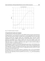
4.2 Motor control
Two drive motors contribute effort for the tracking motion of the robot. As the tracking rails
are not always straight, the speeds of the two motors are not the same when the robot is
moving. The torque control together with a position feedback algorithm is implemented.
Fig. 8 shows the control principle.
Fig. 8 Tracking motor control
Parallel Manipulators, Towards New Applications
372
In this method, one motor works as master, and another one works as slave. For the master
motor, the position control plus the speed control is applied to guarantee the required speed
and position accuracy of the carriage on the tracking rail. For the slave motor, the torque
control is applied, which contributes the driving torque for the robot.
4.3 Control of hardware and software
Because there are no commercial controller and software available for the special functions
of the parallel robot, an open architecture of hardware and programmable software are
being developed. Fig. 9 shows the structure of hardware control system. The controller is an
industrial-PC-based motion controller. It provides a reliable and easy-at-use environment
for controlling the robot because Earthnet bus is used in the connection of iPC and I/O
interfaces.
Fig.9 Structure of robot controller
The software is defined in Fig.10, including graphical interface, trajectory planning, forward
and inverse kinematics models, interpolator, controller, and I/O interface functions. And
Hybrid Parallel Robot for the Assembling of ITER
373
those functions have to be integrated with the program offered by iPC and run completely
in real time.
Graphical interface is a high level program, it includes parameter setting, condition
monitoring, and graphical visualization functions. User can easily exchange information
with this program.
Trajectory planning is also a high level program. As the robot has redundant actuators, the
trajectory planning is much more difficult than usual, so an optimization algorithm, which
is subjected to minimize the deflection of the robot during motion, has been employed.
Forward and inverse kinematics models and interpolator are real time functions, which generate
data for motion controller.
Controller is a real time function including water hydraulic controller and motor controller.
As the robot has two tracking motors and the speed of the motors are not always the same at
some positions, a master–slave control algorithm has been used.
I/O interface functions are real time functions, which enable transferring date from sensor to
controller and from controller to driver.
Fig. 10 Structure of software
5. Machining and welding testing mock-up
The parallel robot has been built in Lappeenranta University of Technology and the
machining and welding test mock-up is designed shown in Fig.11. The mock-up is one
Parallel Manipulators, Towards New Applications
374
quarter of a sector built up for testing the machining and welding functions of the robot.
Before the mock-up, some welding and machining tests have been carried out with the first
prototype of the parallel robot named Penta-WH. The laser welding with seam tracker has
been tested in stainless steel and the machine cutting with disc saw has been tested in the
stainless steel machining process. The robot performs well in the tests.
5.1 Machining
The cutting test was carried out with stainless steel. The high speed steel cutting tool was
used in the test. It is 200mm in diameter and 4mm in thickness. The problem in the
experiment was that the high speed cutting tool wore out quickly during the cutting. The
carbide tools, which are much more suitable for cutting stainless steel, are suggested to be
used in the cutting operations in the ITER.
Fig.11 VVPSM mock-up and final version of parallel robot
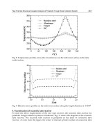
5.2 Laser welding test
In the ITER assembly, the high quality welds are required to avoid the leak of tritium. They
can be achieved by a highly automatic and remotely controlled welding procedure. To
guarantee the welding quality, a seam tracker, which guides the robot motions along the
center of a welding seam, is employed. With a seam tracker, the parallel robot has the
capability to correct the motion trajectory on-line to keep the welding head at the right
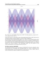
position and orientation in relation to the welding seam. The position errors of the welding
head related to the welding seam caused by the distortion of material and the imprecise
track rail are described in Fig.12.
Hybrid Parallel Robot for the Assembling of ITER
375
During testing, the laser welding head is mounted on the end-effector of the parallel robot
while the seam tracking sensor is mounted in the front of the welding head for guiding the
robot welding (Fig.12). The work piece is assembled randomly in the y and z directions
during testing. It has approximately a one-degree angle about the Y and Z-axes. The
position of seam is unknown for the robot before the seam finding. The maximum output
power used in the testing is 3 kW YAG. It has a 200mm focal length resulting in a 0.6 mm
diameter focal spot on the work piece. The beam parameter product is 25 mm-mrad. The
work piece is made of stainless steel AISI 316LN. It has a 7mm-thickness, 600mm-length,
and 0.2mm-root gap for welding.
Fig.12 Principle of seam tracker
Two seam tracking algorithms were tested during laser welding trials. One is the off-line
teaching algorithm that has two steps: (i) the robot follows the planned trajectory of the
seam and records the data from the seam tracker; and after that (ii) the robot compensates
the motion trajectory from the data recorded and starts welding following the new motion
trajectory. Fig.13 shows the welding results. The second algorithm is the on-line teaching
algorithm. In the algorithm, the robot corrects the trajectory on-line using data from the
seam tracker during the welding motion. Fig.14 shows the welding results achieved during
the tests.From the test results, we can conclude that the on-line teaching algorithm is better
than the off-line teaching algorithm, because the on-line teaching algorithm compensates the
distortion of the work piece during the welding process.
Parallel Manipulators, Towards New Applications
376
Fig.13 Off-line teaching welding results
Fig.14 On-line tracking welding results
Hybrid Parallel Robot for the Assembling of ITER
377
6. Conclusion
A hybrid parallel robot with four additional serial motion axes is developed for carrying out
the necessary machining and welding tasks in the assembling and repairing of the ITER
Vacuum Vessel. The robot is capable of holding all necessary machining tools and welding
end-effectors in all positions accurately and stably. The kinematics analysis of the robot is
presented. The models are complex because of the redundant structure of the robot. The
models are separately derived for the Hexa-WH and the carriage mechanism. An
optimization algorithm finds the solution in the trajectory planning, ensuring the maximum
stiffness during the robot motion. The experiments of the laser welding tests with the seam
tracker have been carried out. Both the on-line and off-line teaching algorithms have been
developed and the results show that the online teaching algorithm is better. The machining
cutting tests with stainless steel have been tested. The entire design and testing process of
the robot is a very complex task due to the high specialization of the manufacturing
technology needed in the ITER reactor. The results demonstrate the applicability of the
proposed solutions quite well.
7. Acknowledgement
The laser welding test is carried out in collaboration with the laser laboratory of VTT in
Lappeenranta, Finland, the whole work, supported by the European communities under the
contract of Association between EURATOM/Finnish TEKES, was carried out within the
framework of the European Fusion Development Agreement, and the views and opinions
expressed herein do not necessarily reflect those of the European Commission.
8. References
D. Stewart (1965), A platform with six degree of freedom, Proc. Inst. Mech. Eng., London,
Vol. 180, pp. 371-386.
T. C. Arai, K. Homma, H. Adachi, and Nakamura (1991), Development of parallel link
manipulator for underground excavation task, Proc. Int. Symposium on Advanced
Robot Technology, pp. 541-548.
C. Gosselin and J. Hamel (1994), The agile eye: A high-performance three degree of freedom
camera –orienting device, Proc. IEEE Int. Conference on Robotics and Automation,
pp. 781-786.
L. W. Tsai (1999), Robot analysis: The mechanics of serial and parallel manipulators, A
Wiley-Interscience Publication, John Wiley & Sons Inc.
G. Lebret, K. Liu, and L. Lewis (1993), Dynamic analysis and control of a Stewart platform
manipulator, J. Robotic Systems, Vol. 5, No. 10, pp. 629-655.
G. Zheng, L. S. Haynes, J. D. Lee and R. Carroll(1992), On the dynamic model and kinematic
analysis of a class of Stewart platforms, Robotics and Autonomous Systems, Vol. 9,
pp. 237- 254.
K. H. Häfele, H. Haffner, and P. Spencer (1992), “Automatic Fettling Cell- An Example for
Applying Computer- Aided Robotics”, Industrial Robot. Vol.19 No. 5. pp.31-34