Báo cáo hóa học: "Synthesis and Growth Mechanism of Ni Nanotubes and Nanowires" potx
Bạn đang xem bản rút gọn của tài liệu. Xem và tải ngay bản đầy đủ của tài liệu tại đây (530.55 KB, 6 trang )
NANO EXPRESS
Synthesis and Growth Mechanism of Ni Nanotubes and Nanowires
Xiaoru Li Æ Yiqian Wang Æ Guojun Song Æ Zhi Peng Æ
Yongming Yu Æ Xilin She Æ Jianjiang Li
Received: 23 December 2008 / Accepted: 14 May 2009 / Published online: 31 May 2009
Ó to the authors 2009
Abstract Highly ordered Ni nanotube and nanowire
arrays were fabricated via electrodeposition. The Ni
microstructures and the process of the formation were
investigated using conventional and high-resolution trans-
mission electron microscope. Herein, we demonstrated the
systematic fabrication of Ni nanotube and nanowire arrays
and proposed an original growth mechanism. With the
different deposition time, nanotubes or nanowires can be
obtained. Tubular nanostructures can be obtained at short
time, while nanowires take longer time to form. This for-
mation mechanism is applicable to design and synthesize
other metal nanostructures and even compound nanostuc-
tures via template-based electrodeposition.
Keywords Nanotubes Á Nanowires Á Growth mechanism Á
Electrodeposition
Introduction
Nanostructures have received comprehensive attention
owing to their novel optical, electrical, catalytic and
magnetic properties and their potential applications in
nanoscale electronic, sensing, mechanical and magnetic
devices [1, 2], and information storage systems [3–6].
Among various synthetic processes, template synthesis has
been proved to be a versatile and simple approach for the
preparation of many nanostructures, such as conductive
polymers, metals, semiconductors, carbon and other
materials [7–10]. Among these materials, metal nano-
structures have been the focus of extensive research
activities due to their unusual properties [11]. Many groups
have focused on the magnetic properties of nickel (Ni)
nanotubes and/or nanowires [12–15], because of their small
magnetocrystalline anisotropy energy and potential appli-
cation in devices. Some groups have studied the formation
mechanism of the Ni nanostructures [16–21], but the
growth mechanism is still unclear so far. Therefore, a
complete understanding of the growth mechanism needs
intense investigation. This has aroused our interest to
explore the growth mechanism of Ni nanotubes and
nanowires.
In our work, we not only report the successful fabrica-
tion of ordered Ni nanotube and nanowire arrays using
anodic aluminum oxide (AAO) templates by changing
electrodeposition conditions, but also propose a growth
mechanism for Ni nanotubes and nanowires. The proposed
growth mechanism for Ni nanotubes and nanowires in our
work is different from others reported before and is easier
for the readers to understand. The obtained Ni nanotubes
are more likely to enable us to fix metals or semiconductors
in order to achieve novel nanocomposites with unique
physical properties, and the Ni nanowire arrays might have
potential applications in the magnetic–electric devices.
Experimental Section
Nanotubes and nanowires were synthesized using template-
directed electrochemical deposition, an approach pioneered
X. Li Á G. Song (&) Á Z. Peng Á Y. Yu Á X. She Á J. Li
Institute of Polymer Materials, Qingdao University, No. 308
Ningxia Road, Qingdao 266071, China
e-mail:
Y. Wang
Laboratory of Advanced Fiber Materials and Modern Textile,
The Growing Base for State Key Laboratory, Qingdao
University, No. 308 Ningxia Road, Qingdao 266071,
People’s Republic of China
123
Nanoscale Res Lett (2009) 4:1015–1020
DOI 10.1007/s11671-009-9348-0
by Martin [7, 8]. In general, AAO films are formed by the
electrochemical oxidation of aluminum. Depending on the
type of anodization process and growth regime used, alu-
minum oxide membranes can be fabricated to contain
nanopores with a wide range of diameters, lengths and
interpore distances. To facilitate nanowire fabrication,
commercially available aluminum oxide membranes,
Whatman Anodisc 25, were used, with a nominal pore
diameter ranging from 150 to 300 nm and depths ranging
from 50 to 60 lm.
The side of the AAO membrane was sputtered with a
layer of Au as a work electrode. In a tri-electrode elec-
trochemical system, the Ni nanostructure arrays were
produced in the template pores from a solution of 0.8 mol/
L NiSO
4
Á6H
2
O ? 0.5 mol/L H
3
BO
3
? 0.3 mol/L KCl by
direct current electrodeposition. The electrodeposition was
carried out using platinum as an anode and a calomel
electrode as a reference electrode. Finally, the nanowire
arrays were revealed by the removal of AAO in a 3 mol/L
sodium hydroxide solution. Three samples were prepared
under different electrodeposition conditions. They were
labeled as sample 1 (applied voltage: -0.8 V, deposition
time: 20 min, corresponding current: 0.03–0.11 mA),
sample 2 (-0.8 V, 40 min, 0.03–0.19 mA) and sample 3
(-0.8 V, 60 min, 0.04–0.26 mA).
The morphology of the Ni nanostructure arrays was
investigated using a JEOL JSM-6390LV SEM. The struc-
ture and microstructure of the Ni nanotubes and nanowires
were investigated using a JEOL JEM-2000EX TEM. The
specimen for TEM observation was prepared by evapo-
rating a drop (5 lL) of the nanostructure dispersion onto a
carbon-film-coated copper grid. The growth process of Ni
nanotubes and nanowires was investigated using high-res-
olution transmission electron microscope (HRTEM).
Results and Discussion
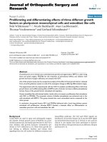
With different deposition time, Fig. 1a–f show clearly the
top-view and side-view images of Ni nanostructures with
different deposition time. Figure 1a shows a typical SEM
image of highly ordered nanotube arrays with a deposition
time of 20 min obtained after the removal of AAO in
aqueous NaOH, illustrating clear open ends. As deposition
time increases, nanowires were formed. Figure 1c and e
show the morphologies of nanowires formed after a
deposition time of 40 and 60 min respectively. From
Fig. 1c, e, the top views of the nanowires, it can be clearly
seen that the Ni nanowires have solid ends. The length of
the Ni nanostructures increases with the electrodeposition
times. Figure 1b, d, f present side views of Ni nanotubes
and nanowires corresponding to Fig. 1a, c, e, respectively.
It is clear that the length of the Ni nanowires shown in
Fig. 1f is the longest, about 20 lm, and in Fig. 1b is the
shortest, about 3 lm.
It can be seen from Fig. 1 that there is a length distri-
bution for the nanotubes and nanowires in each sample.
This is due to the difference of barrier layer thickness at
each pore and also due to the hydrogen evolution caused by
water-splitting reaction [22]. Ni
2?
ions are reduced during
the electrodeposition by the electrons tunneled through the
barrier layer. However, the barrier layer at each pore could
be branched differently during the thinning process of the
barrier layer, resulting in different energy barriers for
tunneling because of different barrier layer thickness [23].
The number of tunneled electrons through an insulating
layer decreases exponentially with the thickness of the
insulating layer according to Bethe’s equation [24]. Con-
sequently, the rate of deposition becomes different at each
pore.
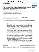
The formation process of Ni nanowires was investi-
gated using TEM. Figure 2 presents typical TEM images
of these three samples. Figure 2a shows that some
nanostructures have a characteristic of half wire and half
tube. It is believed that the wire end is the starting point.
As time increases, Ni nanotubes and nanowires coexist in
the same template under the same experimental condi-
tions, as shown in Fig. 2b. Figure 2c shows that whereas
most nanostructures are Ni nanowires, a small amount of
nanostructures is nanotubes. It can be seen from Fig. 2c
that nanowires are not very uniform: one end is a little
thicker than the other end, and some nanowires have
branches. It depends on the quality of the commercial
AAO templates, as shown in the SEM image of AAO
pores (Fig. 2d).
From the TEM results, we conclude that the formation
process of Ni nanowires begins with the formation of Ni
nanotubes. Nanotubes were formed at first, and then Ni
nanoparticles of the electrode stacked randomly in the
tubes, until nanowires were formed. The formation pro-
cess is revealed vividly in Fig. 2a. With the increase in
deposition time, nanotubes disappear gradually, and the
amount of nanowires increases further. However, nano-
tubes still exist despite of the increased deposition time,
because Ni
2?
ions concentration in the margin region of
the templates is low and can not be supplemented from
the whole solution in time. So, Ni nanoparticles are not
enough to fill the Ni nanotubes in time; therefore, Ni
nanotubes still exist in the margin regions of the
templates.
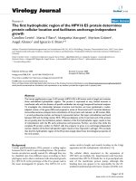
The formation process of the Ni nanostructures was
further investigated using HRTEM. Figure 3a shows that
a small amount of nanoparticles is randomly arranged in
the inner surface of the Ni nanotubes. However, the
amount of nanoparticles increases with the deposition
time. It can be seen clearly that nanoparticles (in Fig. 3b)
1016 Nanoscale Res Lett (2009) 4:1015–1020
123
are much more than those in Fig. 3a. A certain amount of
Ni nanoparticles joined together to form Ni nanotubes. As
the deposition time increases, more and more Ni nano-
particles join together to form a wire, as can be seen in
Fig. 3c. From Fig. 3c, it can be seen that the nanowire is
formed by many nanograins with different crystallo-
graphic orientations.
Based on our experimental results, deposition time is a
critical condition to produce nanotubes or nanowires.
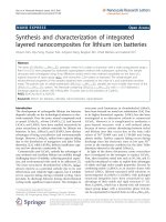
However, applied current density (E field) affected the
formation of nanotubes and nanowires. Figure 4 illustrates
schematic diagrams of the electrodeposition process for Ni
nanotubes and nanowires. Figure 4a provides a clear
understanding of the growth mechanism of Ni nanotubes.
The junction between the electrode surface and the bottom
edge of the template pore serves as a preferential site for
the deposition of metal ions, because the inner walls of the
nanochannels have surface absorption energy [25, 26]. At
the beginning, Ni ions move toward the electrode and
receive electrons to become atoms. A certain amount of
atoms can aggregate together to form Ni nanoparticles,
which are absorbed onto the surface of the inner walls of
the nanochannels. When the surface absorption energy is
stronger than the E field, Ni nanoparticles will be prefer-
entially distributed on the surface of the inner walls of the
nanochannels, and tubular nanostructures are obtained as
mentioned earlier.
Figure 4b shows vividly the formation process of the
nanowires. When Ni nanotubes are formed, the surface
absorption energy of nanochannels decreases accordingly.
When the E field is preferential, Ni nanoparticles begin to
stack inside the tubes from the electrode surface until the
nanotubes are completely filled, and nanowires are
obtained.
Fig. 1 Typical SEM images of
Ni nanotube and nanowire
arrays obtained under different
conditions: (a), (c) and (e) are
top views of samples 1, 2 and 3
respectively; (b), (d) and (f) are
side views of the samples 1, 2
and 3 respectively
Nanoscale Res Lett (2009) 4:1015–1020 1017
123
In summary, nanoparticles stack inside the tubes to form
nanowires when the E field reached a certain value. We
have termed this growth mechanism brick-stacked wirelike
growth (BSWG). Cao et al. [20] have proposed a current-
directed tubular growth (CDTG) mechanism. They
believed that metal nanotubes can be obtained at v
k
(growth
rate parallel to current direction) » v
\
(growth rate per-
pendicular to current direction), while nanowires can be
obtained at v
k
& v
\.
. However, we think that it is difficult
to define the competitive rates.
It is well known that Ni is a magnetic material with very
small magnetocrystalline anisotropy energy [12]. The
crystallographic orientations of these nanoparticles are
different, so the shape anisotropy of these nanoparticles is
also different. The adjacent nanoparticles will repel each
other, resulting in Ni nanoparticles being randomly arran-
ged and the grains having different crystallographic ori-
entations, as shown in Fig. 3c.
Our results fully demonstrate that magnetic materials
can form nanotubes and nanowires under appropriate
synthesis conditions. We believe that the BSWG
mechanism can be applied to synthesize other magnetic
metal nanostructures. Controlling the synthesis conditions,
other metal nanostructures can be deposited in magnetic
nanotubes to form novel nanocomposite materials.
Conclusion
In summary, highly ordered Ni nanotubes and nanowires
have been fabricated by DC electrodeposition in the pores
of AAO templates under the deposition voltage of -
0.8 V. Ni nanotubes were obtained when the deposition
time was less than 20 min, and the corresponding current
was 0.03–0.11 mA, while Ni nanowire arrays were
obtained when the deposition time was more than 40 min
and when the current was more than 0.19 mA. Systematic
HRTEM investigations demonstrate the formation process
of Ni nanostructures, and the growth mechanism for Ni
nanotubes and nanowires has also been explored. We
believe that the BSWG mechanism can be applied for
other magnetic nanostructures; especially, such metal
Fig. 2 TEM images of Ni
nanowires and nanotubes: (a)
sample 1, (b) sample 2, (c)
sample 3 and (d) SEM image of
AAO pores
1018 Nanoscale Res Lett (2009) 4:1015–1020
123
nanotubes with open ends have a variety of promising
applications, such as porous electrodes filled with ferro-
magnetic and nonmagnetic metals to fabricate magnetic
multilayer nanostructure, or other materials to prepare
novel nanocomposite materials with special magnetic,
optical or electrical properties.
Fig. 3 HRTEM images of Ni
nanowires and nanotubes for
samples under different
conditions: (a) sample 1, (b)
sample 2 and (c) sample 3
Fig. 4 a Schematic diagram of
the growth process of
nanotubes; b Schematic
diagram of the growth process
of nanowires (the white and
black balls showing different
crystallographic orientations)
Nanoscale Res Lett (2009) 4:1015–1020 1019
123
Acknowledgments This work was financially supported by the
National Natural Science Foundation of China (No. 50473012) and
the Provincial Natural Science Foundation (No. Z2005F03).
References
1. N.I. Kovtyukhova, T.E. Mallouk, Chem. Eur. J. 8, 4354 (2002).
doi:10.1002/1521-3765(20021004)8:19\4354::AID-CHEM4354
[3.0.CO;2-1
2. F. Patolsky, G. Zheng, O. Hayden, M. Lakadamyali, X. Zhuang,
C.M. Lieber, Proc. Natl. Acad. Sci. U.S.A. 104, 14017 (2004).
doi:10.1073/pnas.0406159101
3. M.S. Gudiksen, L.J. Lauhon, J.F. Wang, D.C. Smith, C.M. Lie-
ber, Nature 415, 617 (2002). doi:10.1038/415617a
4. Y. Cui, Q.Q. Wei, H.K. Park, C.M. Lieber, Science 293, 1289
(2001). doi:10.1126/science.1062711
5. T. Thurn-Albrecht, J. Schotter, C.A. Ka
¨
stle, N. Emley, T. Shi-
bauchi, L. Krusin-Elbaum, K. Guarini, C.T. Black, M.T. Tu-
ominen, T.P. Russell, Science 290, 2126 (2000). doi:10.1126/
science.290.5499.2126
6. H.P. Liang, Y.Q. Guo, J.S. Hu, C.F. Zhu, L.J. Wan, C.L. Bai,
Inorg. Chem. 44, 3013 (2005). doi:10.1021/ic0500917
7. C.R. Martin, Science 266, 1961 (1994). doi:10.1126/science.266.
5193.1961
8. C.R. Martin, Chem. Mater. 8, 1739 (1996). doi:10.1021/cm960
166s
9. A. Huczko, Appl. Phys. A 70, 365 (2000). doi:10.1007/s00339
0051050
10. K. Peng, Z. Huang, J. Zhu, Adv. Mater. 16, 73 (2004). doi:
10.1002/adma.200306185
11. K.R. Pirota, D. Navas, M. Hernandez-Velez, K. Nielsch, M.
Vazquez, J. Alloy Compd. 369, 18 (2004). doi:10.1016/j.jallcom.
2003.09.040
12. F. Tian, J. Zhu, D. Wei, J. Phys. Chem. C 111, 12669 (2007). doi:
10.1021/jp0737294
13. M. Hangarter Carlos, V. Myung Nosang, Chem. Mater. 17, 1320
(2005). doi:10.1021/cm047955r
14. M.A. Mousa, J. Imran, Alloys Compd. 455, 17 (2008). doi:
10.1016/j.jallcom.2007.01.051
15. J.B. Shi, Y.C. Chen, C.W. Lee, Y.T. Lin, C. Wu, C. Chen, J.
Mater. Lett. 62, 15 (2008). doi:10.1016/j.matlet.2007.04.060
16. H. Pan, B.H. Liu, J.B. Yi, C. Poh, S.H. Lim, J. Ding, Y.P. Feng,
C.H.A. Huan, J.Y. Lin, J. Phys. Chem. B 109, 3094 (2005). doi:
10.1021/jp0451997
17. C.G. Jin, W.F. Liu, C. Jia, X.Q. Xiang, W.L. Cai, L.Z. Yao, X.G.
Li, J. Cryst. Growth 258, 337 (2003). doi:10.1016/S0022-
0248(03)01542-2
18. D.J. Sellmyer, M. Zheng, R. Skomski, J. Phys.: Condens. Matter
13, R433 (2001)
19. F. Tian, J. Chen, J. Zhu, J. Apply, Phys 103, 013901 (2008)
20. H.Q. Cao, L.D. Wang, Y. Qiu, Q.Z. Wu, G.Z. Wang, L. Zhang,
X.W. Liu, ChemPhysChem 7
, 1500 (2006). doi:
10.1002/cphc.200500690
21. Q.T. Wang, G.Z. Wang, X.H. Han, X.P. Wang, J.G. Hou, J. Phys.
Chem. B 109, 23326 (2005). doi:10.1021/jp0530202
22. S.K. Hwang, S.H. Jeong, O.J. Lee, K.H. Lee, Microelectron. Eng.
77, 2 (2005). doi:10.1016/j.mee.2004.07.069
23. Y.C. Sui, B.Z. Cui, L. Martı
0
nez, R. Perez, D.J. Sellmyer, Thin
Solid Films 406, 64 (2002). doi:10.1016/S0040-6090(01)01769-2
24. E.E. Polymeropoulos, J. Appl. Phys. 48, 2404 (1977). doi:
10.1063/1.324002
25. M. Lahav, T. Sehayek, A. Vaskevich, I. Rubinstein, Angew.
Chem. 115, 5734 (2003). doi:10.1002/ange.200352216
26. M. Lahav, T. Sehayek, A. Vaskevich, I. Rubinstein, Angew.
Chem. Int. Ed. Engl. 42, 5576 (2003). doi:10.1002/anie.2003
52216
1020 Nanoscale Res Lett (2009) 4:1015–1020
123