Báo cáo hóa học: "Research Article Minimizing Detection Probability Routing in Ad Hoc Networks Using Directional Antennas" pptx
Bạn đang xem bản rút gọn của tài liệu. Xem và tải ngay bản đầy đủ của tài liệu tại đây (821.61 KB, 8 trang )
Hindawi Publishing Corporation
EURASIP Journal on Wireless Communications and Networking
Volume 2009, Article ID 256714, 8 pages
doi:10.1155/2009/256714
Research Article
Minimizing Dete ction Probability Routing in
Ad Hoc Networks Using Directional Antennas
Xiaofeng Lu,
1
Don Towsley,
2
Pietro Lio’,
3
Fletcher Wicker,
4
and Zhang Xiong
1
1
School of Computer Science, Beijing University of Aeronautics and Astronautics, Beijing 100191, China
2
Department of Computer Science, University of Massachusetts at Amherst, Amherst, MA 01003-9264, USA
3
Computer Laboratory, University of Cambridge, Cambridge CB3 0FD, UK
4
Communication Network Architectures Subdivision, The Aerospace Corporation, CA 90245-4691, USA
Correspondence should be addressed to Xiaofeng Lu,
Received 31 January 2009; Revised 1 April 2009; Accepted 3 May 2009
Recommended by Shuhui Yang
In a hostile environment, it is important for a transmitter to make its wireless transmission invisible to adversaries because an
adversary can detect thetransmitter if the received power at its antennas is strong enough. This paper defines a detection probability
model to compute the level of a transmitter being detected by a detection system at arbitrary location around the transmitter. Our
study proves that the probability of detecting a directional antenna is much lower than that of detecting an omnidirectional antenna
if both the directional and omnidirectional antennas provide the same Effective Isotropic Radiated Power (EIRP) in the direction
of the receiver. We propose a Minimizing Detection Probability (MinDP) routing algorithm to find a secure routing path in ad hoc
networks where nodes employ directional antennas to transmit data to decrease the probability of being detected by adversaries.
Our study shows that the MinDP routing algorithm can reduce the total detection probability of deliveries from the source to the
destination by over 74%.
Copyright © 2009 Xiaofeng Lu et al. This is an open access article distributed under the Creative Commons Attribution License,
which permits unrestricted use, distribution, and reproduction in any medium, provided the original work is properly cited.
1. Introduction
In a wireless network, nodes communicate with others
through shared wireless medium, which makes the com-
munications more susceptible to passive eavesdropping and
malicious trafficanalysis[1]. An adversary may eavesdrop
network in order to discover the location of the transmitter.
These adversaries are referred as detection systems. If the
power received by a detection system is strong enough, the
detection system can distinguish the transmission signals
from the electromagnetic noise, and it becomes aware of the
existence of a transmitter. If more than two detection systems
detect a transmitter in a synchronous manner, they are
able to compute the transmitter’s position with localization
algorithms and go to find the transmitter and catch it.
Hence, transmission with low detection probability is very
important in an untrustworthy network.
Typically, the assumption for ad hoc networks is that
nodes are equipped with omnidirectional antennas, which
can transmit and receive signals in all horizontal directions
[2, 3]. However, a directional antenna can get antenna gain
in the main lobe direction, thus transmitters can use the
directional antenna to transmit signals farther away than
omnidirectional antennas with the same transmit power, or
transmit signals to a receiver while using less transmit power
[2, 4].
Theworkin[5–8] mentioned that directional antennas
can reduce the detection probability, but no study has
been conducted to compare the detection probability of
directional and omnidirectional antennas. On the other
hand, using directional antennas to achieve secure routing
has not been studied yet.
Researchers in the past have done much fundamental
research on directional antennas in wireless networks that
focused on medium-access control, spatial reuse, efficient
power consumption, network capacity, and so forth. The
work in [9–13] proposed adaptive Medium-Access Control
(MAC) protocols to improve IEEE 802.11. These adaptive
MAC protocols attempted to limit the disadvantages of IEEE
802.11 in spatial use. Power is another constrained source
2 EURASIP Journal on Wireless Communications and Networking
Antenna
(a)
Antenna
(b)
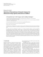
Figure 1: Transmission region of omnidirectional antenna and
directional antenna.
in some ad hoc network scenarios because in these cases
the power for the antenna comes from batteries, which
are energy-constrained. Sometimes, nodes equipped with
batteries-powered antennas cannot recharge frequently. This
is another reason for using directional antennas. Authors
of [14, 15] described the advantages of using directional
antennas to reduce power consumption in ad hoc networks.
As directional antennas can increase spatial use [16], more
than one directional antenna can send data at the same time.
Directional antennas can also increase network capacity [17,
18].
In this paper, we address the work we have done on
routing path selection to reduce the transmitter’s probability
of being detected by adversaries in ad hoc networks. This
paper is organized as follows. Section 2 introduces the
antenna model. We introduce the detection probability
model in Section 3 and our minimizing detection probability
routing algorithm in Section 4.InSection 5,wereviewsome
related work about anonymous routing and secure routing
protocols. Finally, we conclude our work in Section 6.
2. Antenna Model
Antennas are either omnidirectional mode or directional
mode [2, 3]. Omnidirectional antennas cover 360 degrees
and send data in all directions. All nodes in the radia-
tion region can receive the communication signals [2, 3].
Omnidirectional antennas spread the electromagnetic energy
over a large region, while only small portion is received by
the desired receivers, so the omnidirectional transmissions
waste a large portion of the transmit power and the network
capacity.
Directional transmission can overcome this disadvan-
tage. A directional antenna can form a directional beam
pointing at the receiver by concentrating its transmit power
into that direction. By pointing the main lobe at the
receiver, a directional antenna can get more antenna gain in
the direction of the receiver. Directional antennas strongly
reduce signal interference in unnecessary directions.
In our antenna model, we assume that an antenna can
work in two modes: omnidirectional mode and directional
mode. It can send and receive data in both these two modes
[2]. If nodes have nothing to transmit, their antennas work
in omnidirectional mode to detect signals. A receiver and a
transmitter can communicate over a larger distance when
both antennas are in directional mode than just one of them
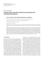
100806040200−20−40−60−80−100
Angleofboresite(degrees)
−25
−20
−15
−10
−5
0
5
10
15
20
25
Gain (dB)
Figure 2: A directional antenna gain function.
is in directional mode while another is in omnidirectional
mode.
Effective Isotropic Radiated Power (EIRP) is the gain of a
transmitting antenna multiplied by the net power accepted
by the antenna from the connected transmitter in a given
direction [19]. As the gain and received power are measured
in dB, EIRP can be calculated as
EIRP
= P
t
+ G
t
,(1)
where P
t
is the transmit power in dBW, and G
t
is the antenna
gain in dBi (dB
= 10 log
10
(x)).
Antenna gain refers to an antenna’s ability to direct its
radiated power in a desired direction, or to receive energy
preferentially from a desired direction [4]. It is defined as
the ratio of the radiation intensity of an antenna in a given
direction to the intensity of the same antenna as it radiates in
all directions (isotropically) and has no losses [20]. Antenna
gain is expressed in dBi.
For an omnidirectional antenna, because the ratio of the
radiation intensity is 1, the antenna gain is 10 log
10
(1) = 0. As
a directional antenna concentrates the transmit power into
the main lobe direction, the radiation intensity in the main
lobe direction is larger than that in other directions and its
G
t
in that direction is much larger than zero. Therefore, the
directional antenna can provide the same EIRP in the main
lobe direction as that an omnidirectional antenna provides
while using much less transmit power than that the omni-
direction antennas uses.
No directional antenna is able to radiate all of its energy
in one preferred direction. Some is inevitably radiated in
other directions. These smaller peaks in Figure 1(b) are
referred to as side lobes, commonly specified in dBi down
from the main lobe. Figure 2 shows a case directional
antenna gain in main lobe, side lobes, and back lobe.
As different antennas have different antenna structures
and physical characteristic, their antenna gain functions are
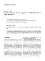
different. We use an approximate gain function to fit the
directional antenna gain function. This approximate gain
function is showed in Figure 3.
EURASIP Journal on Wireless Communications and Networking 3
100806040200−20−40−60−80−100
Angleofboresite(degrees)
−25
−20
−15
−10
−5
0
5
10
15
20
25
Gain (dB)
Figure 3: An approximate directional antenna gain function.
3. Detection Probability Model
3.1. Link Budget Equation. If the power received by a
detection system is strong enough, the detection system can
distinguish the transmission signals from electromagnetic
noise. The ratio of the total received signal power to the total
noise which includes thermal and system noise plus total
interference is denoted as SNIR [21]. Hence, the detection
event occurs if and only if the SNIR is larger than a threshold
λ at a detection system.
The equation to compute the total received signal level at
the receiver antenna is the following [22]:
S
= P
t
+ G
t
+ G
r
− C
t
− C
r
−
Pl,(2)
where P
t
(dBW) is the transmitter’s power level, G
t
(dBi)
is the transmitter’s antenna gain in the direction towards
the receiver, G
r
(dBi) is the receiver’s antenna gain in the
direction of the transmitter, C
t
is the transmitter’s cable
attenuation, C
r
is the receiver’s cable attenuation, and
Pl
is adaptive transmission path loss, which we will discuss
carefully later. C
t
and C
r
are assumed to be zero here.
The total noise level at the receiving unit is
N
= k +dB
(
T
r
+ T
e
)
+dB
(
BW
)
+ I (3)
where k is Boltzmann constant equal to
−228.6 dB(Watts/
(Hertz
∗ Degree Kelvin)). T
r
is noise temperature at the
receiver’s antenna and T
e
is environment noise temperature
at the receiver’s antenna [22]. The receiving bandwidth is of
course matched to communication signal’s bandwidth BW.
The final term I is the total interference power level. The
impact of interference is assumed to be zero in our study.
Free-space path loss (FSPL) is the loss in signal strength
of an electromagnetic wave that would result from a line of
sight path through free space, with no obstacles nearby to
cause reflection or diffraction [23]. This loss is calculated
using the following formula:
pl
d, f , n
=
c +20log
10
(
d
)
+20log
10
f
,(4)
where d is the distance from the transmitter to the receiver,
the radio frequency is f ,andc is a constant that depends of
the units of measure for d and f . With the units of measure
for d and f listed in Table 1 , c
=−27.55.
d
x
Detection
system
θ
Figure 4: Illustration of d and θ.
Past line of sight, communications is still possible, but
there is additional attenuation due to shadowing. Addition-
ally it is well know that the average receive power level,
measured in dBW, around a circle at a constant distance from
the transmitter and beyond the line of sight is a lognormally
distributed random variable. Let
Pl(d, f ,n) be the path loss
when the distance from the receiver to the transmitter is
larger than the line of sight distance. We modify the FSPL
formula and propose an adaptive path loss formula:
Pl
d, f , n
=−
27.55 + n10 log
10
(
d
)
+20log
10
f
,(5)
where n is determined by the terrain type.
In our analysis, the coefficient n is a random variable that
depends of the type of terrain, that is, how rugged the terrain
is to radio frequency waves. Typical terrain types include
open rural, rural trees and rolling hills, suburban, and urban.
For each of the terrain types there is an average distance to
the edge of the unobstructed line of sight given. Beyond this
limit, the value of n is drawn uniformly random between
the values listed in Ta ble 2 with the possibility that there are
locations that have direct line of sight beyond this average.
3.2. D etection Probability Model. Nowwestudytheissueof
the probability that a detection system detects a transmitter.
Let the direction of the directional antenna’s peak radiation
intensity lie on the positive x axis and the star node
be a detection system in Figure 4. The distance from the
transmitter to the detection system is d and the angle
between the direction of the detection system and the
direction of the positive x axis is θ.Wewillused and θ in
the following sections of this paper with the same meanings
defined here. We assume that the detection system’s antenna
works in omnidirectional mode.
Thedetectioneventoccursatadetectionsystemifand
only if the SNIR is larger than the threshold λ:
Pr(Detection)
= Pr(SNIR >λ),
SNIR
= S − N. (6)
Substitute (2), (3), and (5) into (6).
SNIR
= P
t
+ G
t
(
θ
)
+27.55
− n10 log
10
(
d
)
− 20 log
10
f
−
k − dB
(
T
r
+ T
e
)
− dB
(
BW
)
+ G
r
,
(7)
4 EURASIP Journal on Wireless Communications and Networking
Table 1: Variable definitions for link budget equations.
Symbol
Meaning
Value Units
P
t
Transmitter power level
–dBW
G
t
Transmit antenna gain in the direction of the hostile
antenna
Figure 3 dB
f
Radio frequency
2500 MHz
d
Distance between the transmitter and hostile node
Calculated M
G
r
Receiver antenna gain in the direction of the transmit
antenna
0dB
S
Total received signal level after receive antenna
Equation (2)dBW
BW
Hostile receiver’s Bandwidth
1000000 Hertz
T
r
Noise temperature of hostile antenna
500 Degrees Kelvin
T
e
Environment noise temperature at hostile antenna
300 Degrees Kelvin
T
Total system noise temperature at hostile antenna
T
r
+ T
e
Degrees Kelvin
N
Total noise level in signal bandwidth at hostile antenna
Equation (3) dB Watts
Table 2: Terrain type parameters.
Terrain type Distance to horizon (m)Rangeofn
Rural-open 1000 2 to 2.5
Rural-trees 300 2 to 4.0
Suburban 200 2 to 5.0
Urban 100 2 to 6.0
where G
t
(θ) is the transmitter’s antenna gain function as
Figure 3 shows, and G
r
= 0. As P
t
,20log
10
f ,dB(T
r
+ T
e
),
and dB(BW) are constants, let
K
= P
t
+ 256.15 − 20 log
10
f − dB
(
T
r
+ T
e
)
+dB
(
BW
)
. (8)
Substitute (8) into the definition of the SNIR, the
probability of the detection event occuring is
Pr
(
SNIR >λ
)
= Pr
K + G
t
(
θ
)
− n10 log
10
d>λ
= Pr
K + G
t
(
θ
)
− λ
10 log
10
d
>n
.
(9)
Now we discuss the value of n, for each of the terrain
types listed in Table 1, there is an average distance to the edge
of the unobstructed line of sight given, which we defined as
d
0
. When the distance d is smaller than d
0
,wesetn equal to 2.
If the distance to the transmitter is greater than d
0
, the value
of n is a random variable between the values listed in Ta ble 1 :
Pr
(
SNIR >λ
)
= f
(
d, θ
)
=
⎧
⎪
⎪
⎪
⎪
⎨
⎪
⎪
⎪
⎪
⎩
K + G
t
(
θ
)
− λ
10 log
10
d
> 2, d
≤ d
0
,
K + G
t
(
θ
)
− λ
10 log
10
d
>n, d>d
0
,
(10)
where K is given by (8).
3.3. Model Analysis. Assume both the directional and omni-
directional antennas provide the same EIRP in the direction
100908070605040302010
X axis (Km)
100
90
80
70
60
50
40
30
20
10
Y axis (Km)
0.1
0.2
0.3
0.4
0.5
0.6
0.7
0.8
0.9
Figure 5: An omnidirectional antenna’s detection probability map.
of the receiver. Assume that the omnidirectional antenna’s
transmit power is 3 watt and the directional antenna’s gain
function is as Figure 3 shows, so the directional antenna’s
transmit power is 0.03 watt. We assume that the operational
area Ω is a finite area 100 kilometers
× 100 kilometers and the
terrain is rural-open. We place the transmitter at the center
of the operational area.
Figure 5 shows the detection probability map of an
omnidirectional antenna in the operational area. In this
figure, different colors mean different probability values. As
omnidirectional antennas radiate signals in all directions
equally, the contour lines are almost circles in Figure 5.
The detection probability becomes lower and lower with
the increase of the distance d. Figure 6 shows the detection
probability map of a directional antenna. Only locations
in the main lobe direction of the directional antenna have
high probabilities to detect the transmitter, the detection
probabilities at other directions are very low.
Let A
1
, , A
n
be a partition of the operational area Ω.
Assume that there is only one detection system that is in
EURASIP Journal on Wireless Communications and Networking 5
100908070605040302010
X axis (Km)
100
90
80
70
60
50
40
30
20
10
Y axis (Km)
0.1
0.2
0.3
0.4
0.5
0.6
0.7
0.8
0.9
Figure 6: A directional antenna’s detection probability map.
one of {A
i
}. According to the total probability theorem, the
probability of detecting the transmitter is
dp
= Pr
(
Detection
)
=
n
i=1
Pr
(
A
i
)
Pr
(
Detection
| A
i
)
, (11)
where Pr(A
i
) is the probability of the detection system being
in region A
i
. We assume that the probability of the detection
system being in A
i
are even, Pr(A
1
) = Pr(A
2
) = ··· =
Pr(A
n
). Then the probability of detecting the transmitter
is
dp
= Pr
(
Detection
)
=
n
i=1
Pr
(
Detection | A
i
)
n
. (12)
Here we assume that each A
i
is 1 km × 1km, which
is a small region for directional transmissions. Normally,
if two locations are very near, the detection probabilities
at these two locations should be almost equal, so we can
assume Pr(Detection
| A
i
) to be the detection probability
at the center of A
i
. Using equation (10), we can calculate
the probability of detecting a transmitter at the center of
A
i
.
The dp of Figure 5 is 0.36 and dp of Figure 6 is 0.012. This
indicates that directional antennas can reduce the detection
probability by over 96.7%. Comparing these two figures,
we can find that the area where the detection probability
being zero in Figure 6 is much larger than that in Figure 5
and the colorful area where the detection probabilities being
larger than 0.1 in Figure 6 is much less than that area in
Figure 5. This can explain why a directional antenna has
the lower detection probability than an omnidirectional
antenna if they provide the same EIRP in the direction of
receiver.
4. Minimizing Detection Probability
Routing Algorithm
4.1. Definition. We model adversaries as passive. Adversaries
in this model are assumed to be able to receive any transmit-
a
b
c
Antenna
(a)
a
b
c
(b)
Figure 7: An illustration of using directional antennas to bypass a
detection system.
ter’s signals but are not able to modify these signals. If a set
of adversaries detect a transmitter in a synchronous manner,
they may be able to compute the transmitter’s position
with localization algorithms. It is dangerous to reveal the
position information to adversaries, because adversaries
may find the transmitter and catch it according to its
position.
As directional antennas can transmit signals towards
a specific direction, we can employ several directional
antennasasrelaystobypassadetectionsystem.InFigure 7,
node a, b,andc are three network nodes and the black node
is a detection system. Assume that node a wants to send data
to node c.Ifnodea transmits data to node c directly using
directional antenna, as the detection system happens to lie
in main lobe direction of node a, it can detect node a with
100% probability. Or, node a cansenddatatonodec via
node b as Figure 7(b) shows. As the detection system is not
in the main lobe direction of these two directional antennas,
the probability of detecting the transmissions at the detection
system is very low as Figure 6 indicates.
Assume detection systems and network nodes are scat-
tered within the operational area. To make the relay trans-
mission from the source to the destination more secure, the
strategy of our routing algorithm is to Minimize Detection
Probability (MinDP) by selecting a routing path with the
lowest detection probability rather than the shortest distance
or the least power consumption. In Figure (8), the relay
transmission path (a
→ b → c → d → e)ismoresecure
than the path (a
→ b → c → e). If network nodes know
the locations of detection systems, they can use equation (10)
to calculate the detection probability. If network nodes do
not know the locations of detection systems, they can use
equation (12) to calculate the detection probability.
The goal of our routing protocol is to find a secure
routing path which has the lowest detection probability
throughout the whole delivery process from the source to
the destination. Assume that a packet would be delivered
from the source to the destination through N hops. If any
of these N hops deliveries is detected by a detection system,
the detection event occurs. Let TDP be the total detection
probability from the source to the destination
TDP
= 1 −
N
i
=1
(
1
− P
i
)
(13)
where P
i
is the probability of the i hop delivery being detected
by all detection systems.
6 EURASIP Journal on Wireless Communications and Networking
b
c
a
d
e
f
Detection
system
Figure 8: An illustration of anonymous routing using directional
antennas.
Some assumptions for this routing algorithm are as
follows.
(1) Assume that there are k network nodes and all of
them employ directional antennas to transmit data.
(2) The transmit power of a transmitter varies based on
the distance from the transmitter to the receiver and
the transmit rate.
The formal definition of MinDP routing algorithm is
shown in Algorithm 1.
4.2. Evaluation. Assume the experimental area is 100 km
× 100 km and detection systems and network nodes are
scattered within the operational area randomly. We compare
the total detection probability of MinDP routing algorithm
using directional antennas with that of shortest path rouging
using omnidirectional antennas. We randomly select two
nodes as the source and the destination of each routing.
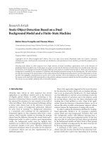
Figure 9 shows the TDP function of hops. In this figure,
the TDP of Shortest path routing using omni-direction
antennas increases rapidly, while the TDP of MinDP routing
algorithm increases adagio. In a scenario where the number
of detection systems is given, the TDP of Shortest path rout-
ing is much higher than that of MinDP routing algorithm.
It is reasonable that the more detection systems are within
the experiment area, the higher total detection probability is.
We can know from this figure that the transmission from the
source to the destination using omni-directional antennas
will be detected by detection systems definitely when the
number of detection systems is larger than 3 and the number
of hops is larger than 2. The average TDP of Shortest path
routing is 0.953 and the average TDP of MinDP routing
algorithm is 0.244. Hence, the MinDP routing algorithm
using directional antennas can reduce the total detection
probability by over 74%.
5. Related Work
Many protocols have been proposed to provide anonymity
in Internet, such as Crowds [24], Onion [25]. For ad hoc
1614121086420
Hop
Shortest path algorithm, detection system
= 1
MinDP routing algorithm, detection system
= 1
Shortest path algorithm, detection system
= 3
MinDP routing algorithm, detection system
= 3
Shortest path algorithm, detection system
= 5
MinDP routing algorithm, detection system
= 5
0
0.1
0.2
0.3
0.4
0.5
0.6
0.7
0.8
0.9
1
TDP
Figure 9: Total detection probability function of hops.
networks, although a number of papers about secure routing
have been proposed, such as SEAD [26], ARAN [27], AODV-
S[28], only a few papers are about anonymous routing
issue and few of them talk about directional antennas and
locations.
Zhu et al. proposed a secure routing protocol ASR for
MANET [29] to realize anonymous data transmission. ASR
makes sure that adversaries are not able to know the source
and the destination from data packets. ASR considers the
anonymity of addresses of the source and the destination in
a packet but not the physical location of the source. In ASR,
their solution make use of the shared secrets between any two
consecutive nodes. The goal of ASR is to hide the source and
destination information from data packets but not to protect
the transmission from being detected by hostile detection
systems.
ANODR is an secure protocol for mobile Ad hoc net-
works to provide route anonymity and location privacy [30].
For route anonymity, ANODR prevents strong adversaries
from tracing a packet flow back to its source or destination;
for location privacy, ANODR ensures that adversaries cannot
discover the real identities of local transmitters. However, the
location privacy ANODR provides is the identity of sender,
not the physical location privacy.
Zhang et al. proposed an anonymous on-demand rout-
ing protocol, MASK, for MANET [31]. In MASK, nodes
authenticate their neighboring nodes without revealing their
identities to establish pairwise secret keys. By utilizing the
secret keys, MASK achieves routing and forwarding task
without disclosing the identities of participating nodes.
Most secure routing protocols and anonymous routing
protocols employ authentication and secret key approaches
EURASIP Journal on Wireless Communications and Networking 7
Let PATH note the selected path and AvailablePath save all possible routing paths
Min
= 1
for i
= 1tok
for j
= 1tok
if i!
= j
Calculate dp(node
i
→ node
j
)
end if
end for
end for
/
∗
Generate all available routing paths and save routing paths to AvailablePath. A path is nodes
sequence like path
1
→ path
2
→ ··· → path
∗
x
/
GeneratePath(AvailablePath)
while AvailablePath !
= Empty
path
= GetPath(AvailablePath)
/
∗
Calculate the total detection probability (TDP) of path
∗
/
TDP
= 1 − (1 − dp(path
1
→ path
2
)) ···(1 − dp(path
{x−1}
→ path
x
))
if TDP <Minthen
Min
= TDP
PATH
= path
end if
DeletePath(AvailablePath,path)
/
∗
delete path from AvailablePath
∗
/
end while
PA TH is the selected routing path
Algorithm 1
to ensure the security. In a real wireless network, there is
no clear transmission range, hostile detection systems can
detect the transmitter’s signals even if it is very far away from
the transmitter. In this scenario, the detection system does
not need to pass the authentication, they just detect signals.
Hence, authentication cannot thwart hostile detection.
6. Conclusions
In an untrustworthy network, it is very important for the
transmitter to avoid being detected by adversaries. In this
paper, we propose a detection probability model to calculate
the probability of detecting a transmitter at any location
around the transmitter. Since signals from omnidirectional
antennas are radiated in all directions, hostile nodes at any
location can receive these electromagnetic waves, they have
probabilities to tell signals from noises. A directional antenna
could form a directional beam pointing to the receiver, and
only nodes in the main lobe beam region can receive signals
well. If a directional antenna employs less transmit power
than an omnidirectional antenna but provides the same
EIRP to the receiver, the directional antenna can reduce the
detection probability by over 96.7%. Therefore, we prefer to
employ directional antennas to relay data from the source to
the destination. Minimizing Detection Probability (MinDP)
routing algorithm we proposed can select a routing path that
has the lowest total detection probability. The simulation
results show that the MinDP routing algorithm can reduce
the TDP by over 74% so as to provide high security and
concealment for transmitters.
Acknowledgments
We would like to gratefully acknowledge ITA Project. Our
research was sponsored by the US Army Research Laboratory
and the U.K. Ministry of Defence.
References
[1] J F. Raymond, “Traffic analysis: protocols, attacks, design
issues, and open problems,” in Designing Privacy Enhancing
Technologies, H. Federath, Ed., Lecture Notes in Computer
Science, Springer, Berlin, Germany, 2001.
[2] G. W. Stimson, Introduction to Airborne Radar,SciTech,
Raleigh, NC, USA, 1998.
[3] T. S. Rappaport, Wireless Communications: Principles and
Practice, Prentice-Hall, Upper Saddle River, NJ, USA, 1996.
[4] J. E. Hill, “Gain of Directional Antennas,” Watkins-Johnson
Company, Tech-notes,1976.
[5] Z. Huang and C C. Shen, “A comparison study of omnidirec-
tional and directional MAC protocols for ad hoc networks,” in
Proceedings of the IEEE Global Telecommunications Conference
(GLOBECOM ’02), vol. 1, pp. 57–61, Taipei, Taiwan, Novem-
ber 2002.
[6] A. Spyropoulos and C. S. Raghavendra, “Energy efficient com-
munications in ad hoc networks using directional antennas,”
in Proceedings of the 21st Annual Joint Conference of the IEEE
Computer and Communications Societies (INFOCOM ’02), vol.
1, pp. 220–228, New York, NY, USA, June 2002.
[7] M. E. Steenstrup, “Neighbor discovery among mobile nodes
equipped with smart antennas,” in Proceedings of the Swedish
Workshop on Wireless Ad-Hoc Networks (ADHOC ’03), 2003.
8 EURASIP Journal on Wireless Communications and Networking
[8] Z. Zhang, “Pure directional transmission and reception
algorithms in wireless ad hoc networks with directional
antennas,” in Proceedings of the IEEE International Conference
on Communications (ICC ’05), vol. 5, pp. 3386–3390, Seoul,
Korea, May 2005.
[9] A. Nasipuri, S. Ye, J. You, and R. E. Hiromoto, “A MAC
protocol for mobile ad hoc networks using directional anten-
nas,” in Proceedings of the IEEE Wireless Communications and
Networking Conference (WCNC ’00), pp. 1214–1219, Chicago,
Ill, USA, September 2000.
[10] Y B. Ko, V. Shankarkumar, and N. H. Vaidya, “Medium
access control protocols using directional antennas in ad hoc
networks,” in Proceedings of the 19th Annual Joint Conference of
the IEEE Computer and Communications Societies (INFO COM
’00), vol. 1, pp. 13–21, Tel Aviv, Israel, March 2000.
[11] M. Takai, J. Martin, A. Ren, and R. Bagrodia, “Directional
virtual carrier sensing for directional antennas in mobile ad
hoc networks,” in Proceedings of the 3rd ACM International
Symposium on Mobile Ad Hoc Networking & Computing
(MobiHoc ’02), pp. 183–193, Lausanne, Switzerland, June
2002.
[12] L. Bao and J. J. Garcia-Luna-Aceves, “Transmission scheduling
in ad hoc networks with directional antennas,” in Proceedings
of the 8th Annual International Conference on Mobile Comput-
ing and Networking (MOBICOM ’02), pp. 48–58, Atlanta, Ga,
USA, September 2002.
[13] R. R. Choudhury, X. Yang, R. Ramanathan, and N. H. Vaidya,
“Using directional antennas for medium access control in ad
hoc networks,” in Proceedings of the 8th Annual International
Conference on Mobile Computing and Networking (MOBICOM
’02), pp. 59–70, Atlanta, Ga, USA, September 2002.
[14] A. Spyropoulos and C. S. Raghavendra, “Energy efficient com-
munications in ad hoc networks using directional antennas,”
in Proceedings of the 21st Annual Joint Conference of the IEEE
Computer and Communications Societies (INFOCOM ’02), vol.
1, pp. 220–228, New York, NY, USA, June 2002.
[15] A. Nasipuri, K. Li, and U. R. Sappidi, “Power consumption
and throughput in mobile ad hoc networks using directional
antennas,” in Proceedings of the 11th Internat ional Conference
on Computer Communications and Networks (IC3N ’02),
October 2002.
[16] R. Ramanathan, J. Redi, C. Santivanez, D. Wiggins, and
S. Polit, “Ad hoc networking with directional antennas: a
complete system solution,” IEEE Journal on Selected Areas in
Communications, vol. 23, no. 3, pp. 496–506, 2005.
[17] S. Yi, Y. Pei, and S. Kalyanaraman, “On the capacity improve-
ment of ad hoc wireless networks using directional antennas,”
in Proceedings of the 4th ACM International Symposium on
Mobile Ad Hoc Networking and Computing (MobiHoc ’03),pp.
108–116, Annapolis, Md, USA, June 2003.
[18] B. Liu, Z. Liu, and D. Towsley, “On the capacity of hybrid
wireless networks,” in Proceedings of the 22nd Annual Joint
Conference of the IEEE Computer and Communications Soci-
eties (INFOCOM ’03), vol. 2, pp. 1543–1552, San Francisco,
Calif, USA, March-April 2003.
[19] IEEE Std, 100 The Authoritative Dictionary of IEEE Standards
Ter ms, The Institute of Electrical and Electronics Engineers,
New York, NY, USA, 7th edition, 2000.
[20] C. Balanis, Antenna Theory, John Wiley & Sons, New York, NY,
USA, 3rd edition, 2005.
[21] G. Breed, “Bit error rate: fundamental concepts and measure-
ment issues,” High Frequency Electronics, vol. 2, no. 1, pp. 46–
47, 2003.
[22] Breeze Wireless Communications Ltd, Radio Signal Propaga-
tion, .
[23] Federal Standard 1037C, “Telecommunications: Glossary of
Telecommunication Terms,” National Communication System
Technology & Standards Division, 1991.
[24] M. K. Reiter and A. D. Rubin, “Crowds: anonymity for web
transactions,” Communications of the ACM,vol.42,no.2,pp.
32–48, 1999.
[25] M.G.Reed,P.F.Syverson,andD.M.Goldschlag,“Anonymous
connections and onion routing,” IEEE Journal on Selected
Areas in Communications, vol. 16, no. 4, pp. 482–493, 1998.
[26] Y C. Hu, A. Perrig, and D. B. Johnson, “Ariadne: a secure on-
demand routing protocol for ad hoc networks,” in Proceedings
of the 8th Annual International Conference on Mobile Comput-
ing and Networking (MobiHoc ’02), pp. 12–23, Atlanta, Ga,
USA, September 2002.
[27] K. Sanzgiri, B. Dahill, B. N. Levine, C. Shields, and E.
M. Belding-Royer, “A secure routing protocol for ad hoc
networks,” in Proceedings of the 10th IEEE International
Conference on Network Protocols (ICNP ’02),Paris,France,
November 2002.
[28] H. Yang, X. Meng, and S. Lu, “Self-organized network-layer
security in mobile ad hoc networks,” in Proceedings of the ACM
Workshop on Wireless Security, pp. 11–20, Atlanta, Ga, USA,
September 2002.
[29] B. Zhu, Z. Wan, M. S. Kankanhalli, F. Bao, and R. H. Deng,
“Anonymous secure routing in mobile ad-hoc networks,” in
Proceedings of the 29th Annual IEEE International Conference
on Local Computer Networks (LCN ’04), pp. 102–108, Tampa,
Fla, USA, November 2004.
[30] J. Kong and X. Hong, “ANODR: anonymous on demand
routing with untraceable routes for mobile ad-hoc networks,”
in Proceedings of the 4th ACM International Symposium on
Mobile Ad Hoc Networking and Computing (MobiHoc ’03),pp.
291–302, Annapolis, Md, USA, June 2003.
[31] Y. Zhang, W. Liu, and W. Lou, “Anonymous communications
in mobile ad hoc networks,” in Proceedings of the 24th Annual
Joint Conference of the IEEE Computer and Communications
Societies(INFOCOM’05), vol. 3, pp. 1940–1951, Miami, Fla,
USA, March 2005.