Báo cáo hóa học: "Research Article Prototyping Advanced Control Systems on FPGA" pot
Bạn đang xem bản rút gọn của tài liệu. Xem và tải ngay bản đầy đủ của tài liệu tại đây (1.99 MB, 12 trang )
Hindawi Publishing Corporation
EURASIP Journal on Embedded Systems
Volume 2009, Article ID 897023, 12 pages
doi:10.1155/2009/897023
Research Article
Prototyping Advanced Control Systems on FPGA
St
´
ephane Simard, Jean-Gabriel Mailloux, and Rachid Beguenane
Department of Applied Sciences, University of Quebec at Chicoutimi, 555 boul. de l’Universit
´
e, Chicoutimi, QC, Canada G7H 2B1
Correspondence should be addressed to Rachid Beguenane,
Received 19 June 2008; Accepted 3 March 2009
Recommended by Miriam Leeser
In advanced digital control and mechatronics, FPGA-based systems on a chip (SoCs) promise to supplant older technologies, such
as microcontrollers and DSPs. However, the tackling of FPGA technology by control specialists is complicated by the need for
skilled hardware/software partitioning and design in order to match the performance requirements of more and more complex
algorithms while minimizing cost. Currently, without adequate software support to provide a straightforward design flow, the
amount of time and efforts required is prohibitive. In this paper, we discuss our choice, adaptation, and use of a rapid prototyping
platform and design flow suitable for the design of on-chip motion controllers and other SoCs with a need for analog interfacing.
The platform consists of a customized FPGA design for the Amirix AP1000 PCI FPGA board coupled with a multichannel analog
I/O daughter card. The design flow uses Xilinx System Generator in Matlab/Simulink for system design and test, and Xilinx
Platform Studio for SoC integration. This approach has been applied to the analysis, design, and hardware implementation of
a vector controller for 3-phase AC induction motors. It also has contributed to the development of CMC’s MEMS prototyping
platform, now used by several Canadian laboratories.
Copyright © 2009 St
´
ephane Simard et al. This is an open access article distributed under the Creative Commons Attribution
License, which permits unrestricted use, distribution, and reproduction in any medium, provided the original work is properly
cited.
1. Introduction
The use of advanced control algorithms depends upon being
able to perform complex calculations within demanding
timing constraints, where system dynamics can require
feedback response in as short as a couple tens of microsec-
onds. Developing and implementing such capable feedback
controllers is currently a hard goal to achieve, and there is
much technological challenge in making it more affordable.
Thanks to major technological breakthroughs in recent years,
and to sustained rapid progress in the fields of very large
scale integration (VLSI) and electronic design automation
(EDA), electronic systems are increasingly powerful [1,
2]. In the latter paper, it is rightly stated that FPGA
devices have reached a level of development that puts
them on the edge of microelectronics fabrication technology
advancements. They provide many advantages with respect
to their nonreconfigurable counterparts such as the general
purpose micropocessors and DSP processors. In fact, FPGA-
based digital processing systems achieve better performance-
cost compromise, and with a moderate design effort they
can afford the implementation of a powerful and flexible
embedded SoCs. Exploiting the FPGA technology benefits
for industrial electrical control systems has been the source of
intensive research investigations during last decade in order
to boost their performances at lower cost [3, 4]. There is
still, however, much work to be done to bring such power
in the hands of control specialists. In [5], it is stated that the
potential of implementing one FPGA chip-based controller
has not been fully exploited in the complicated motor
control or complex converter control applications. Until
now, most related research works using FPGA devices are
focusing on designing specific parts mainly to control power
electronic devices such as space vector pulse width modula-
tion (SVPWM) and power factor correction [6, 7]. Usually
these are implemented on small FPGAs while the main
control tasks are realised sequentially by the supervising
processor system, basically the DSP. Important and constant
improvement in FPGA devices, synthesis, place-and-route
tools, and debug capabilities has made FPGA prototyping
more available and practical to ASIC/SoC designers than
ever before. The validation of their hardware and software
on a common platform can be accomplished using FPGA-
based prototypes. Thanks to the existing and mature tools
2 EURASIP Journal on Embedded Systems
that provide automation while maintaining flexibility, the
FPGA prototypes make it now possible for ASIC/SoC designs
to be delivered on time at minimal budget. Consequently,
FPGA-based prototypes could be efficiently exploited for
motion control applications to permit an easy modification
of the advanced control algorithms through short-design
cycles, simple simulation, and rapid verification. Still the
implementation of FPGA-based SoCs for motion control
results in very complex tasks involving SW and HW skilled
developers. The efficient IP integration constitutes the main
difficulty from hardware perspective while in software side
the issue is the complexity of debugging the software that
runs under real-time operating system (RTOS), in real hard-
ware. This paper discusses the choice, adaptation, and use of
a rapid prototyping platform and design flow suitable for the
design of on-chip motion controllers and other SoCs with a
need for analog interfacing. Section 2 describes the chosen
prototyping platform and the methodology that supports
embedded application software coupled with custom FPGA
logic and analog interfacing. Section 3 presents the strategy
for simulating and prototyping any control algorithm using
Xilinx system Generator (XSG) along with Matlab/Simulink.
A vector control for induction motor is taken as a running
example to explain some features related to the cosimulation.
Section 4 describes the process of integrating the designed
controller, once completely debugged, within an SoC archi-
tecture using Xilinx Platform Studio (XPS) and targeting
the chosen FPGA-based platform. Section 5 discusses the
complex task of PCI initialization of the analog I/O card
and controller setup by software under embedded Linux
operating system. Section 6 takes the induction motor vector
control algorithm as an application basis to demonstrate
the usefulness of the chosen FPGA-based SoC platform to
design/verify on-chip motion controllers. The last section
concludes the paper.
2. The FPGA-Based Prototyping Platform for
On-Chip Motion Controllers
With the advent of a new generation of high-performance
and high-density FPGAs offering speeds in the 100 seconds
of MHz and complexities of up to 2 megagates, the FPGA-
based prototyping becomes appropriate for verification of
SoC and ASIC designs. Consequently the increasing design
complexities and the availability of high-capacity FPGAs
in high-pin-count packages are motivating the need for
sophisticated boards. Board development has become a task
that demands unique expertise. That is one reason why
commercial off-the-shelf (COTS) boards are quickly becom-
ing the solution of choice because they are closely related
to the implementation and debugging tools. During many
years, and under its System-on-Chip Research Network
(SOCRN) program, CMC Microsystems provided canadian
universities with development tools, various DSP/Embedded
Systems/multimedia boards, and SoC prototyping boards
such as Amirix AP1000 PCI FPGA development platform.
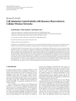
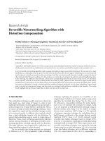
Inordertosupportourresearchonon-chipmotion
controllers, we have managed the former plateform, a host
Analog I/Q
daughter card
AP1000 board
Digital outputs
from the FPGA
Figure 1: Rapid prototyping station equiped with FPGA board and
multichannel analog I/O daughter card.
PC (3.4 GHz Xeon CPU with 2.75 GB of RAM) equiped
with the Amirix AP1000 PCI FPGA development board,
to support a multichannel analog I/O PMC daughter card
(Figure 1) to communicate with exterior world.
The AP1000 has lots of features to support complex
system prototyping, including test access and expansion
capabilities. The PCB is a 64-bit PCI card that can be
inserted in a standard expansion slot on a PC motherboard
or PCI backplane. Use of the PMC site requires a second
chassis slot on the backside of the board and an optional
extender card to provide access to the board I/O. The AP1000
platform includes a Xilinx Virtex-II Pro XC2VP100 FPGA
and is connected to dual banks of DDR SDRAM (64 MB)
and SRAM (2 MB), Flash Memory (16 MB), Ethernet and
other interfaces. It is configured as a single board computer
based on two embedded IBM PowerPC processors, and it is
providing an advanced design starting point for the designer
to improve time-to-market and reduce development costs.
The analog electronics are considered modular, and can
either be external or included on the same chip (e.g., when
fabricated into an ASIC). On the prototyping platform,
of course, they are supplied by the PMC daughter card.
It is a General Standards PMC66-16AISS8A04 analog I/O
board featuring twelve 16-bit channels: eight simultaneously
sampled analog inputs, and four analog outputs, with input
sampling rates up to 2.0 MSPS per channel. It acts as a two-
way analog interface between the FPGA and lab equipment,
connected through an 80-pin ribbon cable and a breakeout
board to the appropriate ports of the power module.
The application software is compiled with the free
Embedded Linux Development Kit (ELDK) from DENX
Software Engineering. Since it runs under such a complete
operating system as Linux, it can perform elaborated func-
tions, including user interface management (via a serial
link or through networking), and real-time supervision and
adaptation of a process such as adaptive control.
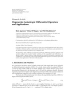
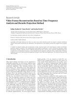
The overall platform is very well suited to FPGA-in-
the-loop control and SoC controller prototyping (Figure 2).
The controller can either be implemented completely in
digital hardware, or executed on an application-specific
instruction set processor (ASIP). The hardware approach has
a familiar design flow, using the Xilinx System Generator
EURASIP Journal on Embedded Systems 3
AC
induction
motor
Power
module
Digital
outputs
(PMW,etc)
RJ45
RS232
Xcvr
PMC Ethernet RJ45
PCI
bridge
Bridge
Bridge
External
local
bridge
Interrupt
controller
UART
PLB
OPB
FPGA Virtex-II Pro XC2VP100
AP1000 FPGA board
PowerPC
405
SDRAM
controller
User
logic
Interface
Application
software + HW logic driver
under Linux
General standards PMC analog
I/Q card with 12 16 bit analog
channels: 4 outputs, and 8
simultaneously sampled inputs
-
Figure 2: Architecture of the embedded platform driving a power
system (schematic not to scale).
(XSG) blockset and hardware/software cosimulation features
in Matlab/Simulink. An ASIP specially devised for advanced
control applications is currently under development within
our laboratory.
3. Matlab/Simulink/XSG Controller Design
It is well known that simulation of large systems within
system analysis and modelling software environments takes
a prohibitive amount of time. The main advantage of a rapid
prototyping design flow with hardware/software cosimula-
tion is that it provides the best of a system analysis and
modelling environment while offering adequate hardware
acceleration.
Hardware/software cosimulation has been introduced
by major EDA vendors around year 2000, combining
Matlab/Simulink, the computing, and Model-Based Design
software, with synthesizable blocksets and automated hard-
ware synthesis software such as DSP Builder from Altera,
and System Generator from Xilinx (XSG). Such a design
flow reduces the learning time and development risk for
DSP developers, shortens the path from design concept to
working hardware, and enables engineers to rapidly create
and implement innovative, high-performance DSP designs.
The XSG cosimulation feature allows the user to run a
design on the FPGA found on a certain platform. An impor-
tant advantage of XSG is that it allows for quick evaluation
of system response when making changes (e.g., changing
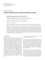
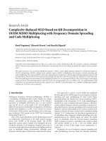
coefficient and data widths). As the AP1000 is not supported
by XSG among the preprogrammed cosimulation targets, we
use the Virtex-4 ML402 SX XtremeDSP Evaluation Platform
instead (Figure 3). The AP1000 is only targetted at the SoC
integration step (see Section 4).
Figure 3: Virtex-4 ML402 SX XtremeDSP evaluation platform.
We begin with a conventional, floating-point, simu-
lated control system model, and corresponding fixed-point
hardware representation is then constructed using the XSG
blockset, leading to a bit-accurate FPGA hardware model
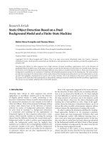
(Figure 4), and XSG generates synthesizable HDL targetting
Xilinx FPGAs. The XSG design, simulation, and test pro-
cedure is briefly outlined below. Power systems including
motor drives can be simulated using the SimPowerSystems
(SPS) blockset in Simulink.
(1) Start by coding each system module individually with
the XSG blockset.
(2) Import any user-designed HDL cores.
(3) Adjust the fixed-point bit precisions (including bit
widths and binary point position) for each XSG block
of the system.
(4) Use the Xilinx Gateway blocks to interface a floating-
point Simulink model with a fixed-point XSG design.
The Gateway-in and Gateway-out blocks, respec-
tively, convert inputs from Simulink to XSG and
outputs from XSG to Simulink.
(5) Test system response using the same input stimuli for
an equivalent XSG design and Simulink model with
automatic comparision of their respective outputs.
Commonly, software simulation of a complete drive
model, for a few seconds of results, could take a couple of
days of computer time. Hardware/software cosimulation can
be used to accelerate the process of controller simulation,
thus reducing the computing time to about a couple of hours.
It also ensures that the design will respond correctly once
implemented in hardware.
4. System-on-Chip Integration in Xilinx
Platform Studio
FPGA design and the SoC architecture are managed with
Xilinx Platform Studio (XPS), targetting the AP1000. We
have customized the CMC-modified Amirix baseline design
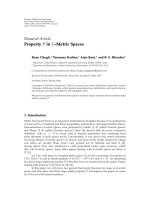
4 EURASIP Journal on Embedded Systems
Hardware
library
component
Baseline
SoC
architecture
Application-
specification
hardware
components
Hardware
design flow
Functional
simulation
Integration of the
components
to the SoC
Controller
synthesis
in XSG
Matlab/Simulink
modeling
Hardware/software
co-simulation
Software
libraries
and drivers
Source-level
integration
Low-level
software
simulation
Application-
specific code
Embedded Linu
x
operation system
Software
design flow
FPGA prototype
Co-simulation data link
Figure 4: Controller-on-chip design flow.
to support analog interfacing, user logic on the Processor
Local Bus (PLB), and communication with application
software under embedded Linux. XPS generates the corre-
sponding .bin file, which is then transferred to the Flash
configuration memory on the AP1000. The contents of this
memory is used to reconfigure the FPGA. We have found
an undocumented fact that, on the AP1000, this approach
is the only practicable way to program the FPGA. JTAG
programming is proved inconvenient, because it suppresses
the embedded Linux, which is essential to us for PCI
initialization. Once programmed, user logic awaits a start
signal from our application software following analog I/O
card initialization.
To accelerate the logic synthesis process, the mapper and
place and route options are set to STD (standard) in the
implementation options file (etc/fast
runtime.opt), found in
the Project Files menu. If the user wants a more aggressive
effort, these options should be changed to HIGH, which
requires much more time. Our experiments have shown that
it typically amounts to several hours.
4.1. Bus Interfacing. The busses implemented in FPGA logic
follow the IBM CoreConnect standard. It provides master
and slave operation modes for any instanciated hardware
module. The most important system busses are the Processor
Local Bus (PLB), and the On-chip Peripheral Bus (OPB).
The implementation of the vector control scheme
requires much less of generality, and deletes some commu-
nication stages that might be used in other applications. It is
easier to start from such a generic design, dropping unneeded
features, than to start from scratch. This way, one can quickly
progress from SoC architecture in XPS down to a working
controller on the AP1000.
4.1.1. Slave Model Register Read Mux. The baseline XPS
design provides the developer with a slave model register
read multiplexer. This allows to decide which data isprovided
when a read request is sent to the user logic peripheral by
another peripheral in the system. While a greater number
may be used, our pilot application, the vector control, only
use four slave registers. The user logic peripheral has a
specific base address (C
BASEADDR), and the four 32-
bit registers are accessed through C
BASEADDR + register
offset. In this example, C
BASEADDR + 0x0 corresponds
to the control and status register, which is composed of the
following bits:
0–7 : the DIP switches on the AP1000 for
debugging purposes,
8 : used by user software to reset, start, or
stop the controller,
9–31 : reserved.
As for the other 3 registers, they correspond to
C
BASEADDR + 0x4: Output to analog
channel 1
C
BASEADDR + 0x8: Output to analog
channel 2
C
BASEADDR + 0xC: Reserved (often used for
debugging purposes)
4.1.2. Master Model Control. The master model control
state machine is used to control the requests and responses
between the user logic peripheral and the analog I/O card.
The latter is used to read the input currents and voltages
for vector control operation. The start signal previously
mentioned in slave register 0 is what gets the state machine
out of IDLE mode, and thus starts the data acquisition
process. In this specific example, the I/O card is previously
initialized by the embedded application software, relieving
the state machine of any initialization code. Analog I/O
EURASIP Journal on Embedded Systems 5
initialization sets a lot of parameters, including how many
active channels are to be read.
The state machine operates in the following way
(Figure 5).
(1) The user logic waits for a start signal from the user
through slave register 0.
(2) The different addresses to access the right AIO card
fields are set up, namely, the BCR and read buffer.
(3) A trigger is sent to the AIO card to buffer the values
of all desired analog channels.
(4) A read cycle is repeated for the number of active
channels previously defined.
(5) Once all channels have been read, the state machine
falls back to trigger state, unless the user chooses to
stop the process using slave register 0.
4.2. Creating or Importing User Cores. User-designed logic
and other IPs can be created or imported into the XPS design
following this procedure.
(1) Select Create or Import Peripheral from the Hard-
ware menu, and follow the wizard (unless otherwise
stated below, the default options should be accepted).
(2) Choose the preferred bus. In the case of our vector
controller, it is connected to the PLB.
(3) For PLB interfacing, select the following IPIF ser-
vices:
(a) burst and cacheline transaction support,
(b) master support,
(c) S/W register support.
(4) The User S/W Regitser data width should be 32.
(5) Accept the other wizard options as default, then click
Finish.
(6) You should find your newly created/imported core in
the Project Repository of the IP Catalog; right click
on it, and select Add IP.
(7) Finally go to the Assembly tab in the main System
Assembly View, and set the base address (e.g.,
0x2a001000), the memory size (e.g., 512), and the bus
connection (e.g., plb
bus).
4.3. Instantiating a Netlist Core. Using HDL generated by
System Generator may be inconvenient for large control
systems described with the XSG blockset, as it can require
a couple of days of synthesis time. System Generator
can be asked to produce a corresponding NGC binary
netlist file instead, which is then treated as a black box
to be imported and integrated into an XPS project. This
considerably reduces the synthesis time needed. The process
of instantiating a Netlist Core in a custom peripheral (e.g.,
user
logic.vhd), performed following the steps documented
in XPS user guide.
IDLE
Adresses
setup
AIO
trigger
PAUSE
Start signal
Trigger ACK
All channels
read
One active channel
read
Read another
active channel
Stop signal
Read
cycle
Setup completed
BCR and
status
Figure 5: Master model state machine.
Table 1: The Two Intel StrataFlash Flash memory devices.
Bank Address Size Mode Description
1 0x20000000 0x1000000 (16 MB) 16 Program Flash
2 0x24000000 0x1000000 (16 MB) 8 Config. Flash
Table 2: AP1000 flash configurations.
Region Bank Sectors Description
0 2 0–39 Configuration 0
1 2 40–79 Configuration 1
2 2 80–127 Configuration 2 (Default Config.)
4.4. BIN File Generation and FPGA Configuration. To c o n fi g -
ure the FPGA, a BIN file must be generated from the XSG
project. Since JTAG programming disables the embedded
Linux, the BIN file must be downloaded directly to onboard
Flash memory. There are two Intel Strataflash Flash memory
devices on the AP1000, one for the configuration, and one
for the U-boot bootstrap code (which should not be crushed)
(Ta bl e 1).
The configuration memory (Table 2 ) is divided into three
sections. Section 2 is the default Amirix configuration, and
should not be crushed. Downloading the BIN file to memory
is done through a network cable using the TFTP protocol.
For this purpose, a TFTP server must be set up on the
host PC. The remote side of the protocol is managed by
U-boot on the AP1000. Commands to U-boot to initiate
the transfer and to trigger FPGA reconfiguration from a
designated region are entered by the user through a serial link
terminal program. Here is the complete U-boot command
sequence:
setenv serverip 132.212.202.166
setenv ipaddr 132.212.201.223
erase 2 : 0–39
Send tftp 00100000 download.bin
Send cp.b 00100000 24000000 00500000
Send swrecon
6 EURASIP Journal on Embedded Systems
5. Application Software and Drivers
One of the main advantages of using an embedded Linux
system is the ability to perform the complex task of PCI
initialization. In addition, it allows for application software
to provide elaborated interfacing and user monitoring
through appropriate software drivers. Initialization of the
analog I/O card on the PMC site and controller setup are
among such tasks that are best performed by software.
5.1. Linux Device Drivers Essentials. Appropriate device
drivers have to be written in order to use daughter cards
(such as an analog I/O board) or custom hardware com-
ponents on a bus internal to the SoC, and be able to
communicate with them from the embedded Linux. Drivers
and application software for the AP1000 can be developed
with the free Embedded Linux Development Kit (ELDK)
from DENX Software Engineering, Germany. The ELDK
includes the GNU cross development tools, along with
prebuilt target tools and libraries to support the target
system. It comes with full source code, including all patches,
extensions, programs, and scripts used to build the tools.
A complete discussion on writing Linux device drivers is
beyond the scope of this paper, and this information may be
found elsewhere, such as in [8]. Here, we only mention a few
important issues relevant to the pilot application.
To support all the required functions when creating a
Linux device driver, the following includes are needed:
#include <linux/config.h>
#include <linux/module.h>
#include <linux/pci.h>
#include <linux/init.h>
#include <linux/kernel.h>
#include <linux/slab.h>
#include <linux/fs.h>
#include <linux/ioport.h>
#include <linux/ioctl.h>
#include <linux/byteorder/
big
endian.h>
#include <asm/io.h>
#include <asm/system.h>
#include <asm/uaccess.h>
5.2. PCI Access to the Analog I/O Board . The pci
find
device() function begins or continues searching for a PCI
device by vendor/device ID. It iterates through the list of
known PCI devices, and if a PCI device is found with
a matching vendor and device, a pointer to its device
structure is returned. Otherwise, NULL is returned. For
the PMC66-16AISS8A04, the vendor ID is 0x10e3, and the
device ID is 0x8260. The device must then be initialized with
pci
initialize device() before it can be used by the driver.
The start address of the base address registers (BARs) can be
obtained using pci
resource start(). In the example, we get
BAR 2 which gives access to the main control registers of the
PMC66-16AISS8A04.
volatile u32
∗base addr;
struct pci
dev ∗dev;
struc resource
∗ctrl res;
dev = pci
find device(VENDORID,
DEVICEID, NULL);
.
.
.
pci
enable device (dev);
get
revision (dev);
base
addr = (volatile u32 ∗)
pci
resource start (dev, 2);
ctrl
res = request mem region (
(unsigned long)base
addr,
0x80L,"control");
bcr = (u32
∗) ioremap nocache (
(unsigned long)base
addr,
0x80L);
The readl() and writel() functions are defined to access
PCI memory space in units of 32 bits. Since the PowerPC
is big-endian while the PCI bus is by definition little-
endian, a byte swap occurs when reading and writing PCI
data. To ensure correct byte order, the le32
to cpu() and
cpu
to le32() functions are used on incoming and outgoing
data. The following code example defines some macros to
read and write the Board Control Register, to read data from
the analog input buffer, and to write to one of the four analog
output channels.
volatile u32
∗bcr;
#define GET
BCR() (le32 to cpu(\\
readl (bcr)))
#define SET
BCR(x) writel(\\
cpu to le32(x), bcr)
#define ANALOG
IN()le32 to cpu(\\
readl (&bcr[ANALOG INPUT BUF]))
#define ANALOG
OUT(x,c) writel(\\
cpu to le32(x), \\
&bcr[ANALOG OUTPUT CHAN 00+c])
5.3. Cross-Compilation with the ELDK. To properly compile
with the ELDK, a makefile is required. Kernel source code
should be available in KERNELDIR to provide for essential
includes. The version of the preinstalled kernel on the
AP1000 is Linux 1.4. Example of a minimal makefile:
TARGET= thetarget
OBJS= myobj.o
#EDIT THE FOLLOWING TO POINT TO
#THE TOP OF THE KERNEL SOURCE TREE
KERNELDIR =
∼
/kernel-sw-003996-01
CC = ppc
4xx−gcc
LD = ppc
4xx−ld
EURASIP Journal on Embedded Systems 7
DEFINES =
−D
—
KERNEL
—
−DMODULE\\
−
DEXPORT SYMTAB
INCLUDES=
−I$(KERNELDIR)/include\\
−
I$(KERNELDIR)/include/Linux\\
−
I$(KERNELDIR)/include/asm
FLAGS =
−fno-strict-aliasing \\
−
fno-common\\
−
fomit-frame-pointer\\
−
fsigned-char
CFLAGS = $(DEFINES) $(WARNINGS)
\\
$(INCLUDES) $(SWITCHES)\\
$(FLAGS)
all: $(TARGET).o Makefile
$(TARGET).o: $(OBJS)
$(LD)
−r-o$@$
∧
5.4. Software and Driver Installation on the AP1000. For ease
of manipulation, user software and drivers are best carried on
a CompactFlash card, which is then inserted in the back slot
of the AP1000 and mounted into the Linux file system. The
drivers are then intalled, and the application software started,
as follows:
mount /dev/discs/disc0/part1 /mnt
insmod /mnt/logic2/hwlogic.o
insmo /mnt/aio.o
cd /dev
mknod hwlogic c 254 0
mknod aio c 253 0
/mnt/cvecapp
6. Application: AC Induction Motor Control
Given their well-known qualities of being cheap, highly
robust, efficient, and reliable, AC induction motors currently
constitute the bulk of the motion industry park. From the
control point of view, however, these motors have highly
nonlinear behavior.
6.1. FPGA-Based Induction Motor Vector Control. The
selected control algorithm for our pilot application is the
rotor-flux oriented vector control of a three-phase AC
induction motor of the squirrel-cage type. It is the first
method which makes it possible to artificially give some
linearity to the torque control of induction motors [9].
RFOC algorithm consists in partial linearization of the
physical model of the induction motor by breaking up the
stator current i
s
into its components in a suitable reference
frame (d, q). This frame is synchronously revolving along
with the rotor flux space vector in order to get a separate
control of the torque and rotor flux. The overall strategy
then consists in regulating the speed while maintaining
the rotor flux constant (e.g., 1 Wb). The RFOC algorithm
is directly derived from the electromechanical model of
a three-phase, Y-connected, squirrel-cage induction motor.
This is described by equations in the synchronously rotating
reference frame (d, q)as
u
sd
= R
s
i
sd
+ σL
s
d
dt
i
sd
−σL
s
ωi
sq
+
M
L
r
d
dt
Ψ
r
,
D
d
u
sq
= R
s
i
sq
+ σL
s
d
dt
i
sq
+σL
s
ωi
sd
+
M
L
r
ωΨ
r
,
D
q
d
dt
Ψ
r
=
R
r
L
r
(
Mi
sd
−Ψ
r
)
,
ω
= P
p
ω
r
+
MR
r
Ψ
r
L
r
i
sq
,
dω
r
dt
=
3
2
P
p
M
JL
r
Ψ
r
i
sq
−
D
J
ω
r
−
T
l
J
,
(1)
where u
sd
and u
sq
are d and q components of stator voltage
u
s
, i
sd
,andi
sq
are d and q components of stator current i
s
, Ψ
r
is the modulus of rotor flux modulus, and θ is the angular
position of rotor flux, ω is the synchronous angular speed of
the (d, q) reference frame (ω
= dθ/dt), and L
s
, L
r
,andM
are stator, rotor, and mutual inductances, R
s
, R
r
are stator
and rotor resistances, σ is the leakage coefficient of the motor,
and P
p
is the number of pole pairs, ω
r
is the mechanical rotor
speed, D is damping coefficient, J is the inertial momentum,
and T
l
is torque load.
6.2. RFOC Algorithm. The derived expressions for each block
composing the induction motor RFOC scheme, as shown in
Figure 6, are given as follows:
Speed PI Controller:
i
∗
sq
= k
p
v
v
+ k
i
v
v
dt;
v
= ω
∗
r
−ω
r
. (2)
Rotor Flux PI Controller:
i
∗
sd
= k
p
f
f
+ k
i
f
f
dt;
f
= Ψ
∗
r
−Ψ
r
. (3)
Rotor Flux Estimator:
Ψ
r
=
Ψ
2
rα
+ Ψ
2
rβ
,
(4)
cos θ
=
Ψ
rα
Ψ
r
,sinθ =
Ψ
rβ
Ψ
r
,(5)
with
Ψ
rα
=
L
r
M
(
Ψ
sα
−σL
s
i
sα
)
, Ψ
rβ
=
L
r
M
Ψ
sβ
−σL
s
i
sβ
,
(6)
Ψ
sα
=
(
u
sα
−R
s
i
sα
)
, Ψ
sβ
=
u
sβ
−R
s
i
sβ
,(7)
8 EURASIP Journal on Embedded Systems
V
v
v
u
u
sp
sp
sp
sp
sp
u
u
i
sp
i
i
i
DC
sd
sq
sd
sq
al
bh
ch
bl
cl
sa
sb
sa
ah
sb
sd
sq
Decoupling
Rotor
flux
estimator
Speed PI
controller
Rotor flux
PI controller
Q-current
PI controller
D-current
PI controller
Park
transform
Speed measure
Inverse
transform
park
SVPWM
module
gating
Clarke
transform
Clarke
transform
IM
+
−
+
+
+
+
+
+
+
−
−
−
ω
∗
r
Ψ
∗
r
i
∗
sq
i
∗
sd
u
∗
sα
u
∗
sβ
cos θ
sin θ
Ψ
r
ω
ω estimator
ω
r
i
sα
i
sβ
u
sα
u
sβ
3-φ
voltage
PWM
inverter
Figure 6: Conceptual block diagram of the system.
and using Clarke transformation
i
sα
= i
sa
, i
sβ
=
1
√
3
i
sa
+
2
√
3
i
sb
,
(8)
u
sα
= u
sa
, u
sβ
=
1
√
3
u
sa
+
2
√
3
u
sb
. (9)
To be noticed that sine and cosine, of (5), sum up to a
division, and therefore do not have to be directly calculated.
Current PI Controller:
v
sd
= k
p
i
i
sd
+ k
i
i
i
sd
dt;
i
sd
= i
∗
sd
−i
sd
, (10)
v
sq
= k
p
i
i
sq
+ k
i
i
i
sq
dt;
i
sq
= i
∗
sq
−i
sq
. (11)
Decoupling:
u
sd
= σL
s
v
sd
+ D
d
; u
sq
= σL
s
v
sq
+ D
q
, (12)
with
D
d
=−σL
s
ωi
sq
+
M
L
r
d
dt
Ψ
r
, D
q
= +σL
s
ωi
sd
+
M
L
r
ωΨ
r
.
(13)
Omega (ω)Estimator:
ω
= P
p
ω
r
+
MR
r
Ψ
r
L
r
i
sq
. (14)
Park Transformation:
⎡
⎣
i
s
d
i
s
q
⎤
⎦
=
⎡
⎣
cos θ sinθ
−sin θ cos θ
⎤
⎦
⎡
⎣
i
s
α
i
s
β
⎤
⎦
. (15)
InverseParkTransformation:
⎡
⎣
u
∗
s
α
u
∗
s
β
⎤
⎦
=
⎡
⎣
cos θ −sinθ
sin θ cos θ
⎤
⎦
⎡
⎣
u
s
d
u
s
q
⎤
⎦
. (16)
In the above equations, for x standing for any variable
such as voltage u
s
,currenti
s
or rotor flux Ψ
r
, we have the
following.
(x
∗
) Input reference corresponding to x.
(
x
) Error signal corresponding to x.
(k
p
x
, k
i
x
) Proportional and integral parameters corre-
sponding to the PI controller of x.
(x
a
, x
b
, x
c
) a, b,andc three-phase components of x in the
stationary reference frame.
(x
α
, x
β
) α and β two-phase components of x in the
stationary reference frame.
(x
d
, x
q
) d and q components of x in the synchronously
rotating frame.
The RFOC scheme features vector transformations
(Clarke and Park), 4 IP regulators, and space-vector PWM
generator (SVPWM). This algorithm is of interest for its
good performances, and because it has a fair level of
complexity which benefits from a very-high-performance
FPGA implementation. In fact, FPGAs make it possible to
execute the loop of a complicated control algorithm in a
matter of a few microseconds. The first prototype of such
a controller has been developed using the method and
platform described here, and has been implemented entirely
in FPGA logic [10].
Commonly used mediums prior to the advent of today’s
large FPGAs, including the use of DSPs alone and/or special-
ized microcontrollers, led to a total cycle time of more than
100 μs for vector control. This lead to switching frequencies
EURASIP Journal on Embedded Systems 9
Dynamo with
optical speed
encoder
Encoder
cable
Resistive load
Power
supply
Cable interface
to analog I/O card
Digital I/O
from FPGA
High-voltage
power module
Squirrel-cage
induction motor
Figure 7: Experimental setup with power electronics, induction
motor, and loads.
in the range of 1–5 kHz, which produced disturbing noise in
the audible band. With today’s FPGAs, it becomes possible to
fit a very large control system on a single chip, and to support
very high switching frequencies.
6.3. Validation of RFOC Using Cosimulation with XSG. A
strong hardware/software cosimulation environment and
methodology is necessary to allow validation of the hardware
design against a theoretical control system model.
As mentioned is Section 3, the design flow which has
been adopted in this research uses the XSG blockset in
Matlab/Simulink. XSG model of RFOC block is built up
from (2)to(16) and the global system architecture is shown
in Figure 8 where Gateway-in and Gateway-out blocks pro-
vide the necessary interface between the fixed-point FPGA
hardware that include the RFOC and Space Vector Pulse
Width Modulation (SVPWM) algorithms and the floating-
point Simulink blocksets mainly the SimPowerSystems (SPS)
models. In fact to make the simulations more realistic, the
three-phase AC induction motor and the corresponding
Voltage Source Inverter were modelled in Simulink using
the SPS blockset, which is robust and well proven. To be
noticed that SVPWM is a widely used technique for three-
phase voltage-source inverters (VSI), and is well suited for
AC induction motors.
At runtime, the hardware design (RFOC and SVPWM)
is automatically downloaded into the actual FPGA device,
and its response can then be verified in real-time against that
of the theoretical model simulation done with floating-point
Simulink blocksets. An arbitrary load is induced by varying
the torque load variable T
l
as a time function. SPS receives
a reference voltage from the control through the inverse
Park transformation module. This voltage consists of two
quadrature voltages (u
∗
sα
, u
∗
sβ
), plus the angle (sine/cosine)
of the voltage phasor u
sd
corresponding to the rotor flux
orientation (Figure 6).
6.4. Reducing Cosimulation Times. In a closed loop setting,
such as RFOC, hardware acceleration is only possible as long
as the replaced block does not require a lot of steps for
completion. If the XSG design requires more steps to process
the data which is sent than what is necessary for the next data
to be ready for processing, a costly (time wise) adjustment
has to be made. The Simulink period for a given simulated
FPGA clock (one XSG design step) must be reduced, while
the rest of the Simulink system runs at the same speed as
before. In a fixed step Simulink simulation environment, this
means that the fixed step size must be reduced enough so
that the XSG system has plenty of time to complete between
two data acquisitions. Obviously, such lenghty simulations
should only be launched once the debugging process is
finished and the controller is ready to be thouroughly tested.
Once the control algorithm is designed with XSG, the
HW/SW cosimulation procedure consists of the following.
(1) Building the interface between Simulink and FPGA-
Based Cosimulation board.
(2) Making a hardware cosimulation design.
(3) Executing hardware cosimulation.
When using Simulink environment for cosimulation, one
should distinguish between the single-step and free-running
modes, in order for debugging purposes, to get much shorter
simulations times.
Single-step cosimulation can improve simulation time
when replacing one part of a bigger system. This is espe-
cially true when replacing blocks that cannot be natively
accelerated by Simulink, like embedded Matlab functions.
Replacing a block with an XSG cosimulated design shifts the
burden from Matlab to the FPGA, and the block no longer
remains the simulation’s bottleneck.
Free-running cosimulation means that the FPGA will
always be running at full speed. Simulink will no longer
be dictating the speed of an XSG step as was the case
in single-step cosimulation. With the Virtex-4 ML402 SX
XtremeDSP Evaluation Platform, that step will now be a fixed
10 nanoseconds. Therefore, even a very complicated system
requiring many steps for completion should have ample time
to process its data before the rest of the Simulink system does
its work. Nevertheless, a synchronization mechanism should
always be used for linking the free-running cosimulation
block with the rest of the design to ensure an exterior start
signal will not be mistakenly interpreted as more than one
start pulse. Ta ble 3 shows the decrease of simulation time
afforded by the free-running mode for the induction motor
vector control. This has been implemented using XSG with
the motor and its SVPWM-based drive being modeled using
SPS blockset from Simulink. For the same precision and the
same amount of data to be simulated (speed variations over
a period of 7 seconds), a single-step approach would require
100.7 times longer to complete, thus being an ineffective
approach. A more complete discussion of our methodology
for rapid testing of an XSG-based controller using free-
running cosimulation and SPS, has been given in [11].
6.5. Timing Analysis. Before actually generating a BIT file
to reconfigure the FPGA, and whether the cosimulation is
done through JTAG or Ethernet, the design must be able to
10 EURASIP Journal on Embedded Systems
fu_in
fv_in
fw_in
fu_pul_ou
fu_pulbar_o
fv_pulbar_o
fw_pulbar_o
fv_pul_ou
fw_pul_ou
Gating
fu
fv
ua
ub
prediction_uab
fire_u
fire_v
fire
_w
START
vqs
vds
Power system blockset domain
(floating point)
System generator blockset domain
(fixed point)
Firing_Signals
start_contr
uA
uB
READY
spd_ref
flux_ref
isa
usa
usb
aq_done
m_w
Vector_control
Gateway Out6
Gateway Out9
Gateway Out17
Gateway Out10
Gateway Out13
Gateway Out11
Out
Out
Out2
Out3
Out
Out
Out
Out
vds_in
vds_in2
vds_in1
vqs_in
vqs_in1
In
In
In
In
In
wbar
vbar
ubar
Motor_Drive
is_abc
wm
Te>
volt_mea>
Sensors
In1
In2
Wref
Speed_Ref
phiref
Rotor_Flux_Ref
Syestem
generator
Resource
estimator
Discrete,
Ts = 2.5e
-
006 s
y
x
u
v
w
Out1
Figure 8: Indcution motor RFOC drive, as modelled with XSG and SPS blocksets.
Table 3: Simulation times and methods
Type of simulation Simulation time
Free-running cosimulation 1734 s
Single-step cosimulation 174610 s (48 hours)
run at 100 MHz (10 nanoseconds step time). As long as the
design is running inside Simulink, there are never any issues
with meeting timing requirements for the XSG model. Once
completed, the design will be synthesized, and simulated on
FPGA. If the user launches the cosimulation block generation
process, the timing errors will be mentioned quite far into
the operation. This means that, after waiting for a relatively
long delay (sometimes 20–30 minutes depending on the
complexity of a design and the speed of the host computer),
the user notices the failure to meet timing requirements with
no extra information to quickly identify the problem. This
is why the timing analysis tool must always be run prior to
cosimulation. While it might seem a bit time-consuming,
this tool will not simply tell you that your design does not
meet requirements, but it will give you the insight required
to fix the timing problems. The control algorithm once
being fully designed, analysed (timing wise), and debugged
through the aforementioned FPGA-in-the-loop simulation
platform, the corresponding NGC binary netlist file or
VHDL/Verilog code are automatically generated. These
could then be integrated within the SoC architecture using
Xilinx Platform Studio (XPS) and targetting the AP1000
platform. Next section describes the related steps.
6.6. Experimental Setup. Figure 7 shows the experimental
setup with power electronics, induction motor, and loads.
The power supply is taken from a 220 V outlet. The high
voltage power module, from Microchip, is connected to the
analog I/O card through the rainbow flex cable, and to
the expansion digital I/Os of the AP1000 through another
parallel cable. Signals from a 1000-line optical speed encoder
are among the digital signals fed to the FPGA. As for the
loads, there is both a manually-controlled resistive load box,
and a dynamo coupled to the motor shaft.
From the three motor phases, three currents and three
voltages (all prefiltered and prescaled) are fed to the analog
I/O board to be sampled. Samples are stored in an internal
input buffer until fetched by the controller on FPGA. Data
EURASIP Journal on Embedded Systems 11
exchange between the FPGA and the I/O board proceeds
through the PLB and the Dual Processor PCI Bus Bridge to
and from the PMC site.
The process of generating SVPWM signals continuously
runs in parallel with controller logic, but the speed at which
these signals are generated is greater than the speed required
for the vector control processing. As a consequence, these
two processes are designed and tested separately before being
assembled and tested together.
Power gating and motor speed decoding are continuous
processes that have critical clocking constraints beyond the
capabilities of bus operation to and from the I/O board.
Therefore, even though the PMC66-16AISS8A04 board also
provides digital I/O, both the PWM gating signals and the
input pulses from the optical speed encoder are directly
passed through FPGA pins to be processed by dedicated
hardware logic. This is done by plugging a custom-made
adapter card with Samtec CON 0.8 mm connectors into the
expansion site on the AP1000. While the vector control uses
data acquired from the AIO card through a state machine,
the PWM signals are constantly fed to the power module
(Figure 6). Those signals are sent directly through the general
purpose digital outputs on the AP1000 itself instead of going
through the AIO card. This ensures complete control over
the speed at which these signals are generated and sent
while targeting a specific operating frequency (16 kHz in
our example). This way, the speed calculations required for
the vector control algorithm are done using precise clocking
without adding to the burden of the state machine which
dictates the communications between FPGA and the AIO
card. The number of transitions found on the signal lines
between the FPGA and speed encoder are used to evaluate
the speed at which the motor is operating.
6.7. Timing Issues. Completion of one loop cycle of our vec-
tor control design, takes 122 steps leading to a computation
time of less than 1.5 μs. To be noticed that for a sampling rate
of 32 kHz, the SVPWM signal has 100 divisions (two zones
divided by 50), which has been chosen as a good compromise
between precision and simulation time. The simulation
fixed-step size is then 625 nanoseconds, which is already
small enough to hinder the performance of simulating the
SPS model. Since PWM signal generation is divided into
two zones, for every 50 steps of Simulink operations (PWM
signal generation and SPS model simulation), the 122 vector
control steps must complete. The period of the XSG—
Simulink system must be adjusted in order for the XSG
model to run 2.44 times faster than the other Simulink
components. The simulation fixed-step size becomes 2.56
nanoseconds, thus prolonging simulation time. In other
words, since the SPS model and PWM signals generation take
little time (in terms of steps) to complete whereas the vector
control scheme requires numerous steps, the coupling of the
two forces the use of a very small simulation fixedstep size.
7. Conclusion
In this paper, we have discussed our choice, adaptation,
and use of a rapid prototyping platform and design flow
suitable for the design of on-chip motion controllers and
other SoCs with a need for analog interfacing. It supports
embedded application software coupled with custom FPGA
logic and analog interfacing, and is very well suited to FPGA-
in-the-loop control and SoC controller prototyping. Such
platform is suitable for academia and research communauty
that cannot afford the expensive commercial solutions for
FPGA-in-the-loop simulation [12, 13].
A convenient FPGA design, simulation, and test proce-
dure, suitable for advanced feedback controllers, has been
outlined. It uses the Xilinx System Generator blockset in
Matlab/Simulink and a simulated motor drive described with
the SPS blockset. SoC integration of the resulting controller is
done in Xilinx Platform Studio. Our custom SoC design has
been described, with highlights on the state machine for bus
interfacing, NGC file integration, BIN file generation, and
FPGA configuration.
Application software and drivers development for
embedded Linux are often needed to provide for PCI and
analog I/O card initialization, interfacing, and monitoring.
We have provided here some pointers along with essential
information not easily found elsewhere. The proposed design
flow and prototyping platform have been applied to the
analysis, design, and hardware implementation of a vector
controller for three-phase AC induction motors, with very
good performance results. The resulting computation times,
of about 1.5 μs, can in fact be considered record-breaking for
such a controller.
Acknowledgments
This research is funded by a Grant from the National
Sciences and Engineering Research Council of Canada
(NSERC). CMC Microsystems provided development tools
and support through the System-on-Chip Research Network
(SOCRN) program.
References
[1] “Accelerating Canadian competitiveness through microsys-
tems: strategic plan 2005–2010,” Tech. Rep., CMC Microsys-
tems, Kingston, Canada, 2004.
[2] J. J. Rodriguez-Andina, M. J. Moure, and M. D. Valdes,
“Features, design tools, and application domains of FPGAs,”
IEEE Transactions on Industrial Electronics,vol.54,no.4,pp.
1810–1823, 2007.
[3] R. Dubey, P. Agarwal, and M. K. Vasantha, “Programmable
logic devices for motion control—a review,” IEEE Transactions
on Industrial Electronics, vol. 54, no. 1, pp. 559–566, 2007.
[4] E. Monmasson and M. N. Cirstea, “FPGA design methodology
for industrial control systems—a review,” IEEE Transactions on
Industrial Electronics, vol. 54, no. 4, pp. 1824–1842, 2007.
[5] D. Zhang, A stochastic approach to digital control design and
implementation in power electronics, Ph.D. thesis, Florida State
University College of Engineering, Tallahassee, Fla, USA, 2006.
[6] Y Y. Tzou and H J. Hsu, “FPGA realization of space-vector
PWM control IC for three-phase PWM inverters,” IEEE
Transactions on Power Electronics, vol. 12, no. 6, pp. 953–963,
1997.
12 EURASIP Journal on Embedded Systems
[7] A. de Castro, P. Zumel, O. Garc
´
ıa, T. Riesgo, and J. Uceda,
“Concurrent and simple digital controller of an AC/DC
converter with power factor correction based on an FPGA,”
IEEE Transactions on Power Electronics, vol. 18, no. 1, part 2,
pp. 334–343, 2003.
[8] “Developing device drivers for Linux Kernel 1.4.,” Tech. Rep.,
CMC Microsystems, Kingston, Canada, 2006.
[9] B. K. Bose, Power Electronics and Variable-Frequency Drives:
Technology and Applications, IEEE Press, New York, NY, USA,
1996.
[10] J G. Mailloux, Prototypage rapide de la commande vectorielle
sur FPGA
`
a l’aide des outils Simulink—System Generator,M.S.
thesis, Universit
´
eduQu
´
ebec
`
a Chicoutimi, Quebec, Canada,
January 2008.
[11] J G. Mailloux, S. Simard, and R. Beguenane, “Rapid testing
of XSG-based induction motor vector controller using free-
running hardware co-simulation and SimPowerSystems,” in
Proceedings of the 5th International Conference on Comput-
ing, Communications and Control Technologies (CCCT ’07),
Orlando, Fla, USA, July 2007.
[12] C. Dufour, S. Abourida, J. B
´
elanger, and V. Lapointe, “Real-
time simulation of permanent magnet motor drive on FPGA
chip for high-bandwidth controller tests and validation,” in
Proceedings of the 32nd Annual Conference on IEEE Indus-
trial Electronics (IECON ’06), pp. 4581–4586, Paris, France,
November 2006.
[13] National Instruments, “Creating Custom Motion Control and
Drive Electronics with an FPGA-based COTS System,” 2006.