báo cáo hóa học:" Research Article Performance Analysis of Bit-Width Reduced Floating-Point Arithmetic Units in FPGAs: A Case Study of Neural Network-Based Face Detector" ppt
Bạn đang xem bản rút gọn của tài liệu. Xem và tải ngay bản đầy đủ của tài liệu tại đây (822.87 KB, 11 trang )
Hindawi Publishing Corporation
EURASIP Journal on Embedded Systems
Volume 2009, Article ID 258921, 11 pages
doi:10.1155/2009/258921
Research Article
Performance Analysis of Bit-Width Reduced
Floating-Point Arithmetic Units in FPGAs:
A Case Study of Neural Network-Based Face Detector
Yongsoon Lee,
1
Younhee Choi,
1
Seok-Bum Ko,
1
and Moon Ho Lee
2
1
Electrical and Computer Engineering Department, University of Saskatchewan, Saskatoon, SK, Canada S7N 5A9
2
Institute of Information and Communication, Chonbuk National University, Jeonju, South Korea
Correspondence should be addressed to Seok-Bum Ko,
Received 4 July 2008; Revised 16 February 2009; Accepted 31 March 2009
Recommended by Miriam Leeser
This paper implements a field programmable gate array- (FPGA-) based face detector using a neural network (NN) and the bit-
width reduced floating-point arithmetic unit (FPU). The analytical error model, using the maximum relative representation error
(MRRE) and the average relative representation error (ARRE), is developed to obtain the maximum and average output errors
for the bit-width reduced FPUs. After the development of the analytical error model, the bit-width reduced FPUs and an NN
are designed using MATLAB and VHDL. Finally, the analytical (MATLAB) results, along with the experimental (VHDL) results,
are compared. The analytical results and the experimental results show conformity of shape. We demonstrate that incremented
reductions in the number of bits used can produce significant cost reductions including area, speed, and power.
Copyright © 2009 Yongsoon Lee et al. This is an open access article distributed under the Creative Commons Attribution License,
which permits unrestricted use, distribution, and reproduction in any medium, provided the original work is properly cited.
1. Introduction
Neural networks have been studied and applied in various
fields requiring learning, classification, fault tolerance, and
associate memory since the 1950s. The neural networks are
frequently used to model complicated problems which are
difficult to make equations by analytical methods. Applica-
tions include pattern recognition and function approxima-
tion [1]. The most popular neural network is the multilayer
perceptron (MLP) trained using the error back propagation
(BP) algorithm [2]. Because of the slow training in MLP-
BP, however, it is necessary to speed up the training time.
The very attractive solution is to implement it on field
programmable gate arrays (FPGAs).
For implementing MLP-BP, each processing element
must perform multiplication and addition. Another impor-
tant calculation is an activation function, which is used
to calculate the output of the neural network. One of the
most important considerations for implementing a neural
network on FPGAs is the arithmetic representation format.
It is known that floating-point (FP) formats are more
area efficient than fixed-point ones to implement artificial
neural networks with the combination of addition and
multiplication on FPGAs [3].
The main advantage of the FP format is its wide range.
Thefeatureofthewiderangeisgoodforneuralnetwork
systems because the system requires the big range when the
learning weight is calculated or changed [4]. Another advan-
tage of the FP format is the ease of use. A personal computer
uses the floating-point format for its arithmetic calculation.
If the target application uses the FP format, the effort of
converting to other arithmetic format is not necessary.
FP hardware offers a wide dynamic range and high
computation precision, but it occupies large fractions of total
chip area and energy consumption. Therefore, its usage is
very limited. Many embedded microprocessors do not even
include a floating-point unit (FPU) due to its unacceptable
hardware cost.
A bit-width reduced FPU solves this complexity problem
[5, 6]. An FP bit-width reduction can provide a significant
saving of hardware resources such as area and power. It is
useful to understand the loss in accuracy and the reduction in
costs as the number of bits in an implementation of floating-
point representation is reduced. Incremented reductions in
2 EURASIP Journal on Embedded Systems
the number of bits used can produce useful cost reductions.
In order to determine the required number of bits in the bit-
width reduced FPU, analysis of the error caused by a reduced-
precision is essential. Precision reduced error analysis for
neural network implementations was introduced in [7]. A
formula that estimates the standard deviation of the output
differences of fixed-point and floating-point networks was
developed in [8]. Previous error analyses are useful to
estimate possible errors. However, it is necessary to know the
maximum and average possible errors caused by a reduced-
precision FPU for a practical implementation.
Therefore, in this paper, the error model is developed
using the maximum relative representation error (MRRE)
and average relative representation error (ARRE) which are
representative indices to examine the FPU accuracy.
After the error model for the reduced precision FPU
is developed, the bit-width reduced FPUs and the neural
network for face detection are designed using MATLAB and
Very high speed integrated circuit Hardware Description
Language (VHDL). Finally the analytical (MATLAB) results
are compared with the experimental (VHDL) results.
Detecting a face in an image means to find its position
in the image plane and its size. There has been extensive
research in the field, ranging mostly in the software domain
[9, 10]. There have been a few researches for hardware
face detector implementations on FPGAs [11, 12], but
most of the proposed solutions are not very compact and
the implementations are not purely on hardware. In our
previous work, the FPGA-based stand-alone face detector to
support a face recognition system was suggested and showed
that an embedded system could be made [13].
Our central contribution here is to examine how neural
network-based face detector can employ the minimal num-
ber of bits in an FPU to reduce hardware resources, yet
maintain a face detector’s overall accuracy.
This paper is outlined as follows. In Section 2, the FPGA
implementation of the neural network face detector using the
bit-width reduced FPUs is described. Section 3 explains how
representation errors theoretically affect a detection rate in
order to determine the required number of bits for the bit-
width reduced FPUs. In Section 4, the experimental results
are presented, and then they are compared to the analytical
results to verify if both results match closely. Section 5 draws
conclusions.
2. A Neural Network-Based Face Detector Using
a Bit-Width Reduced FPU in an FPGA
2.1. General Review on MLP. Aneuralnetworkmodelcan
be categorized into two types: single layer perceptron and
multilayer perceptron (MLP). A single layer perceptron has
only two layers: the input layer and the output layer. Each
layer contains a certain number of neurons. The MLP is a
neural network model that contains multiple layers, typically
three or more layers including one or more hidden layers.
The MLP is a representative method of supervized learning.
Each neuron in one layer receives its input from the
neurons in the previous layer and broadcasts its output to
Hidden node (300)
Weights 12
Activation
function
Weights 01
Input node
(400)
y1
Layer 1Layer 2
F
F
F
F
Figure 1: A two-layer MLP architecture.
the neurons in the next layer. Every processing node in one
particular layer is usually connected to every node in the
previous layer and the next layer. The connections carry
weights, and the weights are adjusted during training. The
operation of the network consists of two stages: forward pass
and backward pass or back-propagation. In the forward pass,
an input pattern vector is presented to the network and the
output of the input layer nodes is precisely the components
of the input pattern. For successive layers, the input to each
node is then the sum of the products of the incoming vector
components with their respective weights.
The input to a node j is given by simply
input
j
=
i
w
ji
out
i
,(1)
where w
ji
is the weight connecting node i to node j and out
i
is the output from node i.
The output of a node j is simply
out
j
= f
input
j
,(2)
which is then sent to all nodes in the following layer. This
continues through all the layers of the network until the
output layer is reached and the output vector is computed.
The input layer nodes do not perform any of the above
calculations. They simply take the corresponding value
from the input pattern vector. The function f denotes the
activation function of each node, and it will be discussed in
the following section.
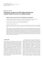
It is known that 3 layers having 2-hidden layers are
better than 2 layers to approximate any given function [14].
However, a 2-layer MLP is used in this paper, as shown in
Figure 1. The output error equation of the first layer (15)
and the error equation of the second layer (21)aredifferent.
However, the error equation of the second layer (21) and the
error equation of the other layers (22) are the same form.
EURASIP Journal on Embedded Systems 3
−3 −2 −10 1 2 3
x
−3
−2
−1
0
1
2
3
f (x)
f (x) =
2
(1 + e
−2x
)
−1
f (x)
= 0.75x
Figure 2: Estimation (5) of an activation function (3).
Multiplication and
accumulation
(MAC)
FPU multiplication
Neural network
top module
FPU addition
(modified from Leon
processor FPU)
FPGA multiplier
(H/W IP)
Figure 3: Block diagram of the neural network in an FPGA.
Therefore, a 2-layer MLP is enough to be examined in this
paper. The number of neurons of 400 and 300 were used for
input and first layer respectively in this experiment.
After the face data enters the input node, it is calcu-
lated by the multiplication-and-accumulation (MAC) with
weights. Face or non-face data is determined by comparing
output results with the thresholds. For example, if the output
is larger than the threshold, it is considered as a face data.
Here, on the FPGA, this decision is easily made by checking a
sign bit after subtracting the output results and the threshold.
2.2. Estimation of Activation Function. An activation func-
tion is used to calculate the output of the neural network.
The learning procedure of the neural network requires
the differentiation of the activation function to renew the
weights value. Therefore, the activation function has to be
differentiable. A sigmoid function, having an “S” shape, is
used for the activation function, and a logistic or a hyperbolic
tangent function is commonly used as the sigmoid function.
The hyperbolic tangent function and its antisymmetric
feature were better than the logistic function for learning
ability in our experiment. Therefore, hyperbolic tangent
sigmoid transfer function was used, as shown in (3). The
first-order derivative of the hyperbolic tangent sigmoid
FPU multiplication
Data
fetch
Stage1
S2 S3 S4 S5
Pre-
norm
Post-
norm
Round/
norm
Adder
Figure 4: Block diagram of 5 stage-pipelined FPU.
Table 1: MRRE and ARRE of Five Different FBUs.
Bit-width
Unit
β, e, m
∗
Range MRRE(ulp) ARRE
FPU32 2, 8, 23 2
2
8
−1
= 2
255
2
−23
0.3607 ×2
−23
FPU24 2, 6, 17 2
−17
0.3607 ×2
−17
FPU20 2, 6, 13 2
−13
0.3607 ×2
−13
FPU16 2, 6, 9 2
2
6
−1
= 2
63
2
−9
0.3607 ×2
−9
FPU12 2, 6, 5 2
−5
0.3607 ×2
−5
∗
β: radix, e:exponent,m:mantisa.
Table 2: Timing results of the neural network-based FPGA face
detector by different FPUs.
Bit-width
Max. Clock
(MHz)
1/f(ns)
Time
∗∗
/1
frame (ms)
Frame rate
∗∗∗
FPU64
∗
8.5
117
50 20
FPU32 48
21.7
8.7 114.4
FPU24 58 (+21%)
17.4
7.4 135.9
FPU20 77 (+60%)
13
5.5 182.1
FPU16 80 (+67%)
12.5
5.3 189.8
FPU12 85 (+77%)
11.7
5 201.8
∗
General PCs use the 64-bit FPU,
∗∗
operating time = [(1 / Max. Clock) ×
423,163 (total cycle)],
∗∗∗
frame rate = 1000/Operating time.
transfer function can be easily obtained as (4). MATLAB
provides the commands, “tansig” and “dtansig”:
f
(
x
)
=
2
(
1+e
−2x
)
−1 =
1 −e
−2x
1+e
−2x
,(3)
f
(
x
)
= 1 − f
(
x
)
2, (4)
where x
=input
j
in (2).
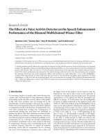
The activation function can be estimated by using
different methods. The Taylor and polynomial methods are
effective, and guarantee the highest speed and accuracy
among these methods.
The polynomial method is used to estimate the activation
function in this paper as seen in (5)and(6) because it is
simpler than the Taylor approximation.
A first-degree polynomial estimation of an activation
function is
f
(
x
)
= 0.75x. (5)
4 EURASIP Journal on Embedded Systems
Pre-
processing
Save
weights
Data
(face and
non-face)
Memory
(weights)
Memory
(input
data)
MATLAB (learning)
MATLAB (detection)
Performace
test and
verification
NN
detector
NN
detector
MODELSIM
(simulation)
Xilinx ISE
(design and synthesis)
NN
learning
program
Pre-
processing
Figure 5: Block diagram of the design environment.
A first-order derivative is
f
(
x
)
= 0.75. (6)
Figure 2 shows the estimation (5)ofanactivationfunc-
tion (3).
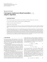
2.3. FPU Implementat ion. Figure 3 shows the simplified
block diagram of the implemented neural network in an
FPGA. The module consists of control logic and an FPU.
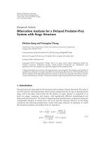
The implemented FPU is IEEE 754 Standard [15]
compliant. The FPU in this system has two modules: mul-
tiplication and addition. Figure 4 shows the block diagram
of the 5 stage-pipelined FP addition and multiplication unit
implemented in this paper. A commercial IP core, an FP
adder of the LEON processor [16] is used and modified to
make the bit size adjustable. A bit-width reduced floating-
point multiplication unit is designed using a multiplier and
ahardintellectualproperty(IP)coreinanFPGAtoimprove
speed. Consequently, the multiplication was performed
within 2 cycles of total stages as shown in Figure 4.
2.4. Implementation of the Neural Network-Based FPGA Face
Detector Using MATLAB and VHDL. Figure 5 shows the total
design flow using MATLAB and VHDL. MATLAB program
consists of two parts: learning and detection. After the
learning procedure, weights data are fixed and saved to a file.
The weights file is saved to a memory model file for FPGA
and VHDL simulation. The MATLAB also provides input test
data to the VHDL program and analyzes the result from the
result file of MODELSIM simulation program. Preprocessing
includes mask, resizing, and normalization.
The Olivetti face database [17] is chosen for this study.
The Olivetti face database consists of mono-color face and
0 50 100 150 200 250
The number of input data
−0.5
0
0.5
1
1.5
Neural network output
(threshold)
Non-face data
(160: #61
∼ #220)
Face data
(60: #1 ∼ #60)
Figure 6: Data classification result of the neural network.
1
2
p
1
2
o
1
2
m
1
2
n
···
···
···
···
···
.
.
.
.
.
.
.
.
.
.
.
.
Node: i
j
kl
Data: X
i
O
j
O
k
O
l
We ig h ts:
W
ij
W
jk
W
kl
Error:
ε
j
ε
k
ε
l
Figure 7: Error model for general neural network.
EURASIP Journal on Embedded Systems 5
01234567
x
0
0.1
0.2
0.3
0.4
0.5
0.6
0.7
0.8
0.9
1
f
(x)
f
(x) = 1 −
2
1+e
−2x
−1
2
−30 −20 −10 0 10 20 30
x
0
0.1
0.2
0.3
0.4
0.5
0.6
0.7
0.8
0.9
1
f
(x)
Figure 8: First derivative graph of the activation function.
Table 3: Area results of the neural network-based FPGA face
detector by different FPUs.
Bit-width No. of Slices No. of FFs No. of LUTs
FPU32 1077 771 1952
FPU24 878 (–18.5%) 637 1577
FPU20 750 (–30.4%) 569 1356
FPU16 650 (–39.7%) 501 1167
FPU12 556 (–48.4%) 433 998
Table 4: Area results of 32/24/20/16/12-Bit FP adders.
FP Adder Bit-
width
Memory (Kbits)
NN
Area (Slices)
FP
Adder area
(Slices)
32 3760 1077 486
24 2820 (
−25%) 878 403 (−17%)
20 2350 (
−37%) 750 300 (−38%)
16 1880 (
−50%) 650 250 (−49%)
12 1410 (
−63%) 556 173 (−64%)
non-face image so it is easy to use. Some other databases
which have large size, color, mixed with other pictures are
difficult for this error analysis purpose due to the necessity
of more preprocessing like cropping, data classification, and
color model change.
Figure 6 shows the classification result of 220 face and
non-face data. X-axis shows the data number of face data
Table 5: Power consumption of the neural network-based FPGA
face detector by the different FPUs (unit: Mw).
Bitwidth
CLBs RAM (Width)
Multiplier
(Block)
I/O Power
∗
FPU32
2 17 ( 36)
9(5)
67 306
FPU24
2 17 ( 36)
7(4)
49 286 (–6.5%)
FPU20
2 17 ( 36)
4(2)
45 279 (–8.8%)
FPU16
2 8 ( 18)
4(2)
36 261 (–14.7%)
FPU12
1 8 ( 18)
4(2)
29 253 (–17.3%)
∗
To t a l p o w e r = sub sum + 211 mW (basic power consumption of the
FPGA)
Table 6: Comparison of different FP adder architectures (5 pipeline
stages).
Adder type Slices FFs LUTs Max. freq. (MHz)
LEON IP 486 269 905 71.5
LOP 570 (+17%) 294 1052 102 (+42.7%)
2-path 1026(+111%) 128 1988 200 (+180%)
Table 7: Specifications of neural network-based FPGA face detector
Feature
Specification
FPU Bit-width
32, 24, 20, 16, 12
Frequency
48/58/77/80/85 MHz
Slices (Xilinx Spartan)
1077/878/750/650/556
(FPU32/FPU16)
Arithmetic unit
IEEE 754 single precision with
bit-width reduced FPU
Networks
2 Layers (400/300/1 node)
Input Data Size
20
×20 (400 pixel image)
Operating Time
8.7/7.4/5.5/5.3/5 ms/frame
Frame Rate
114/136/182/190/201 seconds
from 1 to 60, and non-face data from 61 to 220. Y-axis shows
the output value of the neural network. The neural network
is learned to pursue the desired value “1” for face and “–1”
for non-face.
3. Error Analysis of the Neural Network Caused
by Reduced-Precision FPU
3.1. MRRE and ARRE. ThenumberofbitsintheFPUis
important for the area, operating speed, and power [13].
Therefore, it is important to decide the minimal number
of bits in floating-point hardware to reduce hardware costs,
yet maintain an application’s overall accuracy. A maximum
relative representation error (MRRE) [18]isusedasoneof
the indices of floating-point arithmetic accuracy, as shown
in Tab le 1 . Note that “e”and“m”representexponent and
mantissa, respectively. The MRRE can be obtained as follows:
MRRE
=
1
2
×ulp ×β,(7)
where ulp is a unit in the last position and β is the exponent
base.
6 EURASIP Journal on Embedded Systems
Table 8: Difference between (3) and (5) in face detection rate (MATALAB).
Threshold 0.1 0.2 0.3 0.4 0.5 0.6 0.7 0.8 0.9 10
Tansig (3) 34.09 34.55 37.27 45.91 53.64 61.36 73.09 77.73 75 72.73
Poly (5) 35 39.09 45.91 53.64 62.73 70 72.27 77.27 78.18 77.27
Abs diff 0.91 4.54 8.64 7.73 9.09 8.64 0.82 0.46 3.18 4.54
Avg. error 4.9
Table 9: Detection rate of PC software face detector.
Threshold 0.1 0.2 0.3 0.4 0.5 0.6 0.7 0.8 0.9 1
Face 60 60 60 53 50 43 29 21 17 10
Rate 100 100 100 88.33 83.33 71.67 48.33 35 28.33 16.67
Nface 17 26 41 65 88 111 130 149 155 160
Rate 10.625 16.25 25.625 40.625 55 69.375 81.25 93.125 96.875 100
Total 35 39.09 45.91 53.64 62.73 70 72.27 77.27 78.18 77.27
An average relative representation error (ARRE) can be
considered for practical use:
ARRE
=
β − 1
ln β
×
1
4
×ulp. (8)
3.2. Output Error Estimation of the Neural Network. The FPU
representation error increases with repetitive multiplication
and addition in the neural network. The difference in output
can be expressed using the following equations with the
notation depicted in Figure 7.
The error of the 1st layer is the difference between the
output by a finite precision arithmetic (O
f
j
) and the ideal
output (O
j
), and it can be described as
ε
j
= O
f
j
−O
j
= f
⎛
⎝
n
i=1
W
f
ij
X
f
ij
⎞
⎠
+ ε
Φ
− f
⎛
⎝
n
i=1
W
ij
X
i
⎞
⎠
,
(9)
where ε
j
represents the hidden layer error (ε
k
represents total
error generated between hidden layer and output layer on
Figure 7), W represents the weights, X represents input data,
and O represents the output of the hidden layer. ε
Φ
is the
summation of other possible errors, and defined by
ε
φ
= ε
f
+ Multiplication Error
(
ε
∗
)
+ Summation Error
(
ε
+
)
+ Other Calculation Errors
(10)
ε
f
is the nonlinear function error by Taylor estimation; ε
f
is
very small and negligible. Therefore, ε
f
becomes 0.
Other calculation errors occur when the differential of
activation is calculated (i.e., f
(x) = 0.75 × sum), and the
final face determination is calculated as follows: f(x)
= f
(x)
+(-0.5).
The multiplication error, ε
∗
, is not considered in this
paper. The multiplication unit assigns twice the size of the
bits to save the result data. For example, multiplication of
16 bits
× 16 bits needs 32 bits. This large size register reduces
the error, thus the ε
∗
error is negligible.
However, the summation error, ε
+
is not negligible and
added to the error term, ε
Φ
. The multiplication error (ε
∗
)
and the addition error (ε
+
) are bounded by the MRRE
(assuming rounding mode
= truncation) as given by (11)
and (12):
ε
∗
<
Multiplication Result ×
(
−MRRE
)
, (11)
where negative sign (–) describes the direction.
For example, the ε
∗
of “4 ×5 = 20”:ε
∗
= 20 ×(−MRRE):
ε
+
< |Addition Result ×
(
−MRRE
)
|. (12)
For example, the ε
+
of “4 + 5 = 9”: ε
+
= 9 ×(−MRRE).
Note that the maximum error caused by truncation of
rounding scheme is bounded as
ε
t
<
x ×
−2
−ulp
=|
x ×
(
−MRRE
)
|. (13)
The error caused by round-to-the-nearest scheme is
bounded as
ε
n
<
x ×
2
−ulp−1
=
x ×
1
2
×
(
−MRRE
)
. (14)
The truncation of rounding scheme creates a negative
error and a round-to-nearest scheme creates a positive error.
The total error can be reduced by almost 50% by round-to-
nearest scheme [18].
From (9), the terms W
f
and X
f
are weights data and
input data, respectively, including the reduced-precision
error. They are described by W
f
= W +ε
W
and X
f
= X +ε
X
.
Therefore, the multiplication of weights and input data are
denoted byW
f
X
f
= (W + ε
W
)(X + ε
X
).
Equations (16)and(18) are obtained by applying the
first-order Taylor’s series approximation as given by [7, 8]
f
(
x + h
)
− f
(
x
)
= hf
(
x
)
. (15)
From (9), the error of the first layer, ε
j
,isgivenby
ε
j
= f
⎛
⎝
n
i=1
W
ij
X
i
+ h
1
⎞
⎠
−
f
⎛
⎝
n
i=1
W
ij
X
i
⎞
⎠
+ ε
+
= h
1
× f
⎛
⎝
n
i=1
W
ij
X
i
⎞
⎠
+ ε
+
,
(16)
EURASIP Journal on Embedded Systems 7
Table 10: Detection rate of reduced-precision FPUs (VDHL).
Threshold 0.1 0.2 0.3 0.4 0.5 0.6 0.7 0.8 0.9 1 Avg. detection rate error
FPU64 (PC) 35 39.09 45.91 53.64 62.73 70 72.27 77.27 78.18 77.27
FPU32 NN 35 39.09 45.91 53.64 62.73 70 72.27 76.82 78.18 77.27 0
FPU24 NN 35 39.09 45.91 53.64 62.73 70 72.27 76.82 78.18 77.27 0
FPU20 NN 35 39.09 46.36 53.64 63.18 70 73.64 76.82 77.73 76.82 0.36
FPU18 NN 35 41.36 47.73 56.82 65.46 69.55 74.55 77.73 77.27 74.09 1.73
FPU16 NN 35.91 44.55 53.18 66.36 70.46 76.36 78.18 74.55 72.73 72.73 5.91
|FPU64-FPU16| 0.91 5.45 7.27 12.73 7.73 6.36 5.91 2.73 5.46 4.55 5.91
where
h
1
=
n
i=1
ε
Xi
X
i
+ ε
Wij
W
ij
+ ε
Wij
ε
Xi
. (17)
The error of the second layer can also be found as
ε
k
= O
f
k
−O
k
= f
⎛
⎝
m
j=1
O
f
j
W
f
jk
⎞
⎠
−
f
⎛
⎝
m
j=1
O
j
W
jk
⎞
⎠
+ ε
+
.
(18)
By replacing the O
f
j
and the W
f
jk
with (O
j
+ε
j
) and(W
jk
+
ε
Wjk
), (18)becomes
ε
k
= f
⎛
⎝
m
j=1
O
j
+ ε
j
W
jk
+ ε
Wjk
⎞
⎠
−
f
⎛
⎝
m
j=1
O
j
W
jk
⎞
⎠
+ ε
+
.
(19)
Simply,
ε
k
= f
⎛
⎝
m
j=1
O
j
W
jk
+ h
2
⎞
⎠
−
f
⎛
⎝
m
j=1
O
j
W
jk
⎞
⎠
+ ε
+
≈ h
2
× f
⎛
⎝
m
j=1
O
j
W
jk
⎞
⎠
+ ε
+
,
(20)
where
h
2
=
m
j=1
ε
Wjk
O
j
+ ε
j
W
jk
+ ε
Wjk
ε
j
. (21)
ε
k
≈
⎛
⎝
m
j=1
ε
Wjk
O
j
+ ε
j
W
jk
⎞
⎠
f
⎛
⎝
m
j=1
O
j
W
jk
⎞
⎠
+ ε
+
.
(22)
The error (22) can be generalized for the lth layer, l,ina
similar way:
ε
l
≈
⎛
⎝
o
k=1
(
ε
Wkl
O
k
+ ε
k
W
kl
)
⎞
⎠
f
⎛
⎝
o
k=1
O
k
W
kl
⎞
⎠
+ ε
+
. (23)
3.3. Output Error Estimation by MRRE and ARRE. The error
equation can be rewritten using the MRRE in the error
term to find the maximum output error caused by reduced-
precision. The average error can be estimated in the practical
application by replacing the MRRE with ARRE
= (0.3607 ×
MRRE).
From (16), the output error of the first layer is described
as
ε
j
≈
⎛
⎝
n
i=1
(
ε
W
X + ε
X
W
)
⎞
⎠
f
⎛
⎝
n
i=1
W
ij
X
i
⎞
⎠
+ ε
+
. (24)
The ε
W
(max)and ε
X
(max)terms can be defined by
ε
W
(max) = W ×−MRRE and ε
X
(max) = X ×−MRRE.
Thus from (24), the error ε
j
is bounded so that
ε
j
<
⎛
⎝
n
i=1
W
ij
×−MRRE
×
X
i
(
X
i
×−MRRE
)
×W
ij
⎞
⎠
×
f
⎛
⎝
n
i=1
W
ij
X
i
⎞
⎠
+ ε
+
;
(25)
ε
j
<
−
2MRRE
⎛
⎝
n
i−1
W
ij
X
i
⎞
⎠
f
⎛
⎝
n
i=1
W
ij
X
i
⎞
⎠
+ ε
+
, (26)
where
ε
+
≈
n
i=1
X
i
W
ij
×−
MRRE. (27)
Finally, the output error of the second layer ε
k
is also
described from (22) as shown in (28), where the error of
weights can also be written as
ε
Wjk
(
max
)
=
W
jk
×−MRRE
,
ε
k
<
⎛
⎝
m
j=1
W
jk
×−MRRE ×O
j
+
ε
j
×W
jk
⎞
⎠
×
f
⎛
⎝
m
j=1
O
j
W
jk
⎞
⎠
+ ε
+
,
(28)
where
ε
+
≈
n
i=1
O
j
W
jk
×−
MRRE. (29)
8 EURASIP Journal on Embedded Systems
Table 11: Results of output error on a neural network-based FPGA
face detector.
Bit-width
Calculation Experiment
MRRE ARRE max
FPU32 4E-05 2.89E-05 1.93E-05
FPU24 0.0026 0.0018 0.0012
FPU20 0.0410 0.0296 0.0192
FPU18 0.1641 0.1184 0.0766
FPU16 0.6560 0.4733 0.2816
FPU14 2.62 1.891 0.9872
FPU12 10.4 7.5256 1.0741
3.4. Relationship between MRRE and Output Error. In order
to observe the relationship between the MRRE and output
error, (28) is written as (30) again.
By using (26),
ε
k
<
−
MRRE ×A × f
⎛
⎝
m
j=1
O
j
W
jk
⎞
⎠
+ ε
+
, (30)
where
A
=
m
j=1
W
jk
×O
j
+
⎛
⎝
2 ×
⎛
⎝
n
i=1
W
ij
X
i
⎞
⎠
×
f
⎛
⎝
n
i=1
W
ij
X
i
⎞
⎠
×
W
jk
⎞
⎠
⎤
⎦
.
(31)
Some properties are derived from (26)and(30)for
the output error. The differential of summations affects the
output error proportionally like
ε
j
∝ f
⎛
⎝
n
i=1
W
ij
X
i
⎞
⎠
,from
(
24
)
,
ε
k
∝ f
⎛
⎝
m
j=1
O
j
W
jk
⎞
⎠
,from
(
26
)
.
(32)
The output of the well-learned neural network system
goes to the desired value as shown in Figure 2. In that case,
the differential value goes to 0 as shown in Figure 8.Itmeans
the well-learned neural network system has less output error.
One more finding is that the output error is also
proportional to the MRRE.
From the (30),
ε
k
∝ MRRE, (33)
where MRRE
= 2 − ulp (assuming “rounding mode =
truncation”). Therefore, (33) can be described as
ε
k
∝ 2
−ulp
. (34)
Finally, it is concluded that n-bits reduction in the FPU
creates 2
n
times the error. If one bit is reduced, for example,
4 times
12 14 16 18 20 22 24 26 28 30 32
FPU bits
0
2
4
6
8
10
12
Output errors
Calculation (MRRE)
Calculation (ARRE)
Experiment (max)
Experiment (mean)
Figure 9: Comparison between analytical output errors and
experimental output errors.
2
12 14 16 18 20 22 24 26 28 30 32
FPU bits
−20
−18
−16
−14
−12
−10
−8
−6
−4
−2
0
2
4
Output errors (log 2)
Calculation (MRRE)
Calculation (ARRE)
Experiment (max)
Experiment (mean)
Figure 10: Comparison between analytical output errors and
experimental output errors (log
2
).
the output error is doubled (e.g., 2
−(−1)
= 2). After putting
the MRRE between FPU32 and other reduced precision FPU
bits into error terms in (26)and(28) using MATLAB and real
face data, finally, the total accumulated error of the neural
network is obtained as shown in Ta bl e 11 .
4. Result and Discussion
4.1. FPGA Synthesis Results. The FPGA-based face detector
using the neural network and the reduced-precision, FPU, is
implemented in this paper. The logic circuits of the neural
network-based FPGA face detector are synthesized using the
FPGA design tool, Xilinx ISE on a Spartan-3 XC3S4000 [19].
To verify the error model, first of all, the neural network on
a PC is designed using MATLAB. Next, the weights and test-
bench data are saved as a file to verify the VHDL code.
After simulation, area and operating speed are obtained
by synthesizing the logic circuits. The FPU uses the same
calculation method, floating-point arithmetic, as the PC so
it is easy to verify and easy to change the neural network’s
structure.
EURASIP Journal on Embedded Systems 9
4.1.1. Timing. The implemented neural network-based
FPGA face detector (FPU16) took only 5.3 milliseconds to
process 1 frame at 80 MHz which is 9 times faster than
50 milliseconds (i.e., 40 milliseconds for loading time +
10 milliseconds for calculation time) required for a PC
(Pentium 4, 1.4 GHz) as shown in Ta bl e 2. As the total FPU
representation bits decrease, a maximum clock frequency
increases considerably from 21% (FPU24) to 67% (FPU16)
compared to FPU32.
The remaining question is to examine if bit-width
reduced FPU can still maintain a face detector’s overall
accuracy. For this purpose, detection rate error for bit-width
reduced FPU will be discussed in Section 4.2.2.
4.1.2. Area. As shown in Ta bl e 3, only 2% (650/27648)
and 4% (1077/27648) of the total available slices (3S4000)
are used for FPU16 and FPU32, respectively. Therefore,
the stand-alone embedded face detection system including
preprocessing, FPU, and other extra functions can be easily
implemented on a small inexpensive FPGA.
As the bit-width decreases, the number of slices is
decreased from 18.5% (FPU24) to 39.7% (FPU16) compared
to FPU32.
Bit reduction of the FP adder leads to an area reduction
and a faster operating clock speed. For example, a 50% bit
reduction from FP adder 32 to FP adder 16 results in a 49%
reduction of the adder area (250/486) and a 50% reduction
of the memory (1880/3760) as shown in Tab l e 4. It is possible
to use the XILINX FPGA 3S4000 which provides the size
of 2160 Kbits memory (block RAM: 1728 Kb, distributed
memory: 432 Kb) when the FPU16 is necessary.
The number of slices of the floating-point adder varies
from 31% (FP12: 173/556) to 45% (FP32: 486/1077) of the
total size of the neural network as shown in Ta bl e 4 .
4.1.3. Power. The results of power consumption are shown in
Ta bl e 5. The power consumptions are obtained using Xilinx
Web Pow er Too l [20].
As the bit-width decreases, the power consumption
decreases. For example, bit reduction from the FPU32 to the
FPU16 reduces the total power by 14.7% (FPU32: 306 mW,
FPU16: 261 mW) through RAM, multiplier, and I/O as
shown in Ta bl e 5.
The change of the logic cell does not considerably affect
the power as much as hardwired IP such as memory and
multiplier spend the power. See the number of configurable
logic blocks (CLBs) in Table 5 .
4.1.4. Architectures of FP Adder. The neural network system
and the FPU hardware performance are greatly affected by
the FP addition [21]. The bit-width reduced FP addition
is modified for this study from the commercial IP, LEON
processor. LEON FPU uses standard adder architecture [16].
The system performance and the clock speed can be further
improved by leading-one-prediction (LOP) algorithm and 2-
path (close-and-far path) algorithm, respectively [18].
In our experiment, FP addition based on the LOP
algorithm increases the maximum clock frequency by 42.7%
compared to the performance of the commercial IP, LEON.
The FP addition based on the 2-path algorithm [18, 22]
increases the area by 111%, but improves the maximum
clock frequency by 180% compared to the performance of
the commercial IP, LEON as shown in Ta bl e 6 .
4.1.5. Specification. The specification of the implemented
neural network-based FPGA face detector is summarized in
Ta bl e 7.
4.2. D etection Rate Error. Two f ac to rs affect the detection
rate error. One is the polynomial estimation error as shown
in Figure 2 which is occurred when the activation function
is estimated through the polynomial equation. Another
possible error caused by the bit-width reduced FPU.
4.2.1. Detection R ate Error by Polynomial Estimation. To
reduce the error caused by polynomial estimation, the
polynomial equation, (35) can be more elaborately modified
as shown in (36). The problem of (36)isnotdifferentiable
at
±1, and also the error (30) will be identically 0 (i.e.,
f
(sum) = (±1)
= 0) for|sum| > 1, which will make error
analysis difficult:
f
(
sum
)
= 0.75 ×sum
f
(
sum
)
= 0.75 ×sum, |sum| < 1,
(35)
= 1, sum ≥ 1,
=−1, sum ≤−1.
(36)
Therefore, the simplified polynomial (35) is used in this
paper. It is confirmed through MATLAB simulation that this
polynomial approximation results in an average 4.9% error
in the detection rate compared with the result of (3)inour
experiment as shown in Ta bl e 8.
4.2.2. Detection Rate Error by Reduced-Precision FPU. Tab le 9
is obtained after the threshold value changed from 0.1 to 1.
When the threshold is 0.5, the face detection rate is 83% and
the non-face detection rate is 55%. When the threshold is 0.6,
face and the non-face detect is almost same as 71.67% and
69.4% respectively. As the threshold value goes to “1” (i.e. as
the horizontal red line goes up in Figure 6), face detection
rate is decreased. It means input image is difficult to pass,
and it is good for security. Therefore, the threshold is needed
to be chosen accordingly depending upon applications. The
result of Ta bl e 9 is used in the second column (FPU64(PC))
of the Ta bl e 10 .
Ta bl e 10 shows the detection rate error (i.e.,
|detection
rate of FPU64 (PC software)—detection rate of reduced-
precision FPUs
|) caused by reduced-precision FPUs. The
detection rate is changed from FPU64(PC) to FPU16 by only
5.91% (i.e.,
|72.27 −78.18|).
Ta bl e 11 and Figure 9 show the output error (
|neural
network output on PC- the output of VHDL
|). Figure 10 is
the log graph (base is 2) of Figure 9.
Analytical results are found to be in agreement with
simulation results as shown in Figure 10. The analytical
MRRE results and the maximum experimental results show
10 EURASIP Journal on Embedded Systems
conformity of shape. The analytical ARRE results and the
minimum experimental results also show conformity of
shape.
As the n bits in the FPU are reduced within the ranges
from 32 bits to 14 bits, the output error is incremented by 2
n
times. For example, 2-bit reduction from FPU16 to FPU14
makes 4 times (2
n=16−14=2
= 4) the error.
Due to the small number of fraction bits (e.g., 5 bits
in FPU12), no meaningful results are obtained under 14
bits. Therefore, at least 14 bits should be employed to
achieve an acceptable face detection rate. See Figures 9
and 10.
5. Conclusion
In this paper, the analytical error model was developed
using the maximum relative representation error (MRRE)
and average relative representation error (ARRE) to obtain
the maximum and average output errors for the bit-width
reduced FPUs.
After the development of the analytical error model,
the bit-width reduced FPUs, and the neural network were
designed using MATLAB and VHDL. Finally, the analytical
(MATLAB) results with the experimental (VHDL) results
were compared.
The analytical results and the experimental results
showed conformity of shape. According to both results, as
the n bits in FPU are reduced within the ranges from 32 bits
to 14 bits, the output error is incremented by 2
n
times.
An operating speed was significantly improved from an
FPGA-based face detector implementation using a reduced
precision FPU. For example, it took only 5.3 milliseconds
in the FPU16 to process one frame which is 9 times faster
than 50 milliseconds (40 milliseconds for loading time +10
milliseconds for calculation time) of the PC (Pentium 4,
1.4 GHz). It was found that bit reduction from FPU 32 bits
to FPU16 bits reduced the size of memory and arithmetic
units by 50% and the total power consumption by 14.7%,
while still maintaining 94.1% face detection accuracy. The
developed error analysis for bit-width reduced FPUs will
be helpful to determine the specification for an embedded
neural network hardware system.
Acknowledgments
The authors would like to acknowledge the Natural Science
and Engineering Research Council of Canada (NSERC) / the
University of Saskatchewan’s Publications Fund, the Korea
Research Foundation, and a Korean Federation of Science
and Technology Societies grant funded by the South Korean
government (MOEHRD, Basic Research Promotion Fund)
for supporting this research and to thank the reviewers for
their valuable suggestions.
References
[1] M. Skrbek, “Fast neural network implementation,” Neural
Network World, vol. 9, no. 5, pp. 375–391, 1999.
[2] D. E. Rumelhart and J. L. McClelland, Parallel Distributed
Processing: Explorations in the Microstructure of Cognition, vol.
1, MIT Press, Cambridge, Mass, USA, 1986.
[3] X. Li, M. Moussa, and S. Areibi, “Arithmetic formats for
implementing artificial neural networks on FPGAs,” Canadian
Journal of Electrical and Computer Engineering,vol.31,no.1,
pp. 30–40, 2006.
[4]H.K.Brown,D.D.Cross,andA.G.Whittaker,“Neural
network number systems,” in Proceedings of International Joint
Conference on Neural Networks (IJCNN ’90), vol. 3, pp. 903–
908, San Diego, Calif, USA, June 1990.
[5] J. Kontro, K. Kalliojarvi, and Y. Neuvo, “Use of short floating-
point formats in audio applications,” IEEE Transactions on
Consumer Electronics, vol. 38, no. 3, pp. 200–207, 1992.
[6] J. Tong, D. Nagle, and R. Rutenbar, “Reducing power by
optimizing the necessary precision/range of floating-point
arithmetic,” IEEE Transactions on VLSI Systems,vol.8,no.3,
pp. 273–286, 2000.
[7] J. L. Holt and J N. Hwang, “Finite precision error analysis
of neural network hardware implementations,” IEEE Transac-
tions on Computers, vol. 42, no. 3, pp. 281–290, 1993.
[8] S. Sen, W. Robertson, and W. J. Phillips, “The effects of
reduced precision bit lengths on feed forward neural networks
for speech recognition,” in Proceedings of IEEE International
Conference on Neural Networks, vol. 4, pp. 1986–1991, Wash-
ington, DC, USA, June 1996.
[9] R. Feraud, O. J. Bernier, J E. Viallet, and M. Collobert, “A fast
and accurate face detector based on neural networks,” IEEE
Transactions on Pattern Analysis and Machine Intelligence, vol.
23, no. 1, pp. 42–53, 2001.
[10] H. A. Rowley, S. Baluja, and T. Kanade, “Neural network-
based face detection,” IEEE Transactions on Pattern Analysis
and Machine Intelligence, vol. 20, no. 1, pp. 23–38, 1998.
[11] T. Theocharides, G. Link, N. Vijaykrishnan, M. J. Irwin, and
W. Wolf, “Embedded hardware face detection,” in Proceedings
of the 17th IEEE International Conference on VLSI Design,pp.
133–138, Mumbai, India, January 2004.
[12] M. Sadri, N. Shams, M. Rahmaty, et al., “An FPGA based fast
face detector,” in Global Signal Processing Expo and Conference
(GSPX ’04), Santa Clara, Calif, USA, September 2004.
[13] Y. Lee and S B. Ko, “FPGA implementation of a face detector
using neural networks,” in Canadian Conference on Electrical
and Computer Engineering (CCECE ’07), pp. 1914–1917,
Ottawa, Canada, May 2006.
[14] D. Chester, “Why two hidden layers are better than one,”
in Proceedings of International Joint Conference on Neural
Networks (IJCNN ’90), vol. 1, pp. 265–268, Washington, DC,
USA, January 1990.
[15] IEEE Std 754-1985, “IEEE standard for binary floating-point
arithmetic,” Standards Committee of the IEEE Computer
Society, New York, NY, USA, August 1985.
[16] LEON Processor, .
[17] Olivetti & Oracle Research Laboratory, The Olivetti & Oracle
Research Laboratory Face Database of Faces,
/>[18] I. Koren, Computer Arithmetic Algorithms,AKPeters,Natick,
Mass, USA, 2nd edition, 2001.
[19] XILINX, “Spartan-3 FPGA Family Complete Data Sheet,”
Product Specification, April 2008.
[20] XILINX Spartan-3 Web Power Tool Version 8.1.01, http://
www.xilinx.com/cgi-bin/power
tool/power Spartan3.
[21] G. Govindu, L. Zhuo, S. Choi, and V. Prasanna, “Analysis
of high-performance floating-point arithmetic on FPGAs,” in
EURASIP Journal on Embedded Systems 11
Proceedings of the 18th International Parallel and Dist ributed
Processing Symposium (IPDPS ’04), pp. 149–156, Santa Fe,
NM, USA, April 2004.
[22] A. Malik, Design trade-off analysis of floating-point adder in
FPGAs, M.S. thesis, Department of Electrical and Computer
Engineering, University of Saskatchewan, Saskatoon, Canada,
2005.