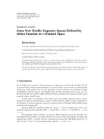
báo cáo hóa học:" Research Article Very Low-Memory Wavelet Compression Architecture Using Strip-Based Processing for Implementation in Wireless Sensor Networks" potx
Bạn đang xem bản rút gọn của tài liệu. Xem và tải ngay bản đầy đủ của tài liệu tại đây (1.13 MB, 16 trang )
Hindawi Publishing Corporation
EURASIP Journal on Embedded Systems
Volume 2009, Article ID 479281, 16 pages
doi:10.1155/2009/479281
Research Article
Very Low-Memory Wavelet Compression Architecture
Using Strip-Based Processing for Implementation in
Wireless Sensor Networks
Li Wern Chew, Wai Chong Chia, Li-minn Ang, and Kah Phooi Seng
Department of Electrical and Electronic Engineering, The University of Nottingham, 43500 Selangor, Malaysia
Correspondence should be addressed to Li Wern Chew,
Received 4 March 2009; Accepted 9 September 2009
Recommended by Bertrand Granado
This paper presents a very low-memory wavelet compression architecture for implementation in severely constrained hardware
environments such as wireless sensor networks (WSNs). The approach employs a strip-based processing technique where an image
is partitioned into strips and each strip is encoded separately. To further reduce the memory requirements, the wavelet compression
uses a modified set-partitioning in hierarchical trees (SPIHT) algorithm based on a degree-0 zerotree coding scheme to give high
compression performance without the need for adaptive arithmetic coding which would require additional storage for multiple
coding tables. A new one-dimension (1D) addressing method is proposed to store the wavelet coefficients into the strip buffer for
ease of coding. A softcore microprocessor-based hardware implementation on a fieldprogrammable gate array (FPGA) is presented
for verifying the strip-based wavelet compression architecture and software simulations are presented to verify the performance of
the degree-0 zerotree coding scheme.
Copyright © 2009 Li Wern Chew et al. This is an open access article distributed under the Creative Commons Attribution License,
which permits unrestricted use, distribution, and reproduction in any medium, provided the original work is properly cited.
1. Introduction
The capability of having multiple sensing devices to commu-
nicate over a wireless channel and to perform data processing
and computation at the sensor nodes has brought wireless
sensor networks (WSNs) into a wide range of applications
such as environmental monitoring, habitat studies, object
tracking, video surveillance, satellite imaging, as well as for
military applications [1–4]. For applications such as object
tracking and video surveillance, it is desirable to compress
image data captured by the sensor nodes before transmission
because of limitations in power supply, memory storage,
and transmission bandwidth in the WSN [1, 2]. For image
compression in WSNs, it is desirable to maintain a high-
compression ratio while at the same time, providing a low
memory and low-complexity implementation of the image
coder.
Among the many image compression algorithms, wave-
let-based image compression based on set-partitioning in
hierarchical trees (SPIHT) [5]isapowerful,efficient, and
yet computationally simple image compression algorithm. It
provides a better performance than the embedded zerotrees
wavelet (EZW) algorithm [6]. Although the embedded block
coding with optimized truncation (EBCOT) algorithm [7]
which was adopted in the Joint Photographic Experts Group
2000 (JPEG 2000) standard provides a higher compression
efficiency as compared to SPIHT, its multilayer coding
procedures are very complex and computationally intensive.
Also, the need for multiple coding tables for adaptive
arithmetic coding requires extra memory allocation which
makes the hardware implementation of the coder more
complex and expensive [7–9]. Thus, from the viewpoint of
hardware implementation, SPIHT is preferred over EBCOT
coding.
In the traditional SPIHT coding, a full wavelet-trans-
formed image has to be stored because all the zerotrees
are scanned in each pass for different magnitude intervals
during the set-partitioning operation [5, 10]. The memory
needed to store these wavelet coefficients increases as the
image resolution increases. This in turn increases the cost of
hardware image coders as a large internal or external memory
bank is needed. This issue is also faced in the implementation
2 EURASIP Journal on Embedded Systems
of on-board satellite image coders where the available
memory space is limited due to power constraints [11].
By adopting the modifications in the implementation
of the discrete wavelet transform (DWT) where the wavelet
transformation can be carried out without the need for full
image transformation [12], SPIHT image coding can also
be performed on a portion of the wavelet subbands. The
strip-based image coding technique proposed in [10]which
sequentially performs SPIHT coding on a portion of an
image has contributed to significant improvements in low-
memory implementations for image compression. In strip-
based coding, a few image lines that are acquired in raster
scan format are first wavelet transformed. The computed
wavelet coefficients are then stored in a strip-buffer for
SPIHT coding. At the end of the image coding, the strip-
buffer is released and is ready for the next set of data lines.
In this paper, a hardware architecture for strip-based
image compression using the SPIHT algorithm is presented.
The lifting-based 5/3 DWT which supports a lossless
transformation is used in our proposed work. The wavelet
coefficients output from the DWT module is stored in
a strip-buffer in a predefined location using a new one-
dimension (1D) addressing method for SPIHT coding. In
addition, a proposed modification on the traditional SPIHT
algorithm is also presented. In order to improve the coding
performance, a degree-0 zerotree coding methodology is
applied during the implementation of SPIHT coding. To
facilitate the hardware implementation, the proposed SPIHT
coding eliminates the use of lists in its set-partitioning
approach and is implemented in two passes. The proposed
modification reduces both the memory requirement and
complexity of the hardware coder. Besides this, the fast
zerotree identifying technique proposed by [13] is also
incorporated in our proposed work. Since the recursion of
descendant information checking is no longer needed here,
the processing time of SPIHT coding significantly reduced.
The remaining sections of this paper are organized as fol-
lows. Section 2 presents an overview of the strip-based cod-
ing followed by a discussion on the lifting-based 5/3 DWT
and its hardware implementation in Section 3. Section 4
presents the proposed 1D addressing method for DWT
coefficients in a strip-buffer and new spatial orientation tree
structures which is incorporated into our proposed strip-
based coding. Next, a proposal on modifications to the tra-
ditional SPIHT coding to improve its compression efficiency
and the hardware implementation of the proposed algorithm
in strip-based coding are presented in Section 5.Thepro-
posed work is implemented using our designed microproces-
sor without interlocked pipeline stages (MIPS) processor on
a Xilinx Spartan III field programmable gate array (FPGA)
device and the results of software simulations are discussed
in Section 6. Finally, Section 7 concludes this paper.
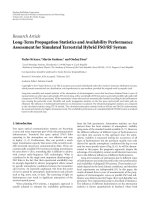
2. Strip-Based Image Coding
Traditional wavelet-based image compression techniques
first apply a DWT on a full resolution image. The computed
N-scale decomposition wavelet coefficients that provide a
Wave le t coe fficients in a strip buffer
Wavelet transform of a full image
SPIHT coding
Figure 1: SPIHT coding is carried out on part of the wavelet
coefficients that are stored in the strip buffer.
compact multiresolution representation of the image are
then obtained and stored in a memory bank. Entropy coding
is subsequently carried out to achieve compression. This
type of coding technique that requires the whole image to
be stored in a memory is not suitable for processing large
images especially in a hardware constrained environment
where limited amount of memory is available.
A low-memory wavelet transform that computes the
wavelet subband coefficients on a line-based basis has
been proposed in [12]. This method reduces the amount
of memory required for the wavelet transform process.
While the wavelet transformation of the image data can
be processed in a line-based manner, the computed full
resolution wavelet coefficients still have to be stored for
SPIHT coding because all the zerotrees are scanned in each
pass for different magnitude intervals [5, 10].
The strip-based coding technique proposed in [10]which
adopts the line-based wavelet-transform [12]hasresulted
in great improvements in low-memory implementations for
SPIHT compression. In strip-based coding, SPIHT coding is
sequentiallyperformedonafewlinesofwaveletcoefficients
that are stored in a strip buffer as shown in Figure 1.Once
the coding is done for a strip buffer, it is released and is
then ready for the next set of data lines. Since only a portion
of the full wavelet decomposition subband is encoded at a
time, there is no need to wait for the full transformation
of the image. Coding can be performed once a strip is fully
buffered. This enables the coding to be carried out rapidly
and also significantly reduces the memory storage needed for
the SPIHT coding.
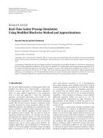
Figure 2 shows the block diagram of the strip-based
image compression that is presented in this paper. A few
lines of image data are first loaded into the DWT module
(DWT
MODULE) for wavelet transformation. The wavelet
coefficients are computed and then stored in a strip-buffer
(STRIP
BUFFER) for SPIHT encoding (SPIHT ENCODE).
At the end of encoding, the bit-stream generated is trans-
mitted as the output. In the next few sections, the detailed
function and the hardware architecture of each of these
blocks will be presented.
3. Discrete Wavelet Transform
The DWT is the mathematical core of the wavelet-based
image compression scheme. Traditional two-dimension (2D)
EURASIP Journal on Embedded Systems 3
DWT MODULE
(Original image)
Image strip
512
512
16
16
× 512
STRIP
BUFFER
SPIHT ENCODE Bit-stream
Figure 2: Block diagram of proposed strip-based image compression.
HHLH
LL HL
LL
3
HL
3
LH
3
HH
3
HL
2
LH
2
HH
2
HL
1
LH
1
HH
1
Two-scale decomposition is carried
out on LL subband
One-scale DWT decomposition
(a)
Three-scale DWT decomposition
(b)
Figure 3: 2D wavelet decomposition.
DWT first performs row filtering on an image followed by
column filtering. This gives rise to four wavelet subband
decompositions as shown in Figure 3(a). The Low-Low (LL)
subband contains the low-frequency content of an image in
both the horizontal and the vertical dimension. The High-
Low (HL) subband contains the high-frequency content of
an image in the horizontal and low-frequency content of
an image in the vertical dimension. The Low-High (LH)
subband contains the low-frequency content of an image
in the horizontal and high-frequency content of an image
in the vertical dimension, and finally, the High-High (HH)
subband contains the high-frequency content of an image in
both the horizontal and the vertical dimension.
Each of the wavelet coefficients in the LL, HL, LH,
and HH subbands represents a spatial area corresponding
to approximately a 2
× 2 area of the original image [6].
For an N-scale DWT decomposition, the coarsest subband
LL is further decomposed. Figure 3(b) shows the subbands
obtained for a three-scale wavelet decomposition. As a result,
each coefficient in the coarser scale represents a larger spatial
area of the image but a narrower band of frequency [6].
The two approaches that are used to perform the DWT
are the convolutional based filter bank method and the lifting
based filtering method. Between the two methods, the lifting
based DWT is preferred over the convolutional based DWT
for hardware implementation due to its simple and fast
lifting process. Besides this, it also requires a less complicated
inverse wavelet transform [14–18].
3.1. Lifting Based 5/3 DWT. ThereversibleLeGall5/3filter
is selected in our proposed work since it provides a lossless
transformation. In the implementation of lifting-based 5/3
DWT [18–20], three computation operations—addition,
subtraction, and shift—are needed. As shown in Figure 4,
the lifting process is built based on the split, prediction, and
updating steps. The input sequence X[n] is first split into odd
and even components for the horizontal filtering process. In
the prediction phase, a high-pass filtering is applied to the
input signal which results in the generation of the detailed
coefficient H[n]. In the updating phase, a low-pass filtering
is applied to the input signal which leads to the generation of
the approximation coefficient L[n]. Likewise, for the vertical
filtering, the split, prediction, and updating processes are
repeated for both the H[n]andL[n]coefficients. Equations
(1)and(2) give the lifting implementation of the 5/3 DWT
filter used in JPEG 2000 [19]:
H
[
2n +1
]
= X
[
2n +1
]
−
X
[
2n
]
+ X
[
2n +2
]
2
,
(1)
L
[
2n
]
= X
[
2n
]
+
H
[
2n − 1
]
+ H
[
2n +1
]
+2
4
.
(2)
4 EURASIP Journal on Embedded Systems
+
+
Split
Odd
Even
Split
Odd
Even
Split
Predict Update
Odd
Even
Row filtering
Column filtering
Predict
Predict
Update
HH
LH
HL
LL
Update
+
−
−
−
H
L
X[n]
X[2n +1]
X[2n]
X[2n +2]
Subtractor
−
Adder
+
Shifter
>> 1
H[2n +1]
X[2n]
H[2n
− 1]
H[2n +1]
Shifter
>> 2
Adder
+
Adder
+2
Adder
+
L[2n]
Figure 4: Implementation of the lifting-based 5/3 DWT filter: Prediction, highpass filtering, and Updating, lowpass filtering.
TEMP_BUFFER
DWT_MODULE
HPF
(ODD)
Row filtering
LPF
(EVEN)
HPF
(ODD)
LPF
(EVEN)
Col. filtering
Image pixel
DWT coefficients
New address calculating unit
Original pixel
location
Pixel location in
STRIP_BUFFER
STRIP_BUFFER
HH2
HH1
HL1
LH1
HL2
LH2
LLn
.
.
.
Figure 5: Architecture for DWT MODULE.
3.2. Architecture for DWT MODULE. In our proposed work,
a four-scale DWT decomposition is applied on an image size
of 512
× 512 pixels. For a four-scale DWT decomposition,
the number of lines that is generated at the first scale
when one line is generated in the fourth scale is equal to
eight. This means that the lowest-memory requirement that
we can achieve at each subband with a four-scale wavelet
decomposition is eight lines. Since each wavelet coefficient
represents a spatial area corresponding to approximately a 2
× 2 area of the original image, the number of image rows that
needs to be fed into the DWT
MODULE is equal to 16 lines.
Equation (3) shows the relationship between the number of
image rows that are needed for strip-based coding, R
image
and
the level of DWT decomposition to be performed, N:
R
image
= 2
N
. (3)
Figure 5 shows our proposed architecture for the
DWT
MODULE. In the initial stage (where N = 1),
image data are read into the DWT
MODULE in a row-by-
row order from an external memory where the image data
are kept. Row filtering is then performed on the image row
and the filtered coefficients are stored in a temporary buffer
(TEMP
BUFFER). As soon as four lines of row-filtered
coefficients are available, column filtering is then carried
out. The size of TEMP
BUFFER is four lines multiplied by
the width of the image. The filtered DWT coefficients HH,
HL, LH, and LL are then stored in the STRIP
BUFFER.
For an N-scale DWT decomposition where N>1, LL
coefficients that are generated in stage (N
− 1) are loaded
from the STRIP
BUFFER back into the TEMP BUFFER. A
N-scale DWT decomposition is then performed on these
LL coefficients. Similarly, the DWT coefficients generated in
EURASIP Journal on Embedded Systems 5
Full image
H[15] = X[15] − [(X[14] + X[16])/2]
Image line
X[0]
X[14]
X[15]
X[16]
(a)
Strip
image 1
H[15] = X[15] − [(X[14] + X[14])/2]
Image line
X[0]
X[14]
X[15]
X[14]
Symmetric
extension
using reflection
(b)
Figure 6: Symmetric extension in strip-based coding.
the N-level are then stored back into the STRIP BUFFER.
The location of each wavelet coefficient to be stored in the
STRIP
BUFFER is provided by the new address calculation
unit and will be discussed in Section 4.
3.3. Symme tric Extension in Strip-Based Coding. From (1)
and (2), it can be seen that to calculate the wavelet
coefficient (2n + 1), wavelet coefficients (2n)and(2n +2)
are also needed. For example, to perform column filtering
at image row 15, image rows 14 and 16 are needed as
shown in Figure 6(a). However, in our proposed strip-based
coding, only a strip image of size 16 rows is available at a
time. Thus, during the implementation of the strip-based
5/3 transformation, a symmetric extension using reflection
method is applied at the edges of the strip image data as
shown in Figure 6(b). Compared to the traditional 2D DWT
which performs wavelet transformation on a full image,
the wavelet coefficientoutputfromtheDWT
MODULE
is expected to be slightly different due to the symmetric
extension carried out. Analysis from our study shows that the
percentage error in wavelet coefficient value is not significant
since only an average of 0.81% differences is observed.
It should be noted that the strip-based filtering can also
support the traditional full DWT if the number of image lines
for strip-based filtering is increased from 16 lines to 24 lines.
This is because each wavelet coefficient at N-scale would
require one extra line of wavelet coefficients at N
− 1scale
for the 5/3 DWT. Thus, for a four-scale DWT, a total of eight
additional image lines are required. This approach is applied
in the strip-based coding proposed in [10] which uses the
line-based DWT implementation proposed in [12]. However,
in order to achieve the low memory implementation of image
coder, our proposed work described in this paper applies the
reflection method for its symmetric extension in the DWT
implementation.
4. Architecture for STRIP BUFFER
The wavelet coefficients generated from the DWT MODULE
are stored in the STRIP
BUFFER for SPIHT coding. The
number of memory lines needed in STRIP
BUFFER is equal
to two times the lowest-memory requirement that we can
achieve at each subband. Therefore, the size of the strip-
buffer is equal to the number of image rows needed for strip-
based coding multiplied by the number of pixels in each row.
Equation (4) gives the size of a strip-buffer:
Size of strip buffer
= R
image
× Width of image. (4)
4.1. Memory Allocation of DWT Coefficients in
STRIP
BUFFER. To facilitate the SPIHT coding, the
DWT coefficients obtained from the DWT
MODULE are
stored in a strip buffer in a predetermined location. Figure 7
shows a memory allocation example of the DWT coefficients
in the STRIP
BUFFER. The parent-children relationship
of SPIHT spatial orientation tree (SOT) structure using an
example of an 8
× 8 three-scale DWT decomposed image
is shown in Figure 7(a). For hardware implementation,
the 2D data are necessary to be stored in a 1D format as
shown in Figure 7(b). Researchers in [9] have introduced
an addressing method to rearrange the DWT coefficients in
a 1D array format for practical implementation. However,
their proposed method works only on the pyramidal
structure of DWT decomposition as shown in Figure 7(a).
In our proposed work, the initial collection of DWT
coefficients is a mixture of LL, HL, LH, and HH components
as shown in Figures 7(c)–7(e). In addition, to simplify the
proposed modified SPIHT coding which will be explained
in the next section, it is preferred that the DWT coefficients
in the strip-buffer are stored in a predetermined location as
shown in Figure 7(b). For these two reasons, a new address
calculating unit is needed in the DWT
MODULE.
Ta bl e 1 records the predefined rules to calculate the new
addresses of DWT coefficients in the STRIP
BUFFER. The
DWT coefficients in the STRIP
BUFFER are arranged in such
a manner that each parent node will have its four direct
offsprings in a consecutive order. Besides this, it can be
seen from Ta ble 1 that the proposed new address calculation
circuit only requires address rewiring and therefore does not
cause an increase in hardware complexity in the implemen-
tation of our proposed work.
6 EURASIP Journal on Embedded Systems
LH
6
LL
6
LL
7
LL
8
LH
8
LL
9
LH
9
HH
9
HL
9
HH
8
LH
12
LL
13
LH
13
HL
8
LH
7
HH
7
LL
12
HL
12
HH
12
HL
13
HH
13
HL
7
HL
6
HH
6
LL
10
HL
10
LL
15
LH
15
LH
14
HL
15
HH
15
HH
14
LL
14
HL
14
HH
10
LH
10
LL
11
HL
11
HH
11
LH
11
LH
17
LL
17
LL
16
LH
16
HH
17
HL
17
HL
16
HH
16
LL
19
LH
19
LH
18
HL
19
HH
19
HH
18
LL
18
HL
18
LH
21
LL
21
LL
20
LH
20
HH
21
HL
21
HL
20
HH
20
(c2) 1-D DWT arrangement (scale 1)
(c1) 2-D DWT arrangement (scale 1)
(d1) 2-D DWT arrangement (scale 2)
(d2) 1-D DWT arrangement (scale 2)
(e1) 2-D DWT arrangement (scale 3) (e2) 1-D DWT arrangement (scale 3)
(a) 2-D DWT arrangement (scale 3)
(b) 1-D DWT arrangement in
STRIP_BUFFER (final)
LH
1
LL
1
LH
2
LH
6
LH
7
LH
8
LH
9
LH
13
LH
12
LH
11
LH
15
LH
16
LH
17
LH
10
LH
3
LH
5
LH
14
LH
18
LH
19
LH
20
LH
21
LH
4
HL
1
HH
1
HL
2
HL
4
HL
8
HL
9
HL
7
HL
12
HL
13
HL
11
HL
6
HL
10
HL
16
HL
17
HL
15
HL
14
HL
20
HL
21
HL
19
HL
18
HL
5
HL
3
HH
2
HH
4
HH
5
HH
3
HH
9
HH
8
HH
6
HH
7
LH
13
HH
12
HH
10
HH
11
HH
17
HH
16
HH
14
HH
15
HH
21
HH
20
HH
18
HH
19
LL
7
LL
6
LL
10
LL
8
LL
9
LL
12
LL
13
LL
11
LL
3
LL
2
LL
1
LL
1
LH
1
LH
1
HL
1
HL
1
HH
1
HH
1
LL
2
LH
2
LL
3
LH
3
LL
4
LH
4
LL
5
LH
5
HL
2
HH
2
HL
3
HH
3
HL
4
HH
4
HL
5
HH
5
LL
4
LH
2
LH
3
LH
4
LH
5
LL
5
LL
15
LL
14
LL
18
LL
16
LL
17
LL
20
LL
21
LL
19
LH
7
LH
6
LH
10
LH
8
LH
9
LH
12
LH
13
LH
11
LH
15
LH
14
LH
18
LH
16
LH
17
LH
20
LH
21
LH
19
HL
7
HL
6
HL
10
HL
8
HL
9
HL
12
HL
13
HL
11
HL
15
HL
14
HL
2
HL
3
HL
4
HL
5
HL
18
HL
16
HL
17
HL
20
HL
21
HL
19
HH
7
HH
6
HH
10
HH
8
HH
9
HH
12
HH
13
HH
11
HH
15
HH
14
HH
2
HH
3
HH
4
HH
5
HH
18
HH
16
HH
17
HH
20
HH
21
HH
19
LH
1
LL
1
HL
1
LH
2
LH
3
LH
4
LH
5
HH
1
HL
3
HL
2
HL
4
HH
2
HH
3
HH
4
HH
5
HL
5
LH
7
LH
6
LH
10
LH
8
LH
9
LH
12
LH
13
LH
11
LH
15
LH
14
LH
18
LH
16
LH
17
LH
20
LH
21
LH
19
HL
7
HL
6
HL
10
HL
8
HL
9
HL
12
HL
13
HL
11
HL
15
HL
14
HL
18
HL
16
HL
17
HL
20
HL
21
HL
19
HH
7
HH
6
HH
10
HH
8
HH
9
HH
12
HH
13
HH
11
HH
15
HH
14
HH
18
HH
16
HH
17
HH
20
HH
21
HH
19
Figure 7: Memory allocation of DWT coefficients in STRIP BUFFER.
4.2. New Spatial Orientation Tree Structure. In our proposed
strip-based coding, a four-scale DWT decomposition is per-
formed on a strip image of size equal to 16 rows. Thus, at
the highest LL, HL, LH, and HH subbands, a single line of 32
DWT coefficients is available at each subband.
Since each node in the original SPIHT SOT has 2
× 2
adjacent pixels of the same spatial orientation as its descen-
dants, the traditional SPIHT SOT is not suitable for applica-
tion in our proposed work. The strip-based SPIHT algorithm
proposed by [10] is implemented with zerotree roots starting
from the HL, LH, and HH subbands. Although this method
can be used in our proposed work, a lower performance of
the strip-based SPIHT coding is expected. This is because
when the number of SOT is increased, many encoding bits
will be wasted especially at low bit-rates where most of the
coefficients have significant numbers of zeros [10, 21].
In [21], new SOT structures which take the next four pix-
els of the same row as its children for certain subbands were
introduced. The proposed new tree structures are named
SOT-B, SOT-C, SOT-D, and so on depending on the number
of scales the parent-children relationship has changed. In the
proposed work, the virtual SPIHT (VSPIHT) algorithm [22]
is applied in conjunction with new SOTs. In VSPIHT coding,
a real LL subband is replaced with zero value coefficients and
the LL subband is further virtually decomposed by V-levels.
The LL coefficients are then scalar quantized.
In our work presented in this paper, SOT-C proposed
in [21] is applied together with a two-level of virtual
decomposition on the LL subband. However, instead of
replacing the LL coefficients with zero value, our proposed
work treats these coefficients as the virtual HL, LH, and HH
coefficients as shown in Figure 8. The total number of root
nodes during the initialization stage is equal to eight, that
is, two roots without the descendant and two roots for each
of the HL, LH, and HH subbands. With the modified SOT, a
longer tree structure is obtained. This means that the number
of zerotrees that needs to be coded at every pass is fewer.
As a result, the number of bits that are generated during
EURASIP Journal on Embedded Systems 7
Table 1: Predefined rules to calculate the new addresses of DWT coefficients in STRIP BUFFER of size 16 × 512 pixels.
N-scale DWT
N
= 1 N = 2 N = 3 N = 4
decomposition
(MSB) (LSB) (MSB) (LSB) (MSB) (LSB) (MSB) (LSB)
Initial address of
A
12
A
11
A
10
A
9
A
8
A
7
A
6
A
5
———
image pixel
A
4
A
3
A
2
A
1
A
0
Initial address
—A
10
A
9
A
8
A
7
A
6
A
5
A
4
A
8
A
7
A
6
A
5
A
4
A
3
A
2
A
6
A
5
A
4
A
3
A
2
A
1
A
0
of LL pixel
A
3
A
2
A
1
A
0
A
1
A
0
New address of
DWT
A
9
A
0
A
12
A
11
A
8
A
7
A
6
A
8
A
0
A
10
A
7
A
6
A
5
A
4
A
7
A
0
A
6
A
5
A
4
A
3
A
2
A
6
A
0
A
5
A
4
A
3
A
2
A
1
coefficients in
STRIP
BUFFER
A
5
A
4
A
3
A
2
A
10
A
1
A
3
A
2
A
9
A
1
A
8
A
1
(A
12
∗1024 ) + ( A
11
∗512 ) + ( A
10
∗2) (A
10
∗256 ) + ( A
9
∗2) (A
8
∗2)+(A
7
∗256 ) ( A
6
∗64)+(A
5
∗16 )
Equivalent
+(A
9
∗4096 )+(A
8
∗256 ) + ( A
8
∗1024 ) + ( A
7
∗128 ) + ( A
6
∗64 ) +( A
5
∗32) +(A
4
∗8)+(A
3
∗4)+
mathematical
+(A
7
∗128)+(A
6
∗64) +(A
6
∗64)+(A
5
∗32) +(A
4
∗16 ) ( A
2
∗2)+(A
1
∗1)+
equation for new
+(A
5
∗32)+(A
4
∗16) +(A
4
∗16)+(A
3
∗8) +(A
3
∗8)+(A
2
∗4) (A
0
∗32 )
address
+(A
3
∗8)+(A
2
∗4) +(A
2
∗4)+(A
1
∗1) +(A
1
∗1)+(A
0
∗128 )
+(A
1
∗1)+(A
0
∗2048 ) + ( A
0
∗512 )
Roots without
descendant
0000
Virtual LL
subband
LL subband
Two-scale virtual
decomposition
on LL subband
LH, HL and HH
subbands for
four-scale DWT
decomposition
Virtual LH
subband
Virtual HL
subband
Virtual HH
subband
Virtual LH
subband
Virtual HL
subband
Virtual HH
subband
0000
0002
0032
8191
0004
0006
0008
0016
0024
0031
Parent node in
this subband
1 × 4 direct
offsprings
in this subband
Figure 8: Proposed new spatial orientation tree structures.
the early stage of the sorting pass is significantly reduced
[21, 22].
5. Set-Partitioning in Hierarchical Trees
In SPIHT coding, three sets of coordinates are encoded [5]:
Type H set which holds the set of coordinates of all SOT
roots, Type A set which holds the set of coordinates of all
descendants of node (i, j), and Type B set which holds the set
of coordinates of all grand descendants of node (i, j). The
order of subsets which are tested for significance is stored
in three ordered lists: (i) List of significant pixels (LSPs), (ii)
List of insignificant pixels (LIPs), and (iii) List of insignificant
sets (LISs). LSP and LIP contain the coordinates of individual
pixels whereas LIS contains either the Type A or Type B set.
SPIHT encoding starts with an initial threshold T
0
which
is normally equal to K power of two where K is the number
of bits needed to represent the largest coefficient found in
the wavelet-transformed image. The LSP is set as an empty
list and all the nodes in the highest subband are put into the
LIP. The root nodes with descendants are put into the LIS.
Acoefficient/set is encoded as significant if its value is larger
than or equal to the threshold T, or as insignificant if its value
is smaller than T. Two encoding passes which are the sorting
pass and the refinement pass are performed in the SPIHT
coder.
During the sorting pass, a significance test is performed
on the coefficients based on the order in which they are
stored in the LIP. Elements in LIP that are found to be
significant with respect to the threshold are moved to the
8 EURASIP Journal on Embedded Systems
1
0 1 0 0
1 0 11 0 0
DESC(i, j) = 1
and GDESC(i, j)
= 1
Test on SIG(k, l)
and DESC(k, l)
(i, j)
(k, l)
(i, j)
···
(a)
1
0 0 0 1
0 0 00 0 0
DESC(i, j) = 1
and GDESC(i, j)
= 0
Test on SIG(k, l)
only
(i, j)
(k, l)
(i, j)
···
(b)
Figure 9: Two Combinations in modified SPIHT algorithm. (a) Combination 1: DESC(i, j) = 1andGDESC(i, j) = 1, (b) Combination 2:
DESC(i, j)
= 1andGDESC(i, j) = 0.
LSP list. A significance test is then performed on the sets
in the LIS. Here, if a set in LIS is found to be significant,
the set is removed from the list and is partitioned into four
single elements and a new subset. This new subset is added
back to LIS and the four elements are then tested and moved
to LSP or LIP depending on whether they are significant or
insignificant with respect to the threshold.
Refinement is then carried out on every coefficient that is
added to the LSP except for those that are just added during
the sorting pass. Each of the coefficients in the list is refined
to an additional bit of precision. Finally, the threshold is
halved and SPIHT coding is repeated until all the wavelet
coefficients are coded or until the target rate is met. This
coding methodology which is carried out under a sequence
of thresholds T
0
, T
1
, T
2
, T
3
T
K−1
where T
i
= (T
i−1
/2) is
referred to as bit-plane encoding.
From the study of SPIHT coding, it can be seen that
besides the individual tree nodes, SPIHT also performs
significance tests on both the degree-1 zerotree and degree-
2 zerotree. Despite improving the coding performance by
providing more levels of descendant information for each
coefficienttestedascomparedtotheEZWwhichonly
performs significance test on the individual tree nodes and
the degree-0 zerotree, the development of SPIHT coding
neglects the coding of the degree-0 zerotree.
Analysis from our study involving degree-0 to degree-2
zerotree coding found that the coding of degree-0 zerotree
which has been removed during the development of SPIHT
coding is important and can lead to a significant improve-
ment in zerotree coding efficiency. Thus, in the next sub-
section, a proposed modification of SPIHT algorithm which
reintroduces the degree-0 zerotree coding methodology will
be presented. It should be noted that in our proposed
modified SPIHT coding, significance tests performed on
individual tree nodes, Type A, and Type B sets are referred
to as SIG, DESC, and GDESC, respectively.
5.1. Proposed SPIHT-ZTR Coding. In the traditional SPIHT
coding on the sets in the LIS, significance test is first
performed on the Type A set. If Type A set is found to
be significant, that is, DESC(i, j)
= 1, its 2 × 2offsprings
(k, l)
∈ O(i, j) are tested for significance and are moved
to LSP or LIP, depending on whether they are significant,
that is, SIG(k, l)
= 1 or insignificant, that is, SIG(k, l) =
0, with respect to the threshold. Node (i, j) is then added
back to LIS as the Type B set. Subsequently, if Type B
is found to be significant, that is, GDESC(i, j)
= 1, the
set is removed from the list and is partitioned into four
new Type A subsets and these subsets are added back to
LIS. Here, we are proposing a modification in the order in
which the DESC and GDESC bits are sent. In the modified
SPIHT algorithm, the GDESC(i, j) bit is sent immediately
when the DESC(i, j) is found to be significant. As shown in
Figure 9,whenDESC(i, j)
= 1, four SIG(k, l) bits need to be
sent. However, whether the DESC(k, l) bits need to be sent
depends on the result of GDESC(i, j). Thus, there are two
possible combinations here: Combination 1: DESC(i, j)
= 1
and GDESC(i, j)
= 1; Combination 2: DESC(i, j) = 1and
GDESC(i, j)
= 0.
Combination: DESC(i, j)
= 1 and GDESC(i, j) = 1. When
the significance test result of GDESC(i, j)equals 1, it indicates
that there must be at least one grand descendant node under
(i, j) that is significant with respect to the current threshold
T. Thus, in order to locate the significant node or nodes,
four DESC(k, l) bits need to be sent in addition to the four
SIG(k, l) bits where (k, l)
∈ O(i, j). Ta b le 2 shows the results
of an analysis carried out on six standard test images on
the percentage of occurrence of possible outcomes of the
SIG(k, l) and DESC(k, l) bits.
As shown in Ta bl e 2 , the percentage of occurrence of
the outcome SIG
= 0andDESC= 0 is much higher than
the other remaining three outcomes. Thus, in our proposed
modified SPIHT coding, Huffman coding concept is applied
to code all these four possible outcomes of SIG and DESC
bits. By allocating fewer bits to the most likely outcome
of SIG
= 0andDESC= 0, an improvement in the coding
gain of SPIHT is expected. It should be noted that this
outcome where SIG
= 0andDESC= 0 is also equivalent
to the significance test of zerotree root (ZTR) in the EZW
algorithm. Therefore, by encoding the root node and
descendant of an SOT using a single symbol, the degree-0
zerotree coding methodology has been reintroduced into our
proposed modified SPIHT coding which for convenience is
termed the SPIHT-ZTR coding scheme.
EURASIP Journal on Embedded Systems 9
Table 2: The percentage (%) of occurrence of possible outcomes of the SIG(k, l) and DESC(k, l) bits for various standard gray-scale test
images of size 512
× 512 pixels under Combination 1: DESC(i, j) = 1andGDESC(i, j) = 1. Node (i, j) is the root node and (k, l)isthe
offspring of (i, j).
Te s t I m a g e
SIG(k, l)
= 0and SIG(k, l) = 0and SIG(k, l) = 1and SIG(k, l) = 1and
DESC(k, l)
= 0DESC(k, l) = 1DESC(k, l) = 0DESC(k, l) = 1
Lenna 42.60 32.67 11.49 13.24
Barbara 42.14 35.47 10.70 11.69
Goldhill 44.76 28.13 14.07 13.04
Peppers 44.39 34.49 9.41 11.71
Airplane 44.01 25.22 16.51 14.26
Baboon 42.71 28.30 14.97 14.02
Equivalent symbol in EZW ZTR IZ POS/NEG POS/NEG
Bits assignment in the proposed work “0” “10” “110” “111”
Table 3: The percentage (%) of occurrence of possible outcomes of the ABCD for various standard grayscale test images of size 512 × 512
pixels under Combination 2: DESC(i, j)
= 1andGDESC(i, j) = 0. ABCD refers to the significance of the four offsprings of node (i, j).
Possible outcome of ABCD
Test Image Bits assignment in the proposed work
Lenna Barbara Goldhill Peppers Airplane Baboon
0001 15.40 14.66 15.25 15.15 15.27 14.70 “00”
0010 14.87 14.21 14.41 14.76 15.84 14.67 “1” + “01”
0100 14.79 13.66 15.72 15.23 15.96 14.78 “10”
1000 15.21 13.96 14.83 15.02 15.70 15.26 “11”
0011 4.81 5.93 5.21 5.20 5.34 5.48 “0011”
0101 5.48 5.51 5.38 4.98 4.92 4.95 “0101”
0110 4.60 4.41 4.25 4.24 3.96 4.54 “0110”
1001 4.34 4.38 4.15 4.39 3.96 4.56 “1001”
1010 5.33 5.58 5.12 5.06 5.21 4.86 “1010”
1100 4.84 5.24 5.32 5.37 5.26 5.25 “0” + “1100”
0111 2.27 2.69 2.34 2.31 1.86 2.36 “0111”
1011 2.26 2.51 2.12 2.37 1.85 2.31 “1011”
1101 2.16 2.56 2.21 2.20 1.95 2.47 “1101”
1110 2.28 2.43 2.37 2.32 1.84 2.40 “1110”
1111 1.36 2.27 1.32 1.40 1.08 1.41 “1111”
Combination: DESC(i, j) = 1 and GDESC(i, j) = 0. When
DESC(i, j)
= 1 and GDESC(i, j) = 0, it indicates that the
SOT is a degree-2 zerotree where all the grand descendant
nodes under (i, j) are insignificant. It also indicates that at
least one of the four offspringsofnode(i, j) is significant. In
this situation, four SIG(k, l) bits where (k, l)
∈ O(i, j) need
to be sent. Let the significance of the four offsprings of node
(i, j) be referred to as “ABCD.” Here, a total of 15 possible
combinations of ABCD can be obtained as shown in Tab l e 3.
The percentage of occurrence of possible outcomes of ABCD
is determined for various standard test images and the results
are recorded in Tab l e 3.
From Tabl e 3 , it can been seen that the first four ABCD
outcomes of “0001,” “0010,” “0100,” an “1000” occur more
frequently as compared to the other remaining 11 possible
outcomes. Like in Combination 1, Huffman coding concept
is applied to encode all the outcomes of ABCD. The output
bits assignment for each of the 15 possible outcomes of
ABCD is shown in Ta ble 3. Since fewer bits are needed to
encode the most likely outcomes of ABCD, that is, “0001,”
“0010,” “0100,” and “1000”, an improved performance of the
SPIHT coding is anticipated.
It should be noted that in both Combinations 1 and 2, all
the wavelet coefficients that are found to be insignificant are
added to the LIP and those that are found to be significant
are added to the LSP. The sign bit for those significant
coefficients are also output to the decoder.
5.2. Listless SPIHT-ZTR for Strip-Based Implementation.
Although the proposed SPIHT-ZTR coding is expected to
provide an efficient compression performance, its imple-
mentation in a hardware constrained environment is diffi-
cult. One of the major difficulties encountered is the use
of three lists to store the coordinates of the individual
coefficients and subset trees during the set-partitioning
operation. The use of these lists will increase the complexity
and implementation cost of the coder since memory man-
agement is required and a large amount of storage is needed
10 EURASIP Journal on Embedded Systems
B
Yes
Has children
Has children
Has grandchildren
Combination #1
Combination #2
Yes
Yes
Yes
Yes
Yes
Yes
Yes
Yes
Yes
Yes
No
No
No
No
No
No
No
No
No
No
No
A
C
Threshold =
threshold/2
Coefficient (i, j)
Is (i, j)arootnode
DESC
PREV
(parent of (i, j))
= 1
SIG
PREV(i, j) = 1
DESC
PREV
(i, j)
= 1
GDESC
PREV
(parent of (i, j))
= 1
Output SIG(i, j). Set
SIG
PREV(i, j) =
SIG(i, j)/output
refinement bit
DESC
PREV
(i, j)
= 1
Output DESC(i, j).
Set DESC
PREV(i, j)
= DESC(i, j)
DESC
PREV
(i, j)
= 1
GDESC
PREV
(i, j)
= 1
Output GDESC(i, j).
Set GDESC
PREV(i, j)
= GDESC(i, j)
(a) Sorting pass and refinement pass.
Output “0” if
SIG(i, j)
= 0 & DESC(i, j) = 0
Set SIG
PREV(i, j) = SIG(i, j)
and DESC
PREV(i, j)
= DESC(i, j)
Output “110” if
SIG(i, j)
= 1 & DESC(i, j) = 0
Set SIG
PREV(i, j) = SIG(i, j)
and DESC
PREV(i, j)
= DESC(i, j)
Output “10” if
SIG(i, j)
= 0 & DESC(i, j) = 1
Set SIG
PREV(i, j) = SIG(i, j)
and DESC
PREV(i, j)
= DESC(i, j)
Output “111” if
SIG(i, j)
= 1 & DESC(i, j) = 1
Set SIG
PREV(i, j) = SIG(i, j)
and DESC
PREV(i, j)
= DESC(i, j)
Combination #1:
A
B
(b) Combination 1: DESC(i, j) = 1 and GDESC(i, j) = 1
Figure 10: Continued.
EURASIP Journal on Embedded Systems 11
Yes
Yes
No
No
Is (i, j)first
direct offspring
Output bit assignment
(refer to Table 3). Set
SIG
PREV(x, y) = SIG(x, y)
where (x, y)isthefour
direct offsprings
Output SIG(i, j).
Set SIG
PREV(i, j)
= SIG(i, j)
Is SIG
PREV
(next 3 offsprings)
= 0
Combination #2:
C
Skip coding for next three
coefficients
(c) Combination 2: DESC(i, j) = 1 and GDESC(i, j) = 0.
Figure 10: Listless SPIHT-ZTR for strip-based implementation.
to maintain these lists [23, 24]. In this subsection, a listless
SPIHT-ZTR for strip-based implementation is proposed.
The proposed algorithm not only has all the advantages that
a listless coder has but is also developed for the low-memory
strip-based implementation of SPIHT coding. The flow chart
of the proposed algorithm is shown in Figure 10.
In our proposed listless SPIHT-ZTR algorithm, three
significance maps known as SIG
PREV, DESC PREV, and
GDESC
PREV are used to store the significance of the
coefficient, the significance of the descendant, and the signif-
icance of the grand descendant, respectively. The SIG
PREV
information is stored in a one-bit array which has a size
equal to the size of the strip-buffer. In comparison, the array
size of DESC
PREV is only a quarter that of SIG PREV
since the leaf nodes have no descendant and the array size
of GDESC
PREV is only one-sixteenth that of SIG PREV
since the nodes in the lowest two scales have no grand
descendant.
In listless SPIHT-ZTR coding, the memory needed to
store the significance information during the entropy coding
is very small when compared to SPIHT and listless zerotree
coder (LZC) [24]. In SPIHT, three lists are used and in LZC,
the significance flags F
C
and F
D
are equal to the image size,
and a quarter of the image size, respectively. In our proposed
coding scheme, the significance maps storage is cleared and
released for coding of the next image strip after the coding is
done for each image strip.
It should be noted that the peak signal-to-noise ratio
(PSNR) performance of our proposed listless SPIHT-ZTR
coding is similar to that obtained using the original SPIHT
algorithm at the end of every bit-plane. The number of
significant pixels of both algorithms after every bit-plane is
SPIHT_ENCODE
DESC_
BUFFER
SIG_PREV
GDESC_PREV
DESC_PREV
GDESC_
BUFFER
Significance data
collection
(upward scanning)
SPIHT-ZTR
(downward scanning)
Threshold =
threshold/2
Figure 11: Architecture for SPIHT ENCODE.
exactly the same except that the sequence in which the bits
are produced is different.
Similar to the other listless coders, the sorting and
refinement passes in the traditional SPIHT algorithm are
merged into one single pass in the proposed listless SPIHT-
ZTR algorithm. This makes the control flow of our proposed
coding simple and easy to implement in hardware [23, 24].
5.3. Architecture for SPIHT
ENCODE. Figure 11 shows our
proposed SPIHT
ENCODE architecture. Since the wavelet
12 EURASIP Journal on Embedded Systems
0
5 6 7 8 910
11 12
13 14 15
16
17 18 19 20
1 2 3 4
1
MSB
GDESC
(GDESC_BUFFER)
DESC
(DESC_BUFFER)
SIG
(STRIP_BUFFER)
MSB
OR
OR
OR
OR
OR
OR
MSB
Upward scanning
1 0
0 0 0
0 0 0
0 1 0
0 1 0
1 0 0
0 0 0
0 0 0
1 0 0
0 0 0
0 1 0
0 0 0
0 0 0
0 0 0
0 0 0
0 0 0
0 0 0
1 0 0
0 0 0
1 0 0
0 0 0
1
1
0
1 0 0
0 1 0
0 0 0
1 0 0
0
1
2
3
4
1 1 00
10
11
12
13
14
15
16
17
18
19
20
0
1
2
3
4
5
6
7
8
9
Figure 12: Significance information for each coefficient at each bit plane is determined and is stored in buffers when the SOT is scanned
from the bottom to the top.
coefficients in the STRIP BUFFER are arranged in a pyra-
midal structure where the parent nodes are always on top
of their descendant nodes, the proposed listless SPIHT-ZTR
coding is implemented using a one-pass upward scanning
and a one/multipass downward scanning methodology as
explained below.
One-Pass Upward Scanning—Significance D ata Collection.
This scanning method starts from the leaf nodes up to the
roots, that is, from the bottom to the top of STRIP
BUFFER.
While the SOT is being scanned, the DESC and GDESC sig-
nificance information for each coefficient at each bit-plane is
determined and stored in temporary buffers DESC
BUFFER
and GDESC
BUFFER.
This significance data collection process is carried out
in parallel for all bit-planes as shown in Figure 12. The SIG
information is obtained directly from the STRIP
BUFFER
whereas the DESC and GDESC information for a coefficient
is obtained by OR-ing the SIG and DESC results of its four
offsprings, respectively. It should be noted that the proposed
significance data collection process is analogous to the fast
zerotree identifying technique proposed in [13]. With all
the significance information precomputed and stored, this
results in a fast encoding process since the significance
information can be readily obtained from the buffers during
the SPIHT-ZTR coding.
One/Multi-Pass downward Scanning—Listless SPIHT-ZTR
Coding. SPIHT-ZTR coding as described in Figure 10
is performed on the DWT coefficients stored in the
STRIP
BUFFER. Similar to the traditional SPIHT coding, a
bit-plane coding methodology can be applied here. Although
EURASIP Journal on Embedded Systems 13
WB
WB
MEMEX
CMP
FWD
0
Mux
1
0
Mux
1
0
Mux
1
0
Mux
1
0
Mux
1
EX/MEM
ALUOp
Inst. [3-0]
ALU
control
ALU
Zero
ALUSrc
Branch
ID/EX
MemtoReg
Branch
Control
Inst. [28-26]
Inst. [27]
Inst. [25-21]
Inst. [15-0]
Inst. [20-16]
Inst. [15-11]
Inst. [20-16]
AND
Add
Address
Instruction
memory
1
PC
PCSrc
IF/ID
Registers
Sign
extend
32
16
MemRead
RegDst
ALUOp
ALUSrc
MemWrite
RegWrite
RegWrite
XOR
Comparator
ALU
result
RegDst
MemWrite
MemRead
Address
Output
data
Output
data 1
Read
register 1
Read
register 2
Output
data 2
Write
address
Write
data
Write
data
Data
memory
MemToReg
2
Figure 13: Architecture of our modified MIPS processor.
a fully embedded bit-stream cannot be obtained because
only a portion of the image is encoded at a time, the
proposed strip-based image compression scheme has a
partially embedded property. Each SOT in the strip-buffer is
encoded in the order of importance, that is, those coefficients
with a higher magnitude are encoded first. This allows
region-of-interest (ROI) coding since a higher number of
encoding pass can be set for a strip that contains the targeted
part of the image.
On the other hand, a non-embedded SPIHT-ZTR coding
can be performed using the one-pass downward scanning
methodology. Here, instead of scanning the SOT for different
magnitude intervals, each coefficient in the tree can be
scanned starting from its most-significant-bit (MSB) to the
least-significant-bit (LSB). Since all the significance informa-
tion needed for all bit-planes is stored during the upward
scanning process, a full bit-plane encoding can be carried out
on one coefficient followed by the next coefficient.
Not only does the proposed listless SPIHT-ZTR coding
require less memory and reduce the complexity in the imple-
mentation of the coder by eliminating the use of listsbut also
the upward-downward scanning methodology simplifies the
encoding process and allows a faster coding speed.
6. Microprocessor-Based Implementation and
Simulation Results
The proposed strip-based SPIHT-ZTR architecture was
implemented using a softcore microprocessor-based appr-
oach on a Xilinx Spartan III FPGA device. A customized
implementation of the MIPS processor architecture [25]was
adopted. Figure 13 shows the architecture of our proposed
MIPS processor which is a modified version of the MIPS
architecturepresentedin[25] in order to simplify the
processor architecture and to facilitate the implementation
of strip-based image compression.
First, a simplified forwarding unit is incorporated into
our MIPS architecture. This unit allows the output of the
arithmetic logic unit (ALU) to be fedback to the ALU itself
for computation. The data forwarding operation is con-
trolled by the result derived from the AND operation which
is stored in the register FWD. Instead of having to detect data
hazard like in the traditional MIPS architecture, a specific
register number (register 31) is used to inform the processor
to use the data directly from the previous ALU operation.
Next, the MIPS architecture is reduced from its original five-
stage pipeline implementation to a four-stage pipeline imple-
mentation. This is achieved by shifting the data memory unit
and the branch instruction unit one stage forward.
In the traditional MIPS index addressing method, an off-
set value is added to a pointer address to form a new memory
address. For example, the instruction “lw $t2, 4($t0)” will
load the word at memory address ($t0+4) into register $t2.
The value “4” gives an offset from the address stored in regis-
ter $t0. In our MIPS implementation, the addressing method
is simplified by removing the offset calculation because most
of the time, the offset is equal to zero. For example, to
14 EURASIP Journal on Embedded Systems
Table 4: MIPS machine language.
Category Instruction Format Example Meaning
Arithmetic
Add R add $s1, $s2, $s3 $s3
= $s1 + $s2
Subtract R sub $s1, $s2, $s3 $s3
= $s2 −$s1
Add Immediate I addi $s1, $s2, 100 $s2
= $s1 + 100
Data Transfer
Load Word I lw $s1, $s2, X $s2
= Memory[$s1]
Store Word I sw $s1, $s2, X Memory[$s1]
= $s2
Logical
And R and $s1, $s2, $s3 $s3
= $s1 & $s2
Or R or $s1, $s2, $s3 $s3
= $s1| $s2
Shift Left Logical R sll $s1, X, $s3 $s3
= $s1 1
Shift Right Logical R srl $s1, X, $s3 $s3
= $s1 1
Conditional Branch
Branch on Equal I beq $s1, $s2, B If ($s1
= $s2) Go to B
Branch on Not Equal I bne $s1, $s2, B If ($s1
/
= $s2) Go to B
Set on Less Than R slt $s1, $s2, $s3
If ($s2 > $s1) $s3
= 1;
Else $s3
= 0;
DWT
Add Shift R as1 $s1, $s2, $s3 $s3
= ($s1 + $s2) / 2
Add Shift Shift R as2 $s1, $s2, $s3 $s3
= ($s1+$s2+2)/4
DWT-1 R dwt1 $s1, X, $s3 $s3
= NewAddressCalculation ($s1)
DWT-2 R dwt2 $s1, X, $s3 $s3
= NewAddressCalculation ($s1)
DWT-3 R dwt3 $s1, X, $s3 $s3
= NewAddressCalculation ($s1)
DWT-4 R dwt4 $s1, X, $s3 $s3
= NewAddressCalculation ($s1)
$s1, $s2, $s3 – Registers, X–Not in used.
access the data stored in location ($t0+4), the address is first
obtained by adding “4” to the content of register $t0. Then,
an indirect addressing method “lw $t2, $t0” is used to load
the word at the memory address contained in $t0 into $t2.
The register $t0 contains the new address ($t0+4) and is
available directly from the output of the ALU or from the
ID/EX pipeline register. Hence, the data memory unit can be
shifted one stage forward in the proposed MIPS architecture.
This allows the data forwarding hardware to be simplified.
The branch instruction unit is also shifted one stage
forward in our modified MIPS processor in order to reduce
the number of stall instructions that are required after a
branch instruction. In addition, our MIPS architecture also
supports both the “branch not equal” and “branch equal”
instructions. By incorporating a comparator followed by a
XOR operation, the “branch not equal” and “branch equal”
are selected based on the result stored in register CMP.
Ta bl e 4 shows the MIPS instruction set used in our strip-
based image processing implementation. As can be seen, a
few instructions are added for the DWT implementation
besides the standard instructions given in [25]. The as1 and
as2 instructions are used to speed up the processing of the
DWT whereas the dwt1 to dwt4 instructions are used to
calculate the new memory address of the wavelet coefficients
in the strip-buffer. Ta ble 5 shows the device utilization sum-
mary for the proposed strip-based coding implementation.
The implementation uses 2366 slices which is approximately
17% of the Xilinx Spartan III FPGA. The number of
MIPS instructions needed for the DWT
MODULE and
SPIHT
MODULE is 261 and 626, respectively.
Table 5: Device utilization summary for the strip-based SPIHT-
ZTR architecture implementation.
Device utilization summary
Selected device Xilinx Spartan III 3S1500L-4 FPGA
Number of occupied slices 2366 out of 13312 (17%)
Number of slice flip flops 1272 out of 26624 (4%)
Number of 4 input LUTs 3416 out of 26624 (12%)
Software simulations using MATLAB were carried out to
evaluate the performance of our proposed strip-based image
coding using SPIHT-ZTR algorithm. The simulations were
conducted using the 5/3 DWT filter. All standard grey-scale
test images used are of size 512
× 512 pixels. In our proposed
work, a four-scale DWT decomposition and a five-scale SOT
decomposition were performed using the proposed SPIHT-
ZTR coding with an SOT-C structure. The performance
of the proposed coding scheme was compared with the
traditional SPIHT coding. Both the binary-uncoded (SPIHT-
BU) and arithmetic-coded (SPIHT-AC) SPIHT coding were
also implemented with a four-scale DWT and a five-
scale SOT decomposition using the traditional 2
× 2SOT
structure.
Ta bl e 6 shows the PSNR at various bit-rates (bpp) for
test images Lenna, Barbara, Goldhill, Peppers, Airplane,
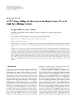
and Baboon. Figure 14 shows the performance comparison
plot for SPIHT-AC, SPIHT-BU, and SPIHT-ZTR in terms
of average PSNR versus the average number of bits sent.
From the simulation results shown in Ta ble 6,itcanbeseen
EURASIP Journal on Embedded Systems 15
Table 6: Performance of the proposed strip-based image coder using SPIHT-ZTR coding and SOT-C structure compared to the traditional
binary uncoded (SPIHT-BU) and arithmetic encoded (SPIHT-AC) SPIHT coding in terms of peak signal-to-noise ratio (dB) versus bit-rate
(bpp) for various grey-scale test images of size 512
× 512 pixels.
Peak Signal-to-Noise Ratio, PSNR (dB)
Bit-rates (Bpp) SPIHT-AC SPIHT-ZTR SPIHT-BU Bit-rates (Bpp) SPIHT-AC SPIHT-ZTR SPIHT-BU
Lenna Barbara
0.25 33.35 32.98 32.91 0.25 26.50 26.16 26.14
0.50 36.56 36.17 36.07 0.50 30.01 29.65 29.60
0.80 38.74 38.46 38.34 0.80 33.35 32.95 32.86
1.00 39.75 39.49 39.31 1.00 34.99 34.46 34.29
Goldhill Peppers
0.25 30.30 29.84 29.91 0.25 34.42 34.04 33.99
0.50 32.82 32.33 32.33 0.50 36.87 36.50 36.48
0.80 34.90 34.62 34.41 0.80 38.35 38.12 37.95
1.00 36.29 35.77 35.66 1.00 39.12 38.85 38.71
Airplane Baboon
0.25 33.35 32.93 32.78 0.25 24.20 24.03 23.88
0.50 37.31 36.81 36.68 0.50 26.49 25.89 25.95
0.80 40.45 40.01 39.83 0.80 28.56 28.25 28.07
1.00 42.01 41.40 41.26 1.00 30.02 29.48 29.38
Table 7: Memory requirements for the strip-based implementation of the traditional SPIHT coding using the original 2 × 2 SOT structure
and our proposed SPIHT-ZTR using SOT-C.
Coding Scheme
DWT SOT Minimum Memory Lines Needed at Type of Spatial Orientation Tree
Scale Scale each subband (DWT / SOT) (SOT) Structure
SPIHT-BU /
4 5 8/32
Original 2 × 2structurewith
SPIHT- AC [5] roots at LL subbands
Strip-based
45 8/8
Roots start from highest
SPIHT [10] LH, HL and HH subbands.
Our proposed Strip-
4 4 8/8 SOT-C with roots at LL subbands
based SPIHT-ZTR
SPIHT-AC
SPIHT-ZTR
SPIHT-BU
0 100 200 300 400 500 600 700
Number of bits sent (Kbits)
14
18
22
26
30
34
38
42
46
PSNR (dB)
Figure 14: Performance comparison of SPIHT-AC, SPIHT-BU and
SPIHT-ZTR in terms of peak signal-to-noise ratio (PSNR) versus
the number of bits sent (Kbits). (The comparison plots are in terms
of average PSNR values and average number of bits sent for all six
test images.)
that our proposed SPIHT-ZTR performs better than the
SPIHT-BU. An average PSNR improvement of 0.14 dB is
obtained at 1.00 bpp using the proposed coding scheme. This
is because the number of bits required to encode the image
at each bit-plane is fewer in SPIHT-ZTR when compared
to SPIHT-BU. In comparison with SPIHT-AC, although
SPIHT-ZTR gives a slightly lower PSNR performance, its
implementation is much less complex since there is no
arithmetic coding in SPIHT-ZTR.
Ta bl e 7 shows the comparison in memory requirements
needed for the strip-based implementation of our proposed
SPIHT-ZTR and that of those needed in [5]and[10]. It
should be noted that in the traditional SPIHT [5] coding,
a six-scale DWT decomposition and a seven-scale SOT
decomposition were originally applied on an image of size
512
× 512 pixels. However, for our comparison to be mean-
ingful, the memory requirements recorded here all involve
a four-scale DWT and a five-scale SOT-decomposition.
From Table 7, it can be seen that our proposed strip-based
16 EURASIP Journal on Embedded Systems
SPIHT-ZTR using SOT-C reduces the memory requirement
by 75% as compared to the traditional SPIHT using the orig-
inal 2
× 2 SOT structure. Even though the strip-based SPIHT
coder proposed in [10] requires the same number of memory
lines as our proposed work, there is a significant degradation
in its performance since the number of zerotrees to be coded
is increased. This hypothesis has been shown in [10, 21].
Lastly, we have also verified that the result output from
our proposed hardware strip-based coder is similar to the
software simulation results.
7. Conclusion
The proposed architecture for strip-based image coding
using SPIHT-ZTR algorithm is able to reduce the complexity
of its hardware implementation considerably and it requires
a very much lower amount of memory for processing
and buffering compared to the traditional SPIHT coding
making it suitable for implementation in severely con-
strained hardware environments such as WSNs. Using the
proposed new 1D addressing method, wavelet coefficients
generated from the DWT module are organized into the
strip-buffer in a predetermined location. This simplifies the
implementation of SPIHT-ZTR coding since the coding can
now be performed in two passes. Besides this, the proposed
modification on the SPIHT algorithm by reintroducing the
degree-0 zerotree coding results in a significant improvement
in compression efficiency. The proposed architecture is suc-
cessfully implemented using our designed MIPS processor
and the results have been verified through simulations using
MATLAB.
References
[1] I. F. Akyildiz, T. Melodia, and K. R. Chowdhury, “Wireless
multimedia sensor networks: a survey,” IEEE Wireless Commu-
nications, vol. 14, no. 6, pp. 32–39, 2007.
[2]A.Mainwaring,J.Polastre,R.Szewczyk,D.Culler,andJ.
Anderson, “Wireless sensor networks for habitat monitoring,”
in Proceedings of the ACM International Workshop on Wireless
Sensor Networks and Applications (WSNA ’02), pp. 88–97,
Atlanta, Ga, USA, September 2002.
[3] I. F. Akyildiz, W. Su, Y. Sankarasubramaniam, and E. Cayirci,
“A survey on sensor networks,” IEEE Communications Maga-
zine, vol. 40, no. 8, pp. 102–105, 2002.
[4] E. Magli, M. Mancin, and L. Merello, “Low-complexity video
compression for wireless sensor networks,” in Proceedings of
the IEEE Internat ional Conference on Multimedia and Expo
(ICME ’03), vol. 3, pp. 585–588, Baltimore, Md, USA, July
2003.
[5] A. Said and W. A. Pearlman, “A new, fast, and efficient image
codec based on set partitioning in hierarchical trees,” IEEE
Transactions on Circuits and Systems for Video Technology, vol.
6, no. 3, pp. 243–250, 1996.
[6] J. M. Shapiro, “Embedded image coding using zerotrees of
wavelet coefficients,” IEEE Transactions on Signal Processing,
vol. 41, no. 12, pp. 3445–3462, 1993.
[7] D. Taubman, “High performance scalable image compression
with EBCOT,” IEEE Transactions on Image Processing, vol. 9,
no. 7, pp. 1158–1170, 2000.
[8] W B. Huang, W. Y. Su, and Y H. Kuo, “VLSI implementation
of a modified efficient SPIHT encoder,” IEICE Transactions on
Fundamentals of Electronics, Communications and Computer
Sciences, vol. 89, no. 12, pp. 3613–3622, 2006.
[9] J. Jyotheswar and S. Mahapatra, “Efficient FPGA imple-
mentation of DWT and modified SPIHT for lossless image
compression,” Journal of Systems Architecture, vol. 53, no. 7,
pp. 369–378, 2007.
[10] R. K. Bhattar, K. R. Ramakrishnan, and K. S. Dasgupta,
“Strip based coding for large images using wavelets,” Signal
Processing, vol. 17, no. 6, pp. 441–456, 2002.
[11] C. Parisot, M. Antonini, M. Barlaud, C. Lambert-Nebout,
C. Latry, and G. Moury, “On board strip-based wavelet
image coding for future space remote sensing missions,” in
Proceedings of the International Geoscience and Remote Sensing
Symposium (IGARSS ’00), vol. 6, pp. 2651–2653, Honolulu,
HI, USA, July 2000.
[12] C. Chrysafis and A. Ortega, “Line-based, reduced memory,
wavelet image compression,” IEEE Transactions on Image
Processing, vol. 9, no. 3, pp. 378–389, 2000.
[13] J. M. Shapiro, “A fast technique for identifying zerotrees in
the EZW algorithm,” in Proceedings of the IEEE International
Conference on Acoustics, Speech and Signal Processing (ICASSP
’96), vol. 3, pp. 1455–1458, 1996.
[14] A. Jensen and l. Cour-Harbo, Ripples in Mathematics: The
Discrete Wavelet Transform, Springer, Berlin, Germany, 2000.
[15] G. Strang and T. Nguyen, Wavelets and Filter Banks,Wellesley-
Cambridge, Wellesley, Mass, USA, 2nd edition, 1996.
[16] M. Weeks, Digital Signal Processing Using Matlab and Wavelets,
Infinity Science Press LLC, Sudbury, Mass, USA, 2007.
[17] W. Sweldens, “The lifting scheme: a custom-design construc-
tion of biorthogonal wavelets,” Applied and Computational
Harmonic Analysis, vol. 3, no. 2, pp. 186–200, 1996.
[18] K C. B. Tan and T. Arslan, “Shift-accumulator ALU centric
JPEG2000 5/3 lifting based discrete wavelet transform archi-
tecture,” in Proceedings of the IEEE International Symposium on
Circuits and Systems (ISCAS ’03), vol. 5, pp. V161–V164, 2003.
[19] T. Archarya and P S. Tsai, JPEG2000 Standard for Image
Compression: Concepts, Algorithms and VLSI Architectures,
Wiley-Interscience, New York, NY, USA, 2004.
[20] M. E. Angelopoulou, K. Masselos, P. Y. K. Cheung, and Y.
Andreopoulos, “Implementation and comparison of the 5/3
lifting 2D discrete wavelet transform computation schedules
on FPGAs,” Journal of Signal Processing Systems, vol. 51, no. 1,
pp. 3–21, 2008.
[21] L.W.Chew,L M.Ang,andK.P.Seng,“NewvirtualSPIHT
tree structures for very low memory strip-based image
compression,” IEEE Signal Processing Letters, vol. 15, pp.
389–392, 2008.
[22] E. Khan and M. Ghanbari, “Very low bit rate video coding
using virtual SPIHT,” Electronics Letters, vol. 37, no. 1, pp.
40–42, 2001.
[23] F. W. Wheeler and W. A. Pearlman, “SPIHT image
compression without lists,” in Proceedings of the IEEE
InternationalConferenceonAcoustics,SpeechandSignal
Processing (ICASSP ’00), vol. 4, pp. 2047–2050, Istanbul,
Turkey, June 2000.
[24] W K. Lin and N. Burgess, “Listless zerotree coding for color
images,” in Proceedings of the 32nd Asilomar Conference on
Signals, Systems and Computers, vol. 1, pp. 231–235, Monterey,
Calif, USA, November 1998.
[25] D. A. Patterson and J. L. Hennessy, Computer Organization and
Design: The Hardware/Software Interface, Morgan Kaufmann,
San Francisco, Calif, USA, 2nd edition, 1998.