Drilling and Associated Cutting Tool Technology Industrial Handbook_1 pdf
Bạn đang xem bản rút gọn của tài liệu. Xem và tải ngay bản đầy đủ của tài liệu tại đây (615.67 KB, 9 trang )
3
Drilling and Associated
Technologies
‘In all things, success depends upon previous preparation
and without such preparation……there is sure to be failure.’
(c550–c487BC)
[Analects]
3.1 Drilling Technology
.. Introduction to the Twist
Drill’s Development
Drilling operations are perhaps the most popular ma-
chining process being undertaken today, with their
origins being traced back to cutting tool develop-
ments in North America in the 19
th
century. In 1864
toward the latter part of the American Civil War, Ste-
ven Morse (i.e. later to design the signicant ‘Morse
taper’ – for accurate location of the ‘sleeved drills’
into their mating machine tool spindles) founded
the Morse Twist Drill and Machine Company in the
‘North’. Morse then proceeded to develop probably the
most important cutting tool advance to date, namely,
the ubiquitous twist drill. In Fig. 42, several of today’s
twist drills are illustrated along with just a small range
of ‘solid’ contemporary designs. Morse’s originally-de-
signed twist drill has changed very little over the last
150 years – since its conception. In comparison to the
somewhat cruder-designed contemporary drills of that
time, Morse stated: ‘e common drill scrapes metal to
be drilled, while mine cuts the metal and discharges the
chips and borings without clogging’. Morse’s statement
was at best, to some extent optimistic, whereas the
‘cold reality’ tells a dierent story, as a drill’s perfor-
mance is inuenced by a considerable number of fac-
tors, most of which are listed in Fig. 43.
.. Twist Drill Fundamentals
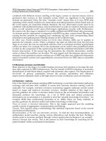
e basic construction of a conventional twist drill is
depicted in Fig. 44a. From this illustration two dis-
tinct cutting regions can be established: rstly, the
main cutting edge, or lips; secondly at the intersection
of the clearance and main cutting edge – termed the
chisel edge. In fact for a twist drill, the cutting process
can be equated to that of a le-hand oblique turning
tool, where the rake and clearance face geometries are
identical and the correlation between these two ma-
chining processes have been validated in the experi-
mental work by Witte in 1982. Both of these regions
remove material, with the cutting lips producing ef-
cient material removal, while the chisel edge’s con-
tribution is both inecient and is mainly responsible
for geometric errors in drilling, coupled to high thrust
loads.
e main cutting edges are accountable for a rela-
tively conventional chip formation, as shown in the
‘quick-stop’ photomicrograph in Fig. 44b. An oblique
cutting action occurs to the direction of motion, being
the result of an oset of the lips that are parallel to a
radial line – ahead of centre – which is approximately
equal to half the drill point’s web thickness and in-
creases toward the centre of the drill. is obliquity is
responsible for inducing chip ow in a direction nor-
mal to the lips in accordance with Stabler’s Law
1
. e
increasing chip ow obliquity can be seen in Fig. 45a,
by observing the ow lines emanating from the chip’s
interface along the lips and up the ute face. Such
an oblique cutting action serves to increase the twist
drill’s eective rake angle geometry. With the advent
of ‘Spherical trigonometric computer soware’ for ob-
taining direct three-dimensional calculations – previ-
ously described by Witte (1982) in two-dimensional
formulae for cutting edge performance – these calcu-
lations have been enhanced.
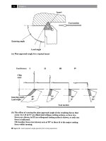
Under the chisel point, or web, the material re-
moval mechanism is quite complex. Near the bottom
of the utes where the radii intersect with the chisel
edge, the drill’s clearance surfaces form a cutting rake
surface that is highly negative in nature. As the centre
of the drill is approached, the drill’s action resembles
that of a ‘blunt wedge-shaped indentor’ , as illustrated
in Fig. 45b. An indication of the inecient material
removal process is evident by the severe workpiece
deformation occurring under the chisel point, where
such deformed products must be ejected by the drill to
produce the hole. ese ‘products’ are extruded, then
wiped into the drill ute whereupon they intermingle
with the main cutting edge chips. is fact has been
substantiated by force and energy analysis, based on a
combination of cutting and extruding behaviour under
the chisel point, where agreement has been conrmed
with experimental torque and thrust measurements.
e chisel edge in a conventionally ground twist drill
has no ‘true’ point, which is one of the major sources
for a drilled hole’s dimensional inaccuracy.
1 Stabler’s Law – for oblique cutting, can be formulated, as be-
low:
Chip ow (cos η) = cos I (b
c
/b)
Where: I = inclination of cutting edge, b
c
= chip ow vector,
b = direction of cutting vector.
Chapter
e conventional twist drill chisel point geometry
can be seen in Fig. 46, together with associated no-
menclature for critical features and tolerance bound-
aries. From the relatively complex geometry and
dimensional characteristics shown in Fig. 46, the ob-
tainable accuracy of holes generated whilst drilling is
dependent upon grinding the drill to certain limits.
Any variations in geometry and dimensions, such as:
dissimilar lips and angles, chisel point not centralised,
and so on, have a profound eect on both the hole di-
Figure 42. A selection of just some of the many ‘solid’ and ‘through-spindle’ drilling varieties and ‘inserted-edge’
insert geometries currently available. [Courtesy of Seco Tools]
.
Drilling and Associated Technologies
Figure 43. The principal technical drill performance criteria and factors associated with drilling operations in this case for ex-
ample, on castings
.
Chapter
Figure 44. The twist drill geometry and associated chip shearing mechanism. [Source: C.J. Oxford Jr., 1955].
Drilling and Associated Technologies
Figure 45. The twist drill shearing and extrusion mechanism at the bottom of a hole. [Source:
C.J. Oxford Jr., 1955]
.
Chapter
Figure 46. Twist drill geometry.
Drilling and Associated Technologies
mensional accuracy and roundness, with some ‘helical
wandering’
2
as the drill passes through the workpiece.
Hole accuracy and in particular the ‘bell-mouthing ef-
fect’
3
, is minimised by previously centre-drilling prior
to drilling to ‘size’. e main cause of such this ‘bell-
mouthing’ is probably the inconsistency in the drill
geometry. Such eects are exacerbated using Jobber
drills
4
, or even worse, by utilising longer-series drills,
which tend to either slightly ‘unwind’ , or bend as a re-
sult of lessening rigidity promoting some drill bend-
ing/deection.
It is worth noting that the rigidity of a tool such
as a drill will decrease by the ‘square of the distance’
5
.
erefore it follows that the greater the drill penetra-
tion into the workpiece, the progressively larger the
deection and, the further from the ‘true axis of rota-
tion’ will be the subsequent drill’s path. is deected
drilled hole slope angle ‘ϕ’ , can be dened in the fol-
lowing manner:
Drilled hole slope angle
‘φ’ = 3/2 l × R/T (1 – I/k × tan k l)
Where:
l = length of deected tool,
2 ‘Helical wandering’ is the result of the drill’s geometry be-
ing ‘unbalanced’ , resulting from of diering lip lengths, or an
oset chisel point, causing the drill to ‘spiral-down’ through
the workpiece, as it progresses through the part (see Fig. 70).
‘Bell-mouthing’ of the drilled hole is attributable to the chisel
point and is produced by the line-of-contact, as the drill point
initially touches the component’s surface, causing it to ‘walk’
until the feed/penetration stabilises itself at the outer corners
(i.e. margins) entering the workpiece, whereupon, these mar-
gins guide the drill into the part.
3 ‘Bell-mouthing eect’ is produced by the drill chisel point’s
eccentric behaviour as it attempts to centralise its rotational
motion as it enters, or exit’s the workpiece.
4 ‘Jobber drills’ are considered to be ‘standardised drills’ that
are normally utilised for most drilling general operations, un-
less otherwise specied.
5 ‘Rigidity rule’: a drill, reamer, tap, or a milling cutter held in
a spindle will have its rigidity decreased by the ‘square of the
distance’ , namely, if a drill is twice as long it is four times less
rigid.
NB A cantilevered tool such as a boring bar has its rigidity de-
creased by the ‘cube’ or the distance – meaning that too much
tool overhang, will seriously reduce tooling rigidity.
R = ratio of the transverse reaction at the drill point,
T = thrust force,
I = system’s ‘moment of inertia’ ,
k = √T/E I.
As suggested above, this ‘axis slope error’ is initiated
when the chisel edge begins to penetrate the workpiece
and unless the feed is discontinued, or in some man-
ner the error is corrected, the magnitude of deection
will increase as drill penetration continues. e drill’s
magnitude of deection can reach up to 60 µm, under
exaggerated drilling conditions.
e geometry of the point has been the subject
of considerable research and development for many
years, with some unusual departures from the ‘stan-
dard’ 118° drill point included angle. Typical of these
extreme approaches were the so-called ‘Volvo point’ ,
having a negative 185° included angle – primarily
utilised to avoid ‘frittering’
6
of drilled holes, or the
highly positive geometries such as 80° included an-
gle used for drilling some plastics. Not only can the
point angle be modied, but the shape and prole of
the chisel point, or web
7
oers numerously-ground
opportunities for detailed geometric modications,
with only some of which being shown in Fig. 47. Four
of the most commonly-ground drill point geometries
being:
•
Conventional – the ‘original’ Morse geometry, hav-
ing a straight chisel edge, with poor self-centring
drilling action (Fig. 46a),
•
Split-point
8
– there are a range of point-splitting
techniques available to alter the point prole, which
has the eect of modifying the chisel point to allow
a reasonable self-centring action (Fig. 47b),
6 ‘Frittering’ refers to the break-out at the hole’s edge as the drill
exit’s the part, on some brittle materials, such as on several
Powder Metallurgy compacts.
7 ‘Web’ refers to the internal core of the drill – which imparts
mechanical strength to the drill. e web increases in thick-
ness the further one gets from the chisel edge (i.e. shown in
Fig. 47 – in lower diagrams and with cross-sections). Hence,
if the drill is reground many times, the chisel point width will
obviously increase, this necessitates that the chisel point must
be ‘thinned’ , otherwise too high a thrust force occurs and an
inecient drilling action will result.
8 ‘Split-point’ ground drills are sometimes referred to as ‘Multi-
facet drills’.
Chapter
Figure 47. A range of typically ground twist drill points.
Drilling and Associated Technologies