Three Dimensional Integration and Modeling A Revolution in RF and Wireless Packaging by Jong Hoon Lee Emmanuil Manos M Tentzeris and Constantine A Balanis_3 ppt
Bạn đang xem bản rút gọn của tài liệu. Xem và tải ngay bản đầy đủ của tài liệu tại đây (11.71 MB, 12 trang )
THREE-DIMENSIONAL PACKAGING IN MULTILAYER ORGANIC SUBSTRATES 15
FIGURE 3.2: Fabric ated RF MEMS switch.
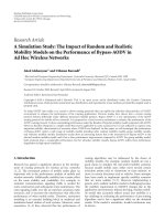
FIGURE3.3: Comparison of S-parameter measurements of an air-bridge type CB-FGC MEMS switch
in the “UP” state. (Case 1) The switch is measured in open air. (Case 2) The packaging layer is brought
down and taped into hard contact and measured. (Case 3) A top metal press plate and a 15 lbwt are put
on top of the packaging layer (15 psi) to simulate bonding pressure. The weight and press plate are then
removed and the switch is remeasured.
16 THREE-DIMENSIONAL INTEGRATION
FIGURE3.4: Comparison of S-parameter measurements of an air-bridge type CB-FGC MEMS switch
in the “DOWN” stage. The three measurement cases shown are identical to those shown in Fig. 3.3.
ensured that the alignment of the package cavities was successful. Finally, the top metal plate was
placed over the alignment pins and a 15 lbwt was balanced on top of the samples to simulate the
pressure from a bonding process. The plate was removed and the samples were remeasured. Results
for these measurements are shown in Figs. 3.3 and 3.4.
The S-parameters of the packaged switch and the nonpackaged switch are nearly identical in
both the up and down states. For example, the variation between the three measurement cases for
S21 in the “UP” state only varies by an average of 0.032 dB across the entire measurement band.
The other S-parameter comparisons with and without the package layer are very similar.
3.2.3 Transmission Lines with Package Cavities
To show the effects of the packaging layer and cavity on a simple transmission line, the switch
membrane was physically removed and the circuit remeasured. The results of the bare transmission
line with and without the packaging layer are shown in Fig. 3.5. As expected from these simulations,
the cases with and without the packaging layer are very similar.
3.3 ACTIVE DEVICE PACKAGING USING
MULTILAYER LCP SUBSTRATES
Active devices, specifically GaAs MMICs, are robust to humidity and temperature testing. The gold
metallization on GaAs chips relieves several of the problems that plague Si MMICs, which have
THREE-DIMENSIONAL PACKAGING IN MULTILAYER ORGANIC SUBSTRATES 17
FIGURE 3.5: Comparison of S-parameter measurements of the MEMS switch transmission line after
the switch was physically removed. The cases with the package and without the package layer are nearly
the same.
FIGURE 3.6: Pictorial side view of the package stackup.
aluminum contacts. However, for a reliable and long-term operation, a substantial sealed package
is still desired to protect GaAs MMICs from the environment. In addition, to create compact,
inexpensive RF modules, new packaging concepts and convenient integration techniques of com-
bining passive and active devices are required. One such technique, which operates similar to the
18 THREE-DIMENSIONAL INTEGRATION
low-temperature co-fired ceramic (LTCC) fabrication flow, but whose laminated temperature is low
enough for embedding chips, is bonding multiple thin-film LCP substrates into a package with
embedded cavities for MEMS or monolithic microwave integrated circuits (MMICs) [59].
3.3.1 Embedded MMIC Concept
The idea for embedding a MMIC in a multilayer dielectric substrate/package for creating compact
RF modules is not new. LTCC is a material technology that allows the space savings of embedding
passive elements on many vertically connected layers. Unfortunately, LTCC has a firing temperature
of 850
◦
C, which means that the inclusion of MMICs must be done with some external assembly
process after fir ing. This c an involve soldering plastic leaded chips onto the top layer or using
other methods to embed chips in cavities between already fired LTCC boards. Since LCP has a
lamination temperature of 285
◦
C, chips can be included directly inside the LCP layer stackup and
laminated/packaged during the same thermocompression bonding process that seals the rest of the
passive element layers together. Two issues that are important for the reliability of active devices
are coefficient of thermal expansion (CTE) matching at the semiconductor connection points, and
thermal heat dissipation. To prove the concept of a robust multilayer LCP packaged MMIC and to
address these issues, the package design shown in Fig. 3.6 was devised.
The coefficient of thermal expansion (CTE) of the chip’sgoldground plane [14.4 (ppm/
◦
C)] is
well matched tothespecialinorganicsilverepoxy adhesiveandcopperlayers[bothwith17(ppm/
◦
C)]
to which its base is attached. In addition, this contact location is excellent for heat dissipation as the
chip is directly connected to the large copper RF ground plane. However, to be realistic about the
CTE match, the base of the chip may not be the most sensitive area of concern. It is more likely to
be of importance in locations where the chip contacts connect to feed lines. Fortunately, LCP’s CTE
in the x–y plane can be engineered to match both metals and semiconductors at the expense of slight
changes to the z-CTE. LCP with the CTE of 5 ppm/
◦
C are used for semiconductor attachment
and layers with the CTE of 17 ppm/
◦
C are used in layers where matching the copper metallization.
For reference, copper has a CTE of 17 ppm/
◦
C and GaAs has a CTE of 5.8 ppm/
◦
C.
3.3.2 MMIC Package Fabr ication
Se veral laser micromachining process steps were used to create the multilayer LCP package. First,
an excimer laser was used to form the chip cavit y in the base substrate layer by ablating LCP down
to the 18m copper ground plane. The standard 4 mil GaAs MMIC thickness is the same as an
off-the-shelf LCP thickness so that the top of the chip is coplanar with feeding transmission lines
on the LCP substrate. A Hittite HMC342 13–25 GHz low noise amplifier and an off-chip parallel
plate bypass capacitor from Presidio Components Inc. were then affixed to the ground plane with
an inorganic high temperature silver paste. These assembly steps are shown graphically in Fig. 3.7.
THREE-DIMENSIONAL PACKAGING IN MULTILAYER ORGANIC SUBSTRATES 19
FIGURE3.7: Comparison of the LCP laser machined base layer before and after the MMIC and parallel
plate capacitor were mounted with an inorganic silver paste and wire bonded to the feed lines.
The superstrate packaging layers were machined with a CO
2
laser to form square holes in some
layers for the chip c avity while leaving other layers solid to create a sealed cavity after lamination. All
the layers including the base substrate had laser cut alignment holes in the same relative locations to
enable precise stac king on an aluminum bonding fixture. The final laminated package on the fixture
with the top press plate removed is shown Fig. 3.8.
3.3.3 MMIC Package Testing
The important proof-of-concept for the packaging of the MMIC is that a seal can be created around
the 18-m thick feeding transmission lines. These transmission lines pass directly through the
side of the package stackup and require a 2 mil (50 m) low melting temperature LCP bond layer
to melt and conform around them to create a seal. Figure 3.9 shows a scale representation of the
height of LCP’s default metallization to the height of the bond ply. A closeup picture of the actual
transmission line feedthrough, which demonstrates the ability of the LCP material to conform
around the transmission line, is shown in Fig. 3.9.
To test the package seal, the packaged MMIC was submersed in water for 48h. The sam-
ple was held on edge while underwater to encourage any potential cavity leaks to be breached. A
through-reflect-line (TRL) calibration was performed with an identical alternate sample so that the
measurement of the packaged chip could be made immediately upon removal from the water. The
gain of the packaged MMIC was then measured and compared with the gain before the submersion
test. The results of this test are shown in Fig. 3.10.
20 THREE-DIMENSIONAL INTEGRATION
FIGURE 3.8: Top view of the 13–25 GHz GaAs MMIC packaged in multiple thin layers of LCP.
FIGURE 3.9: LCP transmission line (18 m thick) passing directly through the side of a bonded
superstrate package stackup.
THREE-DIMENSIONAL PACKAGING IN MULTILAYER ORGANIC SUBSTRATES 21
FIGURE 3.10: Gain measurement of the Hittite HMC342 13–25GHz LNA. The first measurement
was of the packaged/bonded MMIC. The second measurement was done immediately after the packaged
MMIC was submerged in water on edge for 48 h. The match of the measurements demonstrates as
successful seal by the LCP package. The minimal water absorption into the package shows no significant
effect on the MMIC performance.
The gain measurement in the before/after states is identical, indicating that the multilayer
LCP MMIC package method can be used successfully for packaging active devices.
3.4 THREE-DIMENSIONAL PAPER-BASED MODULES FOR
RFID/SENSING APPLICATIONS
As the demand for low-cost, flexible and efficient electronics increases, the materials and integra-
tion technologies become more critical and face many challenges, especially with the ever growing
interest for “cognitive intelligence” and wireless applications, such as r adio frequency identifica-
tion (RFID) and wireless local area networks (WLAN). Paper has been considered as one of the
best organic-substrate candidates for ultrahigh frequency (UHF) and microwave applications such
as RFID/sensing. It is not only environmentally friendl y, but can also undergo large reel-to-reel
processing. In terms of mass production and increased demand, this makes paper the lowest cost
material made. Paper also has low surface profile with appropriate coating. This is very crucial since
fast printing processes, such as direct wr ite methodologies, can be utilized instead of metal etching
techniques. A fast process, like inkjet printing, can be used efficiently to print electronics on/in paper
substrates.
22 THREE-DIMENSIONAL INTEGRATION
FIGURE 3.11: Inductively coupled feeding RFID tag module configuration.
First of all, the RF characteristics of the paper-based substrate have been recently studied by
using the cavity resonator method and the transmission line method to characterize the dielectric
constant (ε
r
) and loss tangent (tan ı) of the substrate [60]. The results show ε
r
= 1.6 at Ka band and
tan ı<0.082 up to 2.4 GHz. Then, aUHF RFID tag module was developed with the inkjet-printing
technology that could function as a technology for much simpler and faster fabrication on/in paper.
Most available commercial RFID tags are passive, and the antenna translates electromagnetic waves
from the reader into power supplied to the IC. Thus, a conjugate impedance matching between
antenna and the tag IC is highly essential to power up the IC and maximize the effective range, and
so an inductively coupled feeding structure is an effective way for impedance matching.
FIGURE 3.12: Measured and simulated input resistance and reactance of the inkjet-printed RFID tag.
THREE-DIMENSIONAL PACKAGING IN MULTILAYER ORGANIC SUBSTRATES 23
As a benchmark of this approach, an inductively coupled feeding RFID tag module was
inkjet-printed and its configuration is shown in Fig. 3.11. The target RFID IC was EPC Gen2
RFID ASIC IC, which has a stable impedance performance of 16-j350 Ohm over 902–928MHz,
covering the North America UHF RFID Band. The substrate was the previously character ized
paper. To ensure that the ink droplets overlap sufficiently, a 25 m drop spacing was selected. After
inkjet printing, a low-temperature sintering step guaranteed a continuous metal conductor,providing
a good percolation channel for the conduction electrons to flow. The measured and simulated RFID
tag input impedance are shown in Fig. 3.12. Since the conductivity of the conductive ink varies from
0.4–2.5 ×10
7
siemens/m depending on the curing temperature [57], the input resistance was slightl y
higher due to the additional metal loss introduced. Overall, a ver y good agreement was observed over
the frequency band of interest. It is quite clear that paper will become a commonly used material in
3D integration and packaging of the future, due to its ultra-low cost, ease of multilayer lamination in
very low temperatures (∼150
◦
C) and it enevironmentally-friendly (“gree”) characteristics, especially
in the UHF and Wireless frequency bands.
24
25
CHAPTER 4
Microstrip-Type Integrated Filters
4.1 PATCH RESONATOR FILTERS AND DUPLEXERS
4.1.1 Single Patch Resonator
Integrating filter-on-package in low-temperature cofired ceramic (LTCC) multilayer technology is a
very attractive option for radio frequency (RF) front-ends up to the millimeter-wave frequency range
in termsofboth miniaturization byvertical deploymentoffilterelements and reductionof the number
of components and assembly cost by eliminating the demand for discrete filters. In millimeter-
wave frequencies, the bandpass filters are commonly realized using slotted patch resonators because
of their miniaturized size and their excellent compromise among size, power handling, and
easy-to-design layout [17]. In this section, the design of a single-pole slotted patch filter is presented
for two operating frequency bands (38–40 GHz and 58–60 GHz). This design can be easily gener-
alized to multiband applications, especially for portable wireless modules that the size and weight
is of paramount importance. Its major advantages are its capability of high-Q structures in vertic al
stackups and the easy addition of multiple stages for high-selectivity applications.
Figure 4.1(a) and (b) shows a top-view comparison between a basic half-wavelength
(/2) square patch resonator (L ×L =0.996 mm ×0.996 mm) [61] and the new configuration
(L ×L =0.616 mm ×0.616 mm), respectively, that is capable of providing good tradeoffs between
miniaturization and power handling. Side views and the photographs of the 60 GHz resonators are
shown in Figs. 4.2 and 4.3, respectively. In the conventional design of a /2 square patch, the planar
single-mode patch and microstrip feedlines are located on metal 3 (M3 in Fig. 4.2) and they use
the end-gap capacitive coupling between the feedlines and the resonator itself to achieve 3% 3-dB
bandwidth and <3 dB insertion loss around the center frequency of 60 GHz. However, the required
coupling capacitances to obtain design specifications could not be achieved because of the LTCC
design rule limitations.
To maximiz e the coupling strength while minimizing the effects of the fabrication, the pro-
posed novel structure takes advantage of the vertical deployment of filter elements by placing the
feedlines and the resonator into different vertical metal layers, as shown in Fig. 4.2. This transi-
tion also introduces a 7.6% frequency downshift resulting from the additional capacitive coupling
effect compared to the basic /2 square patch resonator [Fig. 4.1(a)] directly attached by feedlines.
Transverse cuts have been added on each side of the patch to achieve significant miniaturization of
the patch by contributing an additional inductance. Figure 4.4 shows the simulated response for the
26 THREE-DIMENSIONAL INTEGRATION
FIGURE 4.1: Top view of (a) conventional /2 square patch (b) Miniaturized patch resonator.
FIGURE 4.2: Side view of 60 GHz slotted 3D patch resonator.