Three Dimensional Integration and Modeling A Revolution in RF and Wireless Packaging by Jong Hoon Lee Emmanuil Manos M Tentzeris and Constantine A Balanis_4 docx
Bạn đang xem bản rút gọn của tài liệu. Xem và tải ngay bản đầy đủ của tài liệu tại đây (1.42 MB, 12 trang )
MICROSTRIP-TYPE INTEGRATED FILTERS 27
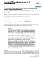
FIGURE 4.3: Photograph of the fabricated filters with coplanar waveguide (CPW) pads at 60GHz.
center frequency and the insertion loss as the length of cuts [L
CL
in Fig. 4.1(b)] increases, while the
fixed width of cuts [L
CW
=L/8 in Fig. 4.1(b)] is determined by the fabrication tolerance. It can
be observed that the operating frequenc y range shifts further downward about 33% as the length
of the cut [L
CL
in Fig. 4.1(b)] increases by approximately 379 m. Additional miniaturization is
limited by the minimum distance [L
S
in Fig. 4.1(b)] between the corners of adjacent orthogonal
cuts. Meanwhile, as the operating frequency decreases, the shunt conductance in the equivalent cir-
cuit of the single patch also decreases because its value is reciprocal to the exponential function of
the operating frequency [62]. This fact additionally causes the reduction of radiation loss since it is
proportionally related to the conductance in the absence of conductor loss [62]. Therefore, insertion
loss at resonance is improved from 2.27 dB to 1.06 dB by an increase of L
CL
in Fig. 4.1(b).
FIGURE 4.4: Simulated responses of center frequency ( f
0
) and insertion loss (|S21|) as a function of
transverse cut (L
CL
).
28 THREE-DIMENSIONAL INTEGRATION
FIGURE 4.5: Simulated 3-dB bandwidth as function of overlap distance of 60 GHz slotted
patch resonator.
The patch size is reduced significantly from 0.996 to 0.616 mm. The modification of band-
width resulting fromthe patch’s miniaturization canbecompensated byadjustingthe overlap distance
(L
over
). Figure 4.5 shows the simulated response for the 3-dB bandwidth as L
over
increases. It is
observed that the 3-dB bandwidth increases almost linearly as L
over
increases because of a stronger
coupling effect; L
over
is determined to be 18 m corresponding to the 1.85GHz 3-dB bandwidth.
The proposed embedded microstrip line filters can be easily excited through vias connecting
the coplanar waveguide (CPW) signal pads on the top metal layer (M1 in Fig. 4.2), reducing the
paraisitc radiation loss compared to conventional microstrip lines on the top (surface) layer. As
shown in Fig. 4.1(b), K lopfenstein impedance tapers are used to connect the 50 feeding line and
the via pad on metal 2 (M2 in Fig. 4.2). The overlap (L
over
≈L/31) and transverse cuts (L
CW
≈L/8,
L
CL
≈L/3.26) have been finally determined to achieve desired filter characteristics. The filters with
CPW pads have been fabricated in LTCC (ε
r
= 5.4, tan ı =0.0015) with a dielectr ic layer thickness
of 100 m and metal thickness of 9 m. The overall size is 4.018 mm ×1.140 mm ×0.3mm,
including the CPW measurement pads. As shown in Fig. 4.6, the experimental and the simulated
results agree very well. It can be easily observed that the insertion loss is <2.3 dB, the return loss
>25.3 dB over the passband and the 3-dB bandwidth is about 1 GHz. The center frequency shift
from 59.85 to 59.3 GHz can be attributed to the fabrication accuracy (vertical coupling over lap
affected by the alignment between layers and layer thickness tolerance).
MICROSTRIP-TYPE INTEGRATED FILTERS 29
FIGURE 4.6: Measured and simulated S-parameters of 60 GHz slotted patch resonator.
4.1.2 Three and Five-Pole Resonator Filters
The next step for the easy and miniaturized realization of better rejection and selectivity would be
the design of multistage filters. The presented example in this section deals with the design and
fabrication of symmetrical three-pole and five-pole filters for intersatellite wideband applications
that consist of, respectively, three and five capacitively gap-coupled single-mode resonators, as shown
Fig. 4.7(a) and (b).
FIGURE 4.7: Top view of (a) three-pole slotted patch bandpass filter (b) five-pole slotted patch
bandpass filter.
30 THREE-DIMENSIONAL INTEGRATION
FIGURE 4.8: Side view of (a) three-pole slotted patch bandpass filter (b) five-pole slotted patch
bandpass filter.
The first three-pole bandpass filter was developed for a center frequency of 59.6 GHz,
1dB insertion loss, 0.1 dB in band ripple, and 6.4% fractional bandwidth based on Chebyshev
low-pass prototype filter. The design parameters, such as the external quality factors and the coupling
coefficients, were
Q
ext
= 15.4725
k
12
= k
23
= 0.06128.
To determine the physical dimensions, full-wave electromagnetic (EM) simulations (IE3D)
were used to extract the coupling coefficients (k
ii+1,
i =1 or 2) and external quality factors (Q
ext
)
based on a simple graphical approach as described in [63]. Feeding lines and slotted patch resonators
were alternately positioned on different metal layers (feeding lines, 2nd resonator: M2; 1st resonator,
3rd resonator: M3) as shown in Fig. 4.8(a),(b) to achieve strong k
ii+1
between resonators as well as
desired Q
ext
between resonator and feeding line with a moderate sensitivity to the LTCC fabrication
tolerances. The benefits of the multilayer filter topologies in terms of miniaturization can be easily
observed in F ig. 4.8.
MICROSTRIP-TYPE INTEGRATED FILTERS 31
FIGURE 4.9: (a) External quality factor (Q
ext
) evaluated as a function of overlap distance (L
over
) (b)
Coupling coefficient, k
12
, as a function of coupling spacing (d
12
) between 1st resonator and 2nd resonator.
Figure 4.9(a) shows the Q
ext
evaluated as a function of overlap distance (L
over
). A larger
L
over
results in a stronger input/output coupling and smaller Q
ext
. Then, the required k
ij
is obtained
against the variation of distance [d
ij
in Fig. 4.7(a)] for a fixed Q
ext
at the input/output ports. Full-
wave simulation was also employed to find two characteristic frequencies (f
p1
, f
p2
) that represent
32 THREE-DIMENSIONAL INTEGRATION
FIGURE 4.10: Measured and simulated S-parameters of three-pole slotted patch bandpass filter.
resonant frequencies of the coupled structure when an electrical wall or a magnetic wall, respectively,
was inserted in the symmetrical plane of the coupled structure [63]. Character istic frequencies
were associated with the coupling between resonators as follows: k = ( f
2
p2
− f
2
p1
)/( f
2
p2
+ f
2
p1
) [4]. The
coupling spacing [d
12
in Fig. 4.7(a)] between the first and second resonators for the required k
12
was
determined from Fig. 4.9(b). k
23
and d
23
are determined in the same way as k
12
and d
12
since the
investigated filter is symmetrical around its center.
Figure 4.10 shows the comparison of the simulated and the measured S-parameters of the
three-pole slotted patch filter. Good correlation is observed, and the filter exhibits an insertion loss
<1.23 dB, the return loss >14.31 dB over passband, and the 3-dB bandwidth about 6.6% at center
frequency 59.1 GHz.The selectivity onthe highside ofthepassband isbetter thantheEMsimulation
because an inherent attenuation pole occurs at the upper side. The latter is due to the fact that the
space between fabricated nonadjacent resonators might be smaller than that in simulation so that
strongercross couplingmight occur. Inaddition, themeasured insertionlossis slightlyhigher thanthe
theoretical result because of additional conductor loss and radiation loss from the feeding microstrip
lines that cannot be de-embedded bec ause of the nature of short, open, load, and thru (SOLT )
calibration method. The dimensions of the fabricated filter are 5.855 mm ×1.140 mm ×0.3mm
with measurement pads.
MICROSTRIP-TYPE INTEGRATED FILTERS 33
A high-order filter design using five-slotted patches [Fig. 4.7(b)] and having very similar
coupling scheme as the three-pole filter is also presented as an example for large (>3) number of filter
stages. TheChebyshev prototype filterwas designedfor a centerfrequency of61.5GHz, 1.3 dBinser-
tion loss, 0.1 dB band ripple, and 8.13% 3-dB bandwidth. The circuit parameters for this filter are:
Q
ext
= 14.106
k
12
= k
45
= 0.0648
k
23
= k
34
= 0.0494
Figure 4.8(b) shows the side view of a five-pole slotted patch bandpass filter. The feeding lines
and the open-circuit resonators have been inserted into the different metallization layers (feeding
lines: 2nd and, 4th resonators M2; 1st, 3rd, and 5th resonator: M3) so that the spacing between
adjacent resonators and the overlap between the feeding lines and the resonators work as the main
parameters of the filter design to achieve the desired coupling coefficients and the external quality
factor in a very miniaturized configuration. The filter layout parameters are d
12
=d
45
≈
go
/16,
d
23
=d
34
≈
go
/11, L
over
≈
go
/26 [Fig. 4.7(b)], where
go
is the guided wavelength and the filter
size is 7.925 ×1.140 ×0.3 mm
3
.
The measured insertion and reflection loss of the fabricated filter are compared with the
simulated results in Fig. 4.11. The fabricated filter exhibits a center frequency of 59.15 GHz, an
FIGURE 4.11: Measured and simulated S-parameters of five-pole slotted patch bandpass filter.
34 THREE-DIMENSIONAL INTEGRATION
insertion loss of about 1.39 dB, and a 3-dB bandwidth of approximately 7.98%. These multipole
filters can be used in the development of compact multi-pole duplexers. The difference between the
measurement and simulation is attributed to the fabrication tolerances, as mentioned in the c ase of
the three-pole bandpass filter.
4.2 QUASIELLIPTIC FILTER
Numerous researchers [63,64] have demonstrated narrow bandpass filters employing open-loop res-
onators for current mobile communication services at L- and S-bands. In this section, the design
of a four-pole quasielliptic filter is presented as a filter solution for LTCC 60 GHz front-end mod-
ule because it exhibits a superior skirt selectivity by providing one pair of transmission zeros at
finite frequencies, enabling a performance between that of the Chebyshev and elliptical-function
filters [63]. The very mature multilayer fabrication capabilities of LTCC (ε
r
=7.1, tan ı =0.0019,
metal layer thickness, 9 m; number of layers, six; dielectric layer thickness, 53m; minimum metal
line width and spacing, up to 75 m) make it one of the leading competitive solutions to meet
millimeter-wave design requirements in terms of physical dimensions [63] of the open-loop res-
onators (≈0.2
g
×0.2
g
), achieving a significant miniaturization because of relatively high ε
r
, and
spacing (≥80 m) between adjacent resonators that determine the coupling coefficient of the filter
function.
Figure 4.12(a) and (b) shows the top and cross-sectional views of a benchmarking microstrip
quasielliptic bandpass filter, respectively. The filter was designed according to the filter synthesis
proposed by Hong and Lancaster [63] to meet the following specifications:
1. Center frequency: 62 GHz;
2. Fractional bandwidth: 5.61% (∼3.5 GHz);
3. Insertion loss: <3 dB (4) 35 dB rejection bandwidth: 7.4 GHz;
4. Its effective length [R
L
in Fig. 4.12(a)] and width [R
W
in Fig. 4.12(a)] has been optimized to
be approximately 0.2
g
using a full-wave simulator (IE3D) [63]. The designparameters,such
as the coupling coefficients (C
12
, C
23
, C
34
, C
14
) and the Q
ext
can be theoretically determined
by the formulas [63].
Q
ext
=
g
1
FBW
C
i,i+1
= C
n−i,n−i+1
=
FBW
√
g
i
g
i+1
for i = 1tom −1
C
m,m+1
=
FBW J
m
g
m
C
m−1,m+2
=
FBW J
m−1
g
m−1
(4.1)
MICROSTRIP-TYPE INTEGRATED FILTERS 35
FIGURE 4.12: (a) Top view and (b) cross-sectional view of four-pole quasielliptic bandpass filter con-
sisting of open-loop resonators fabricated on LTCC. All dimensions indicated in (a) are in m.
where g
i
is the element values of the low pass prototype, FBW is the fractional bandwidth, and J
i
is
the characteristic admittances of the filter. From (4.1) the design parameters of this bandpass filter
are found:
C
1,2
= C
3,4
= 0.048,C
1,4
= 0.012,C
2,3
= 0.044,Q
ext
= 18
36 THREE-DIMENSIONAL INTEGRATION
To determine the physical dimensions of the filter, numerous MoM-based full-wave EM
simulations have to be carried out to extract the theoretical values of coupling coefficients and
externalqualityfactors [63].The size ofeach squaremicrostrip open-loopresonator is431 ×431 m
2
[R
W
×R
L
in Fig. 4.12(a)] with the line width of 100m[L
W
in Fig.4. 12(a)] on the substrate. The
coupling gaps [S23 and S14 in Fig. 4.12(a)] for the required C
2,3
and C
1,4
can be determined for
the specific magnetic and electric coupling, respectively. The other coupling gaps [S12 and S34 in
Fig. 4.12(a)] for C
1,2
and C
3,4
can be easily calculated for the mixed coupling. The tapered line
position [T in Fig. 4.12(d)] is determined based on the required Q
ext
.
One prototype of this quasielliptic filter was fabricated on the first metallization layer [metal
1 in Fig. 4.12(b)] that was placed two substrate layers (∼106 m) above the first ground plane on
metal 3. That is the minimum substrate height to realize the 50 microstrip feeding structure
on LTCC substrate. This ground plane was connected to the second ground plane located on the
backside of the substrate through shorting vias (pitch: 390 m, diameter: 130 m), as shown in
Fig. 4.12(b) [65]. The four additional substrate layers [substrates 3–6 in Fig. 4.12(b)] were reserved
for an integrated filter and antenna functions implementation, because antenna bandwidth requires
higher substrate thickness than the filter, verifying the advantageous feature of the 3D modules that
they can easily integrate additional or reconfigurable capabilities.
FIGURE 4.13: The comparison between measured and simulated S-parameters (S21 and S11) of the
four-pole quasielliptic bandpass filter composed of open-loop resonators.
MICROSTRIP-TYPE INTEGRATED FILTERS 37
Figure 4.13 shows the comparison between the simulated and measured S-parameters of the
bandpass filer. The filter exhibits an insertion loss <3.5 dB which is higher than the simulated values
of <1.4dB and a return loss >15 dB compared to a simulated value of <21.9 dB over the passpand.
The loss discrepancy can be attributed to conductor loss caused by the strip edge profile and the
quality of the edge definition of metal traces since the simulations assume a perfect definition of
metal strips. Also, the metallization surface roughness may influence the ohmic loss because the skin
depth in a metal conductor is very low at these high frequencies. The measurement shows a slightly
decreased 3-dB fractional bandwidth of 5.46% (∼3.4GHz) at a center frequency of 62.3 GHz. The
simulated results give a 3-dB bandwidth of 5.61% (∼3.5 GHz) at a center frequency 62.35 GHz.
The transmission zeros are observed within less than 5 GHz away from the cutoff frequency of the
passband. The discrepancy of the zero positions between the measurement and the simulation can be
attributed to the fabrication tolerance. However, the overall response of the measurement correlates
very well with the simulation.
38