Báo cáo hóa học: " Research Article Improving 2D-Log-Number-System Representations by Use of an Optimal Base" doc
Bạn đang xem bản rút gọn của tài liệu. Xem và tải ngay bản đầy đủ của tài liệu tại đây (726.04 KB, 13 trang )
Hindawi Publishing Corporation
EURASIP Journal on Advances in Signal Processing
Volume 2008, Article ID 710590, 13 pages
doi:10.1155/2008/710590
Research Article
Improving 2D-Log-Number-System Representations
by Use of an Optimal Base
Roberto Muscedere
Electrical and Computer Engineering Department, University of Windsor, Windsor, ON, Canada N9B3P4
Correspondence should be addressed to Roberto Muscedere,
Received 10 April 2008; Accepted 20 June 2008
Recommended by Ulrich Heute
The 2-dimensional logarithmic number system (2DLNS), a subset of the multi-DLNS (MDLNS), which has similar properties
to the classical Logarithmic Number System (LNS), provides more degrees of freedom than the LNS by virtue of having two
orthogonal bases and has the ability to use multiple 2DLNS components, or digits. The second base in 2DLNS can be adjusted to
improve the representation space for particular applications; the difficulty is selecting such a base. This paper demonstrates how an
optimal second base can considerably reduce the complexity of the system while significantly improving the representation space
for application specific designs. The method presented here maps a specific set of numbers into the 2DLNS domain as efficiently
as possible; a process that can be applied to any application. By moving from a two-bit sign to a one-bit sign, the computation time
of the optimal base is halved, and the critical paths in existing architectures are reduced.
Copyright © 2008 Roberto Muscedere. This is an open access article distributed under the Creative Commons Attribution License,
which permits unrestricted use, distribution, and reproduction in any medium, provided the original work is properly cited.
1. INTRODUCTION
The 2-dimensional logarithmic number system (2DLNS), a
subset of the multi-DLNS (MDLNS) [1], a generalization of
the index calculus introduced into the double-base number
system (DBNS) [2, 3], uses 2 orthogonal bases (of which
the first is 2) and has similar properties to the logarithmic
number system (LNS) [4, 5]. The 2DLNS has found initial
applications in the implementation of special digital signal
processing systems, where the operation on orthogonal bases
greatly reduces both the hardware and the connectivity of
the architecture. As with the LNS, some operations such
as multiplication and division are relatively easy whereas
operations of addition, subtraction, and conversion to stan-
dard representations are difficult. Current 2DLNS systems
utilize architectures which favor any multiplication [1, 3, 6]
(or division) but try to minimize any use of addition or
subtraction as they are considered costly functions since
they traditionally require large lookup tables (LUTs). One of
the most popular 2DLNS architectures is the inner product
computational processor which performs multiplication in
the 2DLNS domain, converts to the binary domain, and then
accumulates the result. This conversion requires LUTs whose
size is dictated by the range of the second-base exponent.
This paper demonstrates how an optimal base can
significantly reduce the range on the second-base exponent
and therefore the hardware needed for this and potentially
future 2DLNS architectures. This reduction makes these
types of architectures more competitive with existing systems
based on fixed-point and floating-point binary as well as
those based on LNS. We also show that migrating from a
two-bit sign system to a one-bit sign system can half the
computation time of determining the optimal base as well
as reduce the critical paths of an established architecture.
2. BACKGROUND
2.1. Multi-digit 2DLNS representation
A 2DLNS representation is a subset of the MDLNS with only
two bases (an n-digit 2DLNS representation). The first base
is usually referred to as the binary base while the other is
the nonbinary base or second base. We will assume that the
exponents have a predefined finite precision equivalent to
limiting the number of bits of precision in a classic LNS. The
2 EURASIP Journal on Advances in Signal Processing
simplified representation of a value, x,asann-digit 2DLNS
is shown as follows:
x =
n
i=1
s
i
·2
a
i
·D
b
i
+ ε. (1)
A sign, s
i
, is required as the exponents cannot influence
the sign of the representation. s
i
is typically −1or1but
the case s
i
= 0 is required when either the number of
digits required to represent x is less than n, or the special
case when x
= 0. The second base, D, is our target for
optimization. It should be chosen such that it is relatively
prime to 2, but it does not necessarily need to be an integer
especially in signal processing applications. This extension
can vastly increase the chance to obtain an extremely good
representation of a particular set of numbers with very small
exponents especially with two or more digits. The exponents
are integers with a constrained precision. R is the bit-width of
the second-base exponent, such that b
i
={−2
R−1
, ,2
R−1
−
1}. This value directly affects the complexity of the MDLNS
system. We will also define B as the bit-width of the binary
exponent, such that a
i
={−2
B−1
, ,2
B−1
− 1}.Later,
when we look at a practical example, the resolution of these
exponent ranges will be further refined as the full bit range
will be rather excessive. Unlike R, B does not directly effect
the complexity of the system. We define these values since
our 2DLNS system is to be realized in hardware. We also
consider ε as the error between the 2DLNS representation
and the intended value of x.
2.2. Single-digit 2DLNS representation
We start our discussion by examining the single-digit 2DLNS
case. Setting n
= 1in(1), we obtain the simplified single-
digit 2DLNS representation as follows:
x
= s·2
a
·D
b
. (2)
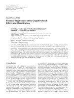
2.3. Single-digit 2DLNS inner product
computational unit
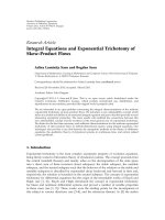
Figure 1 shows the structure of the single-digit 2DLNS inner
product computation unit (CU) from [3]. The multiplica-
tion is performed by small parallel adders for each of the
operands base exponents (top of the figure). The output
from the second-base adder is the address for an LUT or
ROM which produces an equivalent floating point value for
the product of the nonbinary bases (i.e., D
b
1
+b
2
≈ 2
ξ
B
·ξ
M
).
The base 2 exponents are added to that of the table to
provide the appropriate correction to the subsequent barrel
shifter (i.e., 2
a
1
+a
2
D
b
1
+b
2
≈ 2
a
1
+a
2
+ξ
B
·ξ
M
). This result may
then be converted to a 2’s complement representation, set
to zero, or unmodified based on the product of the signs
of the two inputs (
−1, 0, or 1, resp.). The final result
is then accumulated with a past result to form the total
accumulation (i.e., y(n +1)
= y(n)+2
a
1
+a
2
+ξ
B
·ξ
M
).
This structure removes the difficult operation of addi-
tion/subtraction in 2DLNS by converting the product into
binary for simpler accumulation. It is best for feedforward
First-base
exponents
Second-base
exponents Signs
a
1
a
2
b
1
b
2
s
1
, s
2
+/− +/−
Look-up table
Exponent Mantissa
+/
−
ξ
B
ξ
M
Barrel
shifter
Sign
corrector
Binary input
Binary output
+/
−
Figure 1: One-digit 2DLNS inner product computational unit from
[3].
architectures. We note that when the range of the second-
base exponent, R, of the 2DLNS representation is small (e.g.,
less than 4 bits), then these LUTs will be very small as well.
Thestructurecanbeextendedtohandlemorebasesby
concatenating the output of each corresponding exponent
adder to generate the appropriate address for the LUT. The
penalty however is that every extra address bit doubles the
LUT entries. The structure itself will be replicated depending
on the number of digits. If both operands have the same
number of digits, we can expect to have n
2
such units in an
n-digit MDLNS. For a parallel system, these outputs could
be summed at the end of the array using an adder tree for
example. The biggest advantage of the use of more than
one digit for the operands is that one can obtain extremely
accurate representations with very small exponents on the
second base. But the area cost increases as the number of
computational channels required is increased to at least four.
3. SELECTING AN OPTIMAL BASE
3.1. The impact of the second base on hardware
A closer look into the architecture above shows that the LUT
stores the floating-point-like representation of the powers
of the second base D. The area complexity depends almost
entirely on the size of the LUT which is determined by
the range of the sum of the second base-exponents, b
1
and b
2
. Our main goal in selecting the second base is to
minimize, as much as possible, the size of the largest second-
base exponents used while maintaining the application
constraints. The actual value of D can be selected to
optimize the implementation without changing the overall
Roberto Muscedere 3
complexity of the architecture; in fact, as we will see, such an
optimization offers a great potential for further reductions
of the hardware complexity. Therefore, any value of D will
only change the contents of the LUT while the range of the
second-base exponents is the only factor which influences
the size of the LUT. The same can be said for the binary-to-
MDLNS converters found in [7]; their complexity is limited
by this range as well as the number of digits.
3.2. Defining a finite limit for the second base
We can limit the potential range of what could be considered
to be an optimal value by analyzing the unsigned single-digit
representation as shown in (3),
2
a
D
b
= 2
a−b
(2D)
b
= 2
a+b
D
2
b
. (3)
This expression shows that we can multiply or divide
the unknown base by any multiple of the first base there
changing its exponent but not changing the computational
result. This simple relationship implies a restriction on the
range of values of an optimal base. For example, if our search
was to begin at D
= 3, then it would be pointless to go
outside of the range 3 to 6 as the results of the representation
would simply repeat.
Therelationshipin(3) also shows that as the value of
D is divided by a multiple of 2, the exponent of the first
base will increase when b is positive but decrease when
b is negative. A similar conclusion can be made for the
case when D is multiplied by a multiple of 2. Therefore,
some representations may have large values for the first base
exponent, and some may have smaller values. For a hardware
implementation, the bit-width of the first base exponent
should be minimized while maintaining the selected repre-
sentation space. We can determine the bit-width for the first
base exponent by limiting our representation with (4),
1
≤ 2
a
D
b
< 2. (4)
There is a unique first base exponent for every second-
base exponent. We continue by taking the logarithm of (4)
as shown in (5),
0
≤ a ln(2) + b ln(D) < ln(2). (5)
From (5), we obtain limits on the first base exponent, as
shown in (6),
−b
ln(D)
ln(2)
≤ a<1 − b
ln(D)
ln(2)
. (6)
Since the range of b is known, the value of a can be found
for all valid values of b. From this, the integer range of a can
be found from the maximum and minimum values of b.The
binary word length of the usable 2DLNS range is added to the
maximum integer range of a to find the total range of a.For
example, if D
= 3andb ranges from −4 to 3 (4 bits), then the
range for the first base exponent will be between
−4and7for
numbers between 1 and 2. If we wish to represent at most a 9-
bit integer, then we will require a range of [
−4, (7 +9 = 16)]
for the first base exponent, or 6 bits.
Using these relationships, we can potentially reduce the
number of bits required to represent a.From(6), the range
of a depends on the factor ln(D)/ ln(2), where minimizing
ln(D) results in a smaller bit-width on a. Since the factor has
a denominator of ln(2), any integer multiple of 2 on D will
produce the same 2DLNS results. The function ln(D)willbe
minimized when D is closest to 1. The optimal range of D can
thus be found by relating ln(y)(whichis>1) with ln(y/2)
(which is <1). Setting ln(y)
=−ln(y/2), we obtain y =
√
2.
Therefore, the optimal range of D is between
√
2/2(or1/
√
2)
and
√
2. We now have established an optimal range for D that
will provide a minimal bit-width to represent the first base
exponent, a and eliminate base replication.
If we rework our previous example using D
= 0.75 (3
divided by 4) and set the range of b to [
−4, 3] (4 bits), the
range for the first base exponent will be between
−1and2.
To represent a maximum of a 9-bit integer, we will require
arangeof[
−1, (2 + 9 = 11)] for the first base exponent,
or 5 bits. This is a saving of 1 bit from the previous example,
where D
= 3, but with no change in the representation.
3.3. Finding the optimal second base
We have developed two methods for determining the optimal
base for m numbers in the set x. The first, an algorithmic
approach, only applies to single-digit 2DLNS, and the
second, a range search, applies to any number of digits.
3.3.1. Algorithmic search
Using the assumption that the optimal base represents one
of the values in the given set x with virtually no error (ε
∼
=
0), then that optimal base can be found by solving the base
from the single-digit unsigned 2DLNS expression as in the
following:
D
=
b
x
2
a
or D = x
1/b
2
−a/b
. (7)
This expression can be solved for every value in the
set x given the range on b which depends on R (i.e., b
=
{−
2
R−1
, , −1,1, ,2
R−1
− 1}). Since any multiple of 2 on
D does not effect the 2DLNS representation, a is limited
by b, such that a
={−b +1, , b − 1}. Although many
solutions may exist depending on the value of R and the
number of values x, only the bases with the smallest errors
will be finely adjusted until the final optimal base is found
(see Section 3.3.3).
3.3.2. Range search
A second alternative is to perform a range search through all
the possible real bases. We have already seen that the most
efficient bases for hardware implementation lie in the range
[1/
√
2,
√
2]. This limitation offersapracticalstartandend
point for a range search. Given an arbitrary second base,
the program measures the error of mapping the given set
x into a multidigit 2DLNS representation. The possible rep-
resentation methods can reflect those of hardware methods
available such as the greedy/quick, high/low approximations
4 EURASIP Journal on Advances in Signal Processing
[7] or a brute force approach. The program uses a dynamic
step size which is continuously adjusted by analyzing the
change in the mapping errors for a series of test points.
This step size increases so long as the resulting errors are
monotonically improving. If this is not the case, the program
retraces and decreases this step size. When a better error is
found it is added to a running list of optimal candidates.
Using a dynamic step size is effective in finding optimal base
candidates while also reducing the overall search time. Once
the entire range has been processed, each element in this list
is finely adjusted. Depending on the representation method
selected and the range of R, this approach can generate fewer
bases than the algorithmic method and therefore produce
results in a shorter amount of time.
3.3.3. Fine adjustment
A fine adjustment is performed with the list of optimal
candidates by progressively adding and subtracting smaller
and smaller values. The performance of the software is
further increased by using direct floating point (IEEE 64-bit)
manipulation as well as minimizing conditional branches
and expensive function calls. This approach drastically
improves search times by initially performing a coarse search,
by one of the methods above, and then a finer search near the
selected optimum points.
4. ONE-BIT SIGN ARCHITECTURE
The data path of the 2DLNS processor (in Figure 1)is
affected significantly by the signs of the operands. The
required sign correction operation comes at a cost of addi-
tional logic and power. Thus far, a multidigit architecture
would require additional processing to be performed after
the 2DLNS processor, such as summing all the channels.
It is possible to use the common one-bit sign binary
representation for the intermediate results. We have therefore
developed a new 2DLNS sign system to reduce the processing
path of the 2DLNS inner product CU while producing a
single sign-bit binary representation.
4.1. Representation efficiency
Our original 2DLNS notation uses two bits to represent the
sign for each digit (
−1, 0, and 1) however only three of four
states are used, one of which (zero) only represents a single
value. By using two bits for the sign, the efficiency of the
representation is approximately 50 percent:
efficiency
two-bit sign
=
valid representations
total possibilities
=
2
1+B+R
+1
2
2+B+R
∼
=
0.5.
(8)
To improve this efficiency, we propose that only a single
sign-bit is needed to represent the most common cases,
that is,
−1 and 1. We then choose to represent zero by
setting the second-base exponents to their most negative
values (i.e., if the range is [
−4, 3], then −4 is used to
represent zero). This allows us to reduce the circuitry of
the system while maintaining the independent processing
paths of the exponents; this modification is easily integrated
into the existing two-bit sign architecture. This special case
for zero still leaves us with a significantly smaller unused
representation space compared to the two-bit sign system. As
R increases, the valid representations ratio approaches 1:
efficiency
one-bit sign
=1−
invalid representations
total possibilities
=1−
2
1+B
2
1+B+R
=
2
R
− 1
2
R
−→ 1.
(9)
With the one-bit sign system, the range of the second base
changes to b
i
={−2
R−1
+1, ,2
R−1
− 1} with a special case
of b
i
=−2
R−1
representing zero.
4.2. Effects on determining the optimal base
Since the upper and lower bounds of the second-base
exponent are equal in magnitude, this eliminates the need for
any reciprocal computations in determining the optimal base
(i.e., D
b
= 1/D
−b
) thus approximately halving the search
time for both algorithms. For the algorithmic search, the
possible range of b is changed, such that b
={1, ,2
R−1
−1}.
For the range search approach the second base limits are now
([ 1/
√
2, 1.0]or[1.0,
√
2 ]).
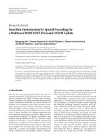
4.3. Effects on hardware architecture
By using the one sign-bit architecture, the word length for
any 2DLNS representation is reduced by 1 bit per digit.
Compared to the original CU, we can remove the sign cor-
rector component (essentially a conditional 2’s complement
generator). The sign is calculated by simply XORing the two
signs of the inputs. The output is now only an absolute binary
representation which can easily be manipulated further with
the sign bit depending on the number of digits (see Figure 2).
The special zero case only needs to be handled by modifying
the very small adders in the multiplication component; the
representation of zero is now inside the table and therefore
eliminates the conditional path.
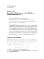
To accumulate this result with any other value, we can
use the generated sign bit to determine the proper operation
of an addition/subtraction component (see Figure 3). The
inclusion of a one-bit sign allows us to reduce the hardware
and computational path by removing the zero/two’s comple-
ment generator. The final adder/subtractor component itself
is slightly larger than an adder, but with regards to the whole
system, this architecture will consume less area and time.
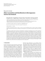
In the case of a two-digit 2DLNS system, the accumula-
tion of the four output channels can be simplified with the
one-bit sign by using only 3 adder/subtractor components
and simple logic to coordinate the proper series of operations
(see Figure 4). The processing delay from the LUTs is only 3
arithmetic operations and the overall logic is also reduced
since the 3 adder/subtractor components are smaller than
the 3 separate adders and four 2’s complement generator
components present in the original CU. This approach was
Roberto Muscedere 5
First-base
exponents
Second-base
exponents Signs
a
1
a
2
b
1
b
2
s
1
, s
2
+/−
+/−
Look-up table
Exponent Mantissa
Barrel
shifter
Absolute
output
Sign bit for
accumulation
+/
−
Figure 2: One-bit sign 2DLNS inner product computational unit.
Absolute input Sign bit
+/
−
Binary output
Binary input
Figure 3: Single-digit one-bit sign accumulation component.
used in [6] and showed a 55% saving in power as well
as other improvements compared to the original design in
[8]. Further hardware reductions can be made by ordering
each 2DLNS processor in order of product magnitude. The
resulting binary representation will be the largest for the first
channel but will be decreased for each of the subsequent
channels. If the range of both operands is known, the
mantissa in the LUTs can be sized correctly as well as the
subsequent adders.
5. EXAMPLE FINITE IMPULSE RESPONSE FILTER
To demonstrate how important it is to choose an optimum
base, D, we provide the following example of a 47-tap
lowpass FIR filter. There are many methods for designing
digital filters, each of which prioritizes different output
characteristics. In our case, we will use a simple set of
characteristics which generalizes the problem so that the
proposed method can be applied to any other application.
For this example, we will minimize the passband ripple
(<0.01 dB), maximize the stop band attenuation, and main-
tain linear phase (the coefficients will be mirrored in order
to guarantee linear phase). To further reduce the complexity
of this problem, we will first generate the filter coefficients by
using classical design techniques. Ideally, using floating point
values, we obtain a passband ripple of 0.0008 dB and a stop
band attenuation of 81.1030 dB (see Figure 5).
Sign
bits
Absolute channels
Sign
bits
as1
as2
ach1 ach2 ach3 ach4
as3
as4
as1
as3
as1
+/
− +/−
Binary input
+/
−
Binary output
+/
−
Figure 4: Two-digit one-bit sign accumulation component.
−150
−125
−100
−75
−50
−25
0
Magnitude (dB)
00.20.40.60.81
Normalized frequency (
×π rad/sample)
Figure 5: Magnitude response of the 47-tap FIR filter; ω
p
= 0.4and
ω
s
= 0.6.
We will compare the results between a standard base
of 3 as it has been used often in other published work.
We could use any arbitrary base and the results would
be similar. Once we have the real FIR filter coefficients,
we then map them into a 2DLNS representation. If our
mapping is poor, we can expect equally poor stop band
attenuation as well as passband ripple, whereas a more
accurate mapping will result in better filter performance.
We choose not to calculate the filter’s performance during
the calculation of the optimal base, but rather the absolute
error in the mapping itself. This improves the performance
of the optimal base calculation and allows the process to
be used with any filter design techniques or even for other
applications entirely. Note that we do not impose restrictions
on the size of the binary exponents as they have very little
contribution to the overall complexity of the architecture.
We require, however to know what their range will be for
hardware implementation. An FIR filter basically multiplies
a series of “data” values (from some external source) to
asetoffilter“coefficients” to generate an “output;” these
terms will be used throughout the rest of this design. Since
6 EURASIP Journal on Advances in Signal Processing
20
30
40
50
60
70
Stop band attenuation (dB)
0.70.75 0.80.85 0.90.95 1
Base
Figure 6: Stop band attenuation for bases 0.7071 to 1.0000 for r
c
=
63; worst case is 15.0285 dB, best case is 72.0858 dB.
0
50
100
150
200
250
Number of bases (total = 2930)
20 30 40 50 60 70
Stop band attenuation (dB)
Figure 7: Histogram of stop band attenuation for bases 0.7071 to
1.0000.
we are discussing the 2DLNS representations of the data,
coefficient and product values in the same system, we will
refer to their exponents as (a
d
, b
d
), (a
c
, b
c
), and (a
o
, b
o
),
respectively. We will also compensate for a finer resolution
on the multiplicands such that b
d
={−r
d
, , r
d
} and b
c
=
{−
r
c
, , r
c
} resulting in a product where r
o
= r
d
+ r
c
and
b
o
={−r
o
, , r
o
}. The range of the products second-base
exponent, b
o
, will dictate the complexity of the system.
To demonstrate how any arbitrary base can affect the
filters performance, we have mapped the coefficients into a
single-digit 2DLNS using bases between 1/
√
2and1.0(in
increments of 0.0001) and plotted the resulting stop band
attenuation in Figure 6 for r
c
= 63.
This figure clearly shows that there is no obvious
correlation between the filter’s performance and the choice
of the second base; in fact it appears random. The same can
be said for the passband ripple. We can also examine these
results in the form of a histogram as in Figure 7.
The low values of the stop band attenuation are a result
of bases very close to 1.0 (where, as the exponent increases,
the normalized representation approaches 1). The average
is 54.6721 dB, but for a base of 3 (or 0.75) it is 61.0460 dB;
which is better than the average results. Even though, our
sample size for this test is small (2930 values), it is reasonable
to assume that any arbitrary base will not give the best
2DLNS representational performance. The best base in this
case is 0.8974 with a stop band attenuation of 72.0858 dB.
This is a good result but it is possible to achieve better
without testing the filter’s performance for every possible
base.
5.1. Optimizing the base through
analysis of the coefficients
Generally the signal samples or input “data” are large in
magnitude and in order to accommodate for this, we will
need to use two or more digits for their representation. If
the input data was relatively small, we could use a one-digit
representation, however we would expect some quantization.
For our example, we will use a two-digit representation as the
intended input range is larger (
−32768 to 32767 or 16 bits).
5.1.1. Single-digit coefficients
In [9], the typical distribution of the coefficients of many
different filters was found to be a Gaussian-like function
centered on zero. Such a coefficient distribution is better
represented by a logarithmic-like number system (such as the
LNS or 2DLNS) rather than a linear number representation
(such as binary). Therefore, we should be able to obtain
very good single-digit approximations in the 2DLNS by
making use of a carefully calculated second base. Since the
data representation uses two digits, the resulting system
will consist of only two computational channels. We will
also consider a two-digit 2DLNS representation with four
channels later.
A comparison of the frequency response for a wide range
of exponent ranges (or various values of r
c
) for the example
filter is shown in Ta bl e 1 . We compare the passband ripple
and stop band attenuation within a system with the second
base of 3 and an optimal base. The optimal base is truncated
to 6 decimal digits for presentation, however, the number of
decimal digits is computed up to 15 (IEEE 64-bit floating
point) and may be very necessary when the exponents on the
base are large.
The table shows that as r
c
increases, we can save up to two
bits on the second-base exponent by using an optimal second
base rather than 3. The size of the second-base exponent
plays an important role in the size of the hardware due to
the required LUTs; any 1-bit increase to any nonbinary base
exponent doubles the LUT size, whereas an increase in the
binary exponent adds minimal hardware. Any change to the
second base, including real numbers has no impact on the
structure of the hardware. Therefore, hardware designed for
a second base of 3 is easily converted to use the optimal base
as we are only changing the contents of the tables and not
Roberto Muscedere 7
Table 1: Filter performance for ternary and optimal base (single-digit).
r
c
Base 3 Optimal base
Passband ripple (dB) Stop band attenuation (dB) Passband ripple (dB) Stop band attenuation (dB) Base
1 0.5147 24.2840 0.1498 35.3497 0.793123
3 0.2644 30.1926 0.0518 44.5401 0.889553
7 0.0526 44.3046 0.0202 52.5938 0.888477
15 0.0195 52.8771 0.0053 64.4114 0.897501
31 0.0131 56.5177 0.0031 68.5123 0.897504
63 0.0079 61.0460 0.0014 74.6231 0.788051
127 0.0034 68.7088 0.0010 77.6842 0.908324
255 0.0020 73.4312 0.0010 80.0042 0.876152
Table 2: Filter performance for ternary and optimal base (two-digit).
r
c
Base 3 Optimal base
Passband ripple (dB) Stop band attenuation (dB) Passband ripple (dB) Stop band attenuation (dB) Base
1 0.0314 48.8313 0.0013 76.8648 0.757910
2 0.0042 66.4051 0.0010 78.6542 0.899757
3 0.0031 68.9081 0.0009 80.0583 0.957323
4 0.0020 73.0290 0.0008 80.3113 0.789982
5 0.0016 74.9437 0.0008 80.9408 0.814313
6 0.0016 74.7669 0.0008 81.0408 0.919486
7 0.0015 75.4867 0.0008 81.0342 0.885619
their dimensions. In this case a two-bit reduction translates
to a 4X area saving per LUT or CU.
5.1.2. Two-digit coefficients
We will continue using a two-digit representation for the
signal and now use a two-digit representation for the
coefficients. This will result in 4 parallel computational
units. The method for generating these representations is
via a brute force approach where effectively all possible
representations are generated and the one with the least
error is chosen. This method is not applicable to hardware
as it is assumed; the coefficients will be generated offline.
This approach was taken in [8] to improve 8 separate FIR
filters in a filter bank application. Another comparison of the
frequency response for various values of r
c
is shown for the
two-digit coefficients in Tab le 2 .
We st op a t r
c
= 7 as the results are approaching near
ideal. Again the use of an optimal second base offers the same
stop band attenuation as with a second base of 3 but with two
fewer bits. This saving is important as the CU in this case is
duplicated four times.
5.1.3. Comparison of single and two-digit coefficients
In order for a one-digit 2DLNS to achieve 80dB stop
band attenuation, we need to use 9 bits (r
c
= 255) for
the second-base exponents and, correspondingly, we require
an LUT with 512 entries for each CU (two for a parallel
implementation). For a two-digit 2DLNS, we only need 3 bits
(r
c
= 3) to represent the second-base exponents therefore
requiring an LUT with 8 entries for each CU (four for a
parallel implementation). The two-digit coefficient system
appears to be favorable as the LUTs are smaller; however,
there is some additional overhead in the accumulation circuit
for all the channels. It is also very important to note that this
entire 4-channel architecture is multiplier-free as it consists
only of small adders and very small LUTs.
5.1.4. Effects on the two-digit data
Clearly the choice of the second base has a significant effect
on the performance of the filter. However, in order to use
this representation effectively, we have to apply the same
second base to the data representation or input signal as well
in order for the 2DLNS arithmetic to operate properly. In
the case of filter design, our optimal base is selected by the
filter’s performance which we can relate back to the quality
of the mapping. In the case of data, specifically integers, we
do not necessarily require perfect mapping but only error-
free representations where, from (1), ε is less than half a bit
or 0.5 [1]. Ta bl e 3 shows the range of r
d
for a 0%, 1%, 5%,
and 10% nonerror-free representations with a base of 3 and
the optimal bases from Tables 1 and 2,respectively.
We can see that the optimal base for the best filter
performance is not ideal for data mapping as r
d
,onaverage,
must be in the hundreds. When applying the optimal base
to the coefficients, the performance increases as r
c
increases.
There is no correlation here as the base was chosen only for
optimal mapping of the coefficients. The case where r
d
= 886
in particular is unusual as this base produces bitstreams with
long sequences of ones or zeros when the exponent exceeds 1.
8 EURASIP Journal on Advances in Signal Processing
Table 3: Data representation performance for various bases
Base
Error free 1% nonerror-free 5% nonerror-free 10% nonerror-free
r
d
r
d
Wor st εr
d
Wor st εr
d
Wor st ε.
3.000000 93 51 0.898 28 1.272 24 2.533
0.793123 147 131 1.867 113 17.349 101 28.392
0.889553 71 36 1.213 32 4.452 30 5.976
0.888477 70 48 1.002 35 1.872 27 2.009
0.897501 59 44 1.290 34 2.435 28 2.438
0.897504 54 45 1.330 35 2.437 29 2.522
0.788051 105 74 1.189 55 1.858 42 2.308
0.908324 66 47 1.364 36 1.720 29 2.121
0.876152 74 59 1.511 46 2.763 39 4.009
0.757910 886 734 6.002 566 18.941 496 25.501
0.899757 52 40 0.994 28 1.605 24 2.476
0.957323 67 54 1.810 45 3.238 39 3.678
0.789982 70 45 1.235 29 1.414 23 2.565
0.814313 270 191 1.252 134 2.206 106 2.944
0.919486 95 70 1.106 50 1.707 39 2.636
0.885619 48 40 1.442 30 1.545 25 2.751
5.2. Optimizing the base through analysis of the data
We have seen how applying an optimal base to the coeffi-
cients of a digital filter can significantly increase the accuracy
of the 2DLNS representation. This same improvement can be
seen when applied to the input data of the filter. For the case
of a 16-bit signed input, from
−32768 to 32767, we require
r
d
= 39 in order to achieve a completely error-free mapping
using the high/low method [7] (the only published real-
time binary to MDLNS conversion circuit). For particular
applications however, a complete error-free mapping may
not be necessary. Ta b le 4 summarizes different choices of r
d
for nonerror-free integer mappings.
The trend of the number of nonerror-free representa-
tions follows an exponential decay as r
d
increases. From the
optimal base calculations of the coefficients (see Ta bl e 3),
we have the smallest r
d
of 36 with 1% nonerror-free
representation but with a worst case error of 4.452. The next
smallest r
d
of 40 offers a worst case error of only 0.994.
Both cases require r
d
to be increased by more than 33% to
achieve an error-free representation. When optimizing the
base for the data representation, we can select r
d
= 32 to
achieve less than 1% nonerror-free representation with a
worst case ε of 0.772. This is comparable to r
d
= 40 in Tab le 3
but with a 25% reduction in the exponent range as well as
the LUT entries. This approach was used in [6] so that the
filter coefficients could be changed by mapping them into
the optimal base selected for the data representation. This
required a larger r
c
to improve the filter performance, but
allowed the coefficients to be runtime loaded.
5.3. Optimizing the base through analysis of both
the coefficients and data
We have so far seen that an optimal base can improve
the coefficient or data representations of a 2DLNS filter
architecture without changing the range of the exponents.
Again, the 2DLNS arithmetic will not operate correctly
unless both bases are the same. In each case the selection
of one base severely impacts the other’s representation. To
remedy this, we have modified the optimal base software to
target two separate scenarios. This is done by optimizing the
two independent sets of values and minimizing the product
of their errors.
5.3.1. Single-digit coefficients and two-digit data
For our example of an FIR filter, the data is represented
with two-digit 2DLNS (using the high/low method) and the
coefficients with a single-digit (later, two-digit brute-force
method). Since the range of r
c
must be large for the single-
digit coefficients to obtain good filter performance, we will
also target an error-free data mapping as we can expect that
r
d
will be close to 39. Through experimenting with different
variations of r
d
, it was found that r
d
would have to be 42
in order to produce an error-free data representation. To
maximize the data path utilization for r
o
, the remaining bits
are used to specify r
c
; this technique has been virtually used
in every DBNS/MDLNS paper to date. Tab le 5 shows the best
results of the optimal base calculations for 8 (42 + 85
= 127)
and 9 (42 + 213
= 255) bits. The resulting passband ripple
is no longer presented on this or subsequent tables as it is
always below the specification of 0.01 dB. The bolded values
in the table indicate the best result for the selected attribute.
A bolded base is the author’s choice for best stop band
attenuation, nonerror-free representations, and the worst
case error.
5.3.2. Comparison to the individual optimal base
Comparing the filter performance results of Tables 1 to
5, we can see approximately a 2 dB reduction in the stop
Roberto Muscedere 9
Table 4: Data representation performance for optimal bases.
Base r
d
Nonerror-free representations Worst ε %Nonerror-free
0.810537 16 16472 2.933 25.13
0.853451 17 14296 2.857 21.81
0.844819 18 12406 2.362 18.93
0.867483 19 10926 2.156 16.67
0.776015 20 9238 1.991 14.10
0.797969 21 7836 1.717 11.96
0.769616 22 6630 1.598 10.12
0.915321 23 5566 1.540 8.49
0.855890 24 4594 1.333 7.01
0.838039 25 3746 1.343 5.72
0.987020 26 3020 1.231 4.61
0.797037 27 2398 1.104 3.66
0.843455 28 1854 1.061 2.83
0.719670 29 1394 1.001 2.13
0.815027 30 1082 0.906 1.65
0.785026 31 766 0.845 1.17
0.749814 32 558 0.772 0.85
0.710762 33 348 0.822 0.53
0.843007 34 216 0.712 0.33
0.990287 35 144 0.684 0.22
0.892307 36 74 0.636 0.11
0.854608 37 36 0.610 0.05
0.756487 38 16 0.569 0.02
0.735582 39 0 — 0.00
Table 5: Combined optimal base (single-digit coefficient, two-digit data).
r
d
r
c
Base Stop band attenuation (dB) Nonerror-free representations Worst ε %Nonerror-free
42 85 0.924440 75.5074 348 0.993 0.53
42 85 0.871988 68.7626 0 —0.00
42 85 0.815959 75.1871 88 0.756 0.13
42 213 0.912396 78.2265 196 0.839 0.30
42 213 0.872018 77.2010 0—0.00
band attenuation. However, comparing the nonerror-free
data mapping to Ta bl e 3 ,wecanseealargeimprovement
in the representation. This improvement seems to justify the
sacrifice of 2 dB in the stop band.
When considering a hardware implementation, r
o
will
never exceed
±255 for the 9-bit system. The 2DLNS-to-
binary conversion tables will require 2r
o
+ 2 entries, one of
which is for the zero representation. We will therefore have
two inner product CUs each containing tables of 512 entries
totaling 1024 entries for both CUs.
5.3.3. Two-digit coefficients and two-digit data
We can also apply the blended optimal base to the two-digit
coefficient representation as well. Since the ranges on r
c
are
much smaller, we will explore the possibility of having a
nonerror-free data representation. As we have seen before,
obtaining an error-free data representation will require larger
ranges of r
d
which in turn will require larger tables for
the 4 parallel inner product CUs. Ta bl e 6 shows various
possibilities for r
d
and r
c
.
Initially 28 and 3 are chosen to maximize the bit width of
the product exponent b
o
, but the data representation is poor
when the filter’s performance is high. As we increment r
c
,we
can see an increase of about 0.5 dB for the best case stop band
attenuation. We settle on r
c
= 5 as the best case stop band is
approximately 80 dB. As we increment r
d
, we see a similar
exponential decay trend as before when only optimizing for
the data. In the cases of maximum stop band attenuation,
the number of nonerror-free representation is quite high.
This drops considerably when we sacrifice a little in the stop
band (
∼0.1 dB). We can begin to reach an error-free data
10 EURASIP Journal on Advances in Signal Processing
Table 6: Combined optimal base (two-digit coefficient, two-digit data).
r
d
r
c
Base Stop band attenuation (dB) Nonerror-fee representations Worst ε %Nonerror-free
28 3 0.895008 79.9529 23910 4.972 36.48
28 3 0.941001 66.9800 1908 1.000 2.91
28 3 0.737860 77.5315 2048 1.115 3.13
30 4 0.858929 80.4562 4794 1.924 7.32
30 4 0.796725 71.2290 1062 0.932 1.62
30 4 0.862663 75.2993 1116 0.875 1.70
30 4 0.745462 80.3739 1636 1.162 2.50
31 4 0.858929 80.4562 4398 1.924 6.71
31 4 0.711017 69.9018 828 0.824 1.26
31 4 0.745462 80.3739 1534 1.162 2.34
33 5 0.814313 80.9394 19074 3.901 29.10
33 5 0.764157 75.2038 394 0.802 0.60
33 5 0.989748 75.1037 426 0.738 0.65
33 5 0.816596 80.5589 568 0.854 0.87
34 4 0.858929 80.4563 3348 1.571 5.11
34 4 0.777919 72.8959 246 0.715 0.38
34 4 0.777915 75.5193 284 0.693 0.43
34 4 0.790987 79.2613 334 0.741 0.51
39 5 0.738251 80.9350 10806 5.512 16.49
39 5 0.710235 76.9878 4 0.536 0.01
39 5 0.722788 75.8355 12 0.516 0.02
39 5 0.732693 80.4818 24 0.570 0.04
40 5 0.816596 80.5634 532 0.842 0.81
40 5 0.710131 72.6561 0 —0.00
40 5 0.974939 80.2883 72 0.781 0.11
41 5 0.915757 80.6101 738 0.854 1.13
41 5 0.746550 77.9541 0 —0.00
41 5 0.938171 80.0786 36 0.615 0.05
42 5 0.974939 80.4183 12 0.588 0.02
42 5 0.944509 78.6000 0 —0.00
representation when r
d
= 40 and above. Depending on
the application, a nonerror-free mapping may be acceptable
considering the worst case ε is below 1.0.
5.3.4. Comparison to the individual optimal base
When we compare the above results with the previous
individual optimal bases, we can see that we have not
sacrificed much in terms of stop band attenuation (r
c
= 5) or
exponent ranges for error-free data mapping (r
d
= 40). This
approach seems to offer the best filter performance and data
representation as compared to the single-digit coefficients.
For the purposes of implementation, r
o
will never exceed
±45. We can therefore expect to have four inner product
CUs, each of which with 92 entries, totaling 368 entries for
four CUs.
5.4. Comparison of base 3 to the optimal bases
There are many possibilities available for an optimal base
depending on the accuracy required for the filter per-
formance and data representation. Ta bl e 7 compares the
original base 3 and optimal base system’s performance to
give at least 73 dB stop band attenuation and a 0% and 1%
nonerror-free data mapping. For all cases, the optimal base
offers saving in the CU LUTs as well as the range of the
second-base exponent.
In the single-digit case, we can increase or decrease r
d
to decrease or increase the nonerror-free representations,
respectively.
5.5. Comparison to general number systems
We have thus far only shown the improvement in the
2DLNS representation and circuit resources when applying
an optimal base compared to the legacy base of 3. We
can further compare the above results with those from
common general number systems, such as fixed-point and
floating-point binary as well as a fixed-point exponent LNS,
which are traditionally used in physical implementations.
Ta bl e 8 shows a summary of the example filter’s performance
using these number systems for 1 to 20 bits. Note that the
Roberto Muscedere 11
Table 7: Comparison of standard and optimal base for a minimum 73 dB system.
Base Stop band attenuation (dB) % Nonerror-free r
c
r
d
LUT entries per CU Total LUT entries
Single-digit coefficients
3.000000 73.4312 1.00 255 51 614 1228
0.828348 73.7272 0.67 85 39 250 500
Saving 59.3%
3.000000 73.4312 0.00 255 93 698 1396
0.828348 73.7272 0.00 85 45 262 524
Saving 62.5%
Two-digit coefficients
3.000000 75.4867 1.00 7 51 118 472
0.777915 75.5193 0.43 4 34 78 312
Saving 33.9%
3.000000 75.4867 0.00 7 93 202 808
0.746550 77.9541 0.00 5 41 94 376
Saving 53.5%
Table 8: Comparison of filter performance for general number systems.
Bits
Fixed-point binary Floating-point binary LNS with fixed-point exponent
Passband ripple
(dB)
Stop band
attenuation
(dB)
Passband ripple
(dB)
Stop band
attenuation
(dB)
Passband ripple
(dB)
Stop band
attenuation
(dB)
1
6.0206 6.0206 1.4225 16.4174 2.2454 14.6224
2
3.6810 9.2326 1.2905 17.1989 1.3542 26.0100
3
3.6810 9.2326 0.1589 34.8402 0.5313 28.6544
4
1.9997 13.7377 0.1521 35.2187 0.3403 37.1995
5
0.5606 24.0824 0.0813 40.6289 0.1493 38.1408
6
0.2873 29.7543 0.0693 42.0232 0.0776 45.6083
7
0.2474 31.0320 0.0092 59.6780 0.0422 54.1982
8
0.0778 41.0001 0.0036 68.0561 0.0249 69.0545
9
0.0507 44.6930 0.0025 71.3190 0.0127 71.2978
10
0.0211 52.2642 0.0026 70.9529 0.0064 74.0112
11
0.0117 57.4244 0.0019 74.1708 0.0032 74.8158
12
0.0062 62.9227 0.0017 75.2752 0.0017 74.7228
13
0.0040 66.8129 0.0016 75.5764 0.0012 78.0202
14
0.0023 71.6093 0.0012 78.7328 0.0009 80.0245
15
0.0013 76.5792 0.0009 80.9136 0.0008 80.8327
16
0.0012 77.2776 0.0009 80.6924 0.0008 80.9733
17
0.0010 78.6727 0.0008 81.0919 0.0008 81.0450
18
0.0008 80.2013 0.0008 81.0246 0.0008 81.1399
19
0.0008 80.7061 0.0008 81.1587 0.0008 81.1113
20
0.0008 81.1363 0.0008 81.1301 0.0008 81.1117
bit limitation is applied to the fractional portion of the
representations only. The integer portion (i.e., exponent for
floating point, integer for LNS exponent) is not considered as
it only affects the fixed-point binary representation for values
greater than 1; all of the filter’s coefficients are however less
than 1.
From Ta bl e 6, we achieved over 80 dB stop band
attenuation with only 6.6 bits per digit using a two-digit
data/coefficient system. In this case only 12 of the 65536
inputs have not any representation error, but it is less than
0.588. The LNS offers the best filter performance with 14
or more bits in the fractional exponent, however this choice
may come at the expense of a larger circuit for performing
binary-to-LNS-to-binary conversion with 14 fractional bits
as well as native LNS addition/subtraction, [10]forexample.
In terms of the data representation, all of the mentioned
general number system would require at least 14-15 bits to
represent an input integer with ε<1. For this example,
12 EURASIP Journal on Advances in Signal Processing
Ta bl e 7 shows that not more than 6.3 bits (per digit) are
required when using a two-digit 2DLNS representation (ε
≤
0.67). For each of these general number systems, additional
bits in the multipliers (or adders for LNS) will be required
to include the calculation of the input data. The presented
2DLNS approach does not need additional precision, but
the two-digit system does require an accumulation stage to
merge the results from the four separate processing channels.
The aforementioned improvements to 2DLNS with an
optimalbaseaswellasaone-bitsignmakethearchitecture
more attractive in applications where traditional number
systems such as fixed-point and floating-point binary as well
as LNS are used. Unfortunately, we are unable to explore
a 2DLNS in a wide variety of applications as the choice of
the second base is a balance of accuracy and implementation
hardware.
6. EXTENDING TO THREE BASES
Applying this software to find a set of optimal bases on a
multiple base system would have serious scalability issues as
we would be performing a linear search geometrically for
each base. The complexity of this problem can be considered
to be O(n
k
)wheren is the number of scenarios tested for
a single base, and k is the number of nonbinary bases. For
the two-digit coefficient case of r
d
= 40 and r
c
= 5, n is
20864199. The computational time for any scenario varies
considerably with r
d
, r
c
, and the representation method
selected, as they all effect the data generation and search
times. We do believe that it is possible to reduce this
massive search time for a single-digit 3DLNS system (two
nonbinary bases) by merging both algorithmic and range
searching methods. By assuming that one of the target
representations will have a near zero error, the algorithmic
search should provide a series of second bases with the
range search supplying the third base. We have yet to
attempt this process but we believe it can improve the single-
digit representation by using multiple bases with smaller
exponent ranges rather than a single base with a larger
exponent range. The complexity should be reduced as we
are effectively performing many two base optimizations
(potentially in parallel) but with a much smaller limitation
on the exponents. Using a 3DLNS system with smaller r’s
could result in a more compact hardware implementation
and better representation than a 2DLNS system.
7. CONCLUSION
Since the 2DLNS inner product computational unit requires
an LUT for 2DLNS-to-binary conversions, it is important to
try to minimize the size of this LUT as the overall system
complexity is based on it. We have shown, by example, that
selecting an optimal second base can reduce the size of these
LUTs and more importantly the range of b
o
, by a minimum
of 33% in one case without impacting the quality of the
2DLNS representation compared to the standard second
base of 3. These results should hold true for any other
arbitrary second base. As the binary-to-2DLNS conversion
hardware also depends on the range of the second-base
exponent, selecting an optimal base will offer reductions in
this component and may potentially reduce the data paths
and storage registers of the complete system. Reducing the
range of b
o
can also impact future architectures, one of which
would be a native MDLNS addition/subtraction circuit [11].
By migrating from a two-bit sign to a one-bit sign,
the computation time of the optimal base halves and the
hardware area and critical paths of published architectures
are further reduced as some processing steps are eliminated.
The software for finding an optimal base can be utilized
in many different applications other than FIR filter design.
The software accepts either a list of real numbers, a range of
integers, or both in order to find the best representation with
minimal error.
All software, source files, and detailed results can be
found at .
ACKNOWLEDGMENTS
This work was supported in part by the Natural Sciences
and Engineering Council (NSERC) of Canada, and Gennum
Corporation. The author would like to acknowledge the
important contribution of the Canadian Microelectronics
Corporation (CMC) for their equipment, and software loan.
REFERENCES
[1]V.S.Dimitrov,J.Eskritt,L.Imbert,G.A.Jullien,andW.C.
Miller, “The use of the multi-dimensional logarithmic number
system in DSP applications,” in Proceedings of the 15th IEEE
Symposium on Computer Arithmetic, pp. 247–254, Vail, Colo,
USA, June 2001.
[2] V. S. Dimitrov and G. A. Jullien, “Loading the bases: a new
number representation with applications,” IEEE Circuits and
Systems Magazine, vol. 3, no. 2, pp. 6–23, 2003.
[3] V. S. Dimitrov, G. A. Jullien, and W. C. Miller, “Theory
and applications of the double-base number system,” IEEE
Transactions on Computers, vol. 48, no. 10, pp. 1098–1106,
1999.
[4]M.G.Arnold,T.A.Bailey,J.R.Cowles,andJ.J.Cupal,
“Redundant logarithmic arithmetic,” IEEE Transactions on
Computers, vol. 39, no. 8, pp. 1077–1086, 1990.
[5]E.E.SwartzlanderJr.andA.G.Alexopoulos,“The
sign/logarithm number system,” IEEE Transactions on Com-
puters, vol. C-24, no. 12, pp. 1238–1242, 1975.
[6] R. Muscedere, V. Dimitrov, G. Jullien, and W. Miller, “A
low-power two-digit multi-dimensional logarithmic number
system filterbank architecture for a digital hearing aid,”
EURASIP Journal on Applied Signal Processing, vol. 2005, no.
18, pp. 3015–3025, 2005.
[7] R. Muscedere, V. Dimitrov, G. A. Jullien, and W. C. Miller,
“Efficient techniques for binary-to-multidigit multidimen-
sional logarithmic number system conversion using range-
addressable look-up tables,” IEEE Transactions on Computers,
vol. 54, no. 3, pp. 257–271, 2005.
[8] H. Li, G. A. Jullien, V. S. Dimitrov, M. Ahmadi, and W.
C. Miller, “A 2-digit multidimensional logarithmic number
system filterbank for a digital hearing aid architecture,” in
Proceedings of the IEEE International Symposium on Circuits
and Systems (ISCAS ’02), vol. 2, pp. 760–763, Scottsdale, Ariz,
USA, May 2002.
Roberto Muscedere 13
[9] J.Eskritt,R.Muscedere,G.A.Jullien,V.S.Dimitrov,andW.
C. Miller, “A 2-digit DBNS filter architecture,” in Proceedings
of IEEE Workshop on Signal Processing Systems (SiPS ’00),pp.
447–456, Lafayette, La, USA, October 2000.
[10] D. M. Lewis, “An architecture for addition and subtraction of
long word length numbers in the logarithmic number system,”
IEEE Transactions on Computers, vol. 39, no. 11, pp. 1325–
1336, 1990.
[11] R. Muscedere, “A hardware efficient single-digit 2-
dimensional logarithmic number system addition and
subtraction circuit,” submitted to IEEE Transactions on
Circuits and Systems.