Báo cáo hóa học: " Research Article Sum Rate Optimization by Spatial Precoding for a Multiuser MIMO DFT-Precoded OFDM Uplink" ppt
Bạn đang xem bản rút gọn của tài liệu. Xem và tải ngay bản đầy đủ của tài liệu tại đây (1.37 MB, 12 trang )
Hindawi Publishing Corporation
EURASIP Journal on Advances in Signal Processing
Volume 2011, Article ID 927936, 12 pages
doi:10.1155/2011/927936
Research Ar ticle
Sum Rate Optimization by Spatial Precoding for
a Multiuser MIMO DFT-Precoded OFDM Uplink
Hanguang Wu,
1
Thomas Haustein (EURASIP Member),
2
Eduard Axel Jorswieck
(EURASIP Member),
3
and Peter Adam Hoeher
4
1
mimoOn GmbH, Bismarckstraße 120, 47057 Duisburg, Germany
2
Fraunhofer-Institute for Telecommunications, Heinrich-Hertz-Institute, Einsteinufer 37, 10587 Berlin, Germany
3
Communications Laboratory, Dresden University of Technology, 01062 Dresden, Germany
4
Faculty of Engineering, University of Kiel, Kaiserstraße 2, 24143 Kiel, Germany
Correspondence should be addressed to Hanguang Wu,
Received 15 October 2010; Revised 31 January 2011; Accepted 10 February 2011
Academic Editor: Robert Fischer
Copyright © 2011 Hanguang Wu et al. This is an open access article distributed under the Creative Commons Attribution License,
which permits unrestricted use, distribution, and reproduction in any medium, provided the original work is properly cited.
By means of DFT-precoding, the PAPR of OFDM waveforms can be reduced. DFT-precoding has been proposed for uplink
transmission in various future wireless communication systems. In this work, we consider DFT-precoding combined with spatial
precoding for the uplink of multiuser MIMO OFDM systems. An efficient algorithm is developed to optimize the spatial precoder
aiming at maximization of the system sum rate subject to individual power constraints of the users and maintenance of the
low PAPR property for one user. Potential gains are shown compared to other popular precoding methods in 3GPP-LTE uplink
scenarios.
1. Introduction
Over the last years, the demand for high data rates has
increased significantly. This has led to the use of wider trans-
mission bandwidth and MIMO (Multiple-Input Multiple-
Output) techniques. In a cellular environment and especially
at large transmission bandwidth, the channel between the
antennas at the transmitter and receiver becomes increas-
ingly frequency selective. OFDM (Orthogonal Frequency-
Division Multiplex) with its multiple access scheme OFDMA
(Orthogonal Frequency-Division Multiple Access) is consid-
ered as a strong candidate for wideband transmission due
to its robustness against frequency selective fading and low-
computational complexity for channel equalization using
frequency domain equalization (FDE) [1]. However, a major
drawback of OFDM(A) is that its transmit waveform has
a high peak-to-average power ratio (PAPR). In order to avoid
the transmitted signal going into the nonlinear region of the
power amplifier, the mean input power has to be limited or
backed off to a certain value roughly corresponding to the
PAPR (in decibel) of the transmitted waveform. Therefore,
high PAPR is power inefficient, especially problematic for cell
edge users to be able to overcome the large path loss to reach
their serving base station (BS) in uplink transmission.
Various PAPR reduction techniques have been proposed
for OFDM systems. A good overview of those techniques is
addressed in [2] and the references therein. Among others,
DFT-precoding is an attractive solution without requiring
any additional signalling overhead. Especially, with low-
order modulation schemes like BPSK and QPSK, signifi-
cantly lower PAPR compared to that of OFDM without
precoding is possible [3]. Recently, multiple access schemes
based on DFT-precoded OFDM(A) are adopted for uplink
transmission in various future mobile communication sys-
tems. For example, the 3rd Generation Partnership Project
(3GPP) employs DFT-precoded OFDMA with localized sub-
carrier allocation (LFDMA) [4] for the Long-Term Evolution
(LTE) uplink. The localized subcarrier mapping constraint
imposed on DFT-precoded OFDMA systems essentially
produces a single-carrier waveform which has inherently
lower PAPR than that of OFDM(A) [5]. This structure is
also referred to as single-carrier FDMA (SC-FDMA) [6].
2 EURASIP Journal on Advances in Signal Processing
An alternative possibility to produce a single-carrier wave-
form is to equidistantly allocate the subcarriers over the
entire bandwidth in DFT-precoded OFDMA systems [7].
This subcarrier mapping is also known as interleaved FDMA
(IFDMA) [8]. Another variant of DFT-precoded OFDMA
using regularly interleaved blocks of subcarriers is denoted
as block-IFDMA (B-IFDMA), which provides robustness
to frequency offsets at the expense of increased PAPR
compared to IFDMA [9] while still having lower PAPR than
OFDM(A) waveforms [10]. This structure has been proposed
for nonadaptive uplink transmission in the European Union
(EU) 4G research project WINNER [11].
Let us consider the uplink of a multiuser MIMO-OFDM
system. If channel state information is available at both
the transmitter and receiver, it is known that the optimal
precoding matrix applied at the transmitter in terms of
asymptotically (The only loss is due to the use of cyclic prefix
in OFDM systems, however, the effect becomes negligible
when the transmit block size is large. In our discussion, this
loss is not considered for simplicity.) achieving the multiple
access channel (MAC) capacity can be found efficiently by
convex optimization [12]. Generally, the resulting optimal
precoding matrices applied to different subcarriers are not
the same, as different subcarriers do not experience the
same MIMO MAC channel. In order to reduce the signalling
overhead to inform the user equipments (UEs) about the
subcarrier specific precoding matrix, it is beneficial to apply
only one linear precoding matrix for a number of adjacent
subcarriers and a number of consecutive OFDM symbols,
so-called a chunk [13] or resource block. By applying MMSE
successive interference cancellation (SIC) for each subcarrier
at the receiver, maximization of the weighted sum rate of
MIMO-OFDM MAC is studied in [14], where the problem
is formulated under the assumption of individual user power
constraints and only one linear precoding matrix applied for
achunk.
In this work, we consider DFT-precoding to be applied
to uplink multiuser MIMO OFDM systems as a means to
reducethePAPRofthetransmitwaveform.Forpractical
interest, we assume that a simple linear zero forcing (ZF)
MIMO equalizer is performed on each subcarrier at the
receiver to separate the data streams from different users.
We propose an algorithm to optimize the spatial precoder
aiming at maximization of the system sum rate subject to
individual power constraints of the users and maintenance
of the low PAPR property of the single-carrier transmit
waveform for at least one user. The rest of the paper is
organized as follows. Section 2 describes the system model
and problem formulation. Section 3 discusses the proposed
spatial precoder optimization algorithm and the associated
implementation issues. Simulation results are presented
in Section 4. Conclusions are drawn in Section 5. Finally
Section 6 discusses the open problems and future work.
2. System Model
We consider an SC-FDMA uplink with two UEs, each having
two antennas and the BS also equipped with two antennas.
The generalization to the case with multiple antennas and
more than two UEs is possible, which will be discussed
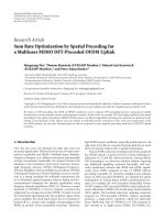
later. The block diagram of the system setup is shown in
Figure 1. The transmitted data streams d
u,1
, , d
u,N
of UE
u are transformed to the frequency domain via an N point
DFT and the DFT output x
u,1
, , x
u,N
is linear precoded
by v
u,1
, , v
u,N
, respectively. We assume equal power of the
transmitted signal, that is, E
{d
u,n
d
∗
u,n
}=P
total,u
/N,where
P
total,u
denotes the power constraint of UE u.NotethatDFT
precoding is unitary precoding which preserves the signal
energy and it will not change the power distribution of the
incoming signal, hence
E
x
u,n
x
∗
u,n
=
P
total,u
N
.
(1)
The N
×2 outputs of the linear precoder represent two spatial
data streams, each of which is processed at one antenna by
a Q point IDFT and cyclic prefix is inserted (CP-OFDM).
We assume that the assignment of each data stream uses
localized subcarrier allocationasappliedinLTEforbothUEs
and they share the same frequency resources. In principle,
other allocation methods including IFDMA and B-IFDMA
can also be applied. The resulting signal is subsequently
parallel to serial converted for transmission. The transmitted
signals of both UEs undergo multiple path propagation and
are received by the receiver at the BS. The receiver converts
the incoming data streams from serial to parallel, removes
the cyclic prefix, and processes them using a Q point DFT.
Next, the corresponding subcarrier demapping method and
ZF-MIMO equalization (EQ) is performed. Subsequently,
the equalized signal
x
u,1
, , x
u,N
is converted back to the
time domain via an N point IDFT for detection. In Figure 1,
the block diagram without DFT precoding at the transmitter
and IDFT at the receiver is referred to as the inner MIMO
OFDMA system.
Our system model only considers single-stream trans-
mission on each subcarrier for each UE. In principle, it is
possible for a UE to transmit multiple data streams by apply-
ing spatial multiplexing (SM) as discussed in [15] either with
or without spatial precoding. However, on one hand, SM
for a UE with spatial precoding will generally increase PAPR
with respect to single-antenna transmission [15]. On the
other hand, the performance of SM for a UE without spatial
precoding will be degraded by spatial correlation between
the antennas, which is mainly due to the limited antenna
separation in the UE. Therefore, it is better to multiplex
different data streams from different UEs than from different
antennas of the same UE, since the compound virtual MIMO
channel benefits from appropriate user grouping and may
achieve good rank, even if the two antennas of each UE
have high correlation. Moreover, the SC-FDMA transmission
structure for each antenna can be preserved in our model
hence maintains low PAPR if a common, say frequency-
independent spatial precoder is used for all the subcarriers
at a UE. This is especially critical for the cell edge users
to be able to bridge the long distance. Furthermore, single-
stream transmission is preferred in terms of implementation
complexity since coding and transmission can be simply
done as in the single-antenna system [16] and hence multiple
EURASIP Journal on Advances in Signal Processing 3
d
1,1
d
1,N
.
.
.
N point
DFT
precoding
x
1,1
x
1,N
.
.
.
.
.
.
.
.
.
.
.
.
Spatial
precoder
Spatial
precoder
Spatial
precoder
Q
point
IDFT
Add
cyclic
prefix
PS
converter
V
1,N
V
1,1
UE 1
(weak user)
V
1,1
= V
1,2
=···=V
1,N
Q
point
IDFT
Add
cyclic
prefix
PS
converter
.
.
.
.
.
.
.
.
.
d
2,1
d
2,N
.
.
.
N point
DFT
precoding
x
2,1
x
2,N
.
.
.
.
.
.
.
.
.
.
.
.
Spatial
precoder
Spatial
precoder
Spatial
precoder
Q
point
IDFT
Add
cyclic
prefix
PS
converter
V
2,N
V
2,1
UE 2
(strong user)
V
2,1
= V
2,2
=···= V
2,N
Q
point
IDFT
Add
cyclic
prefix
PS
converter
.
.
.
.
.
.
.
.
.
For
UE 1
BS
For
UE 2
.
.
.
N
point
IDFT
x
1,1
x
1,N
.
.
.
.
.
.
.
.
.
.
.
.
EQ
EQ
EQ
Q
point
DFT
Rem.
cyclic
prefix
PS
converter
.
.
.
N
point
IDFT
x
2,1
x
2,N
.
.
.
.
.
.
.
.
.
.
.
.
Q
point
DFT
Rem.
cyclic
prefix
PS
converter
DFT precoding
Inner OFDMA system
Inner OFDMA system
MIMO
channel
Figure 1: Block diagram of the SC-FDMA MIMO system with two UEs under consideration.
antennas can be easily integrated into the conventional
single-antenna system.
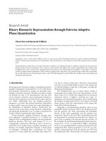
On each allocated subcarrier, the relationship between
the N point DFT output at the transmitter and the N point
IDFT input at the receiver can be illustrated as in Figure 2.
Let G
u,n
denote the channel matrix between the transmiting
antennas of the UE u on subcarrier n and the receiving
antennas at the BS (Note that the subcarrier index is counted
only in the set of allocated subcarriers). The compound
channel of UE u seen by the BS can be obtained by
4 EURASIP Journal on Advances in Signal Processing
N point DFT
output of UE 1
x
1,n
N point DFT
output of UE 2
x
2,n
Spatial
precoder
Spatial
precoder
MIMO
equalizer
N point
IDFT intput
v
1,n
v
2,n
G
1,n
G
2,n
BS
x
1,n
x
2,n
H
n
Figure 2: Spatial precoder for MIMO uplink with multiple transmit antennas at each UE and multiple antennas at the BS. The index n
represents the nth allocated subcarrier in the system.
h
u,n
= G
u,n
v
u,n
. The multiuser MIMO channel matrix on
subcarrier n is written as
H
n
=
h
1,n
h
2,n
=
G
1,n
v
1,n
G
2,n
v
2,n
.
(2)
Signals transmitted on subcarrier n from all the UEs are
collected in a vector and denoted by x
n
= [x
1,n
x
2,n
]
T
.
The received signal on subcarrier n at the BS is then given
by y
n
= H
n
x
n
+ n
n
,wheren
n
is the white Gaussian noise
with variance E
{n
n
n
H
n
}=σ
2
I. After the linear ZF-MIMO
equalization, the postdetection SNR of UE u on subcarrier n
in the inner OFDMA system, γ
u,n
, can be calculated as
γ
u,n
=
E
x
u,n
2
σ
2
H
H
n
H
n
−1
u,u
,
(3)
where the operator [
·]
u,u
denotes the uth diagonal element
of the matrix [
·]. The postdetection SNR for the nth compo-
nent at the IDFT outputs for UE u is related with γ
u,n
by [17]
γ
u,n
=
N
N
n
=1
1/γ
u,n
,
(4)
which is the harmonic mean of γ
u,n
and it is the same for
all the components. Note that (4) holds regardless of the
used subcarrier allocation method. Using Shannon’s formula
theachievablespectralefficiency of the sub-channel between
each input and output in SC-FDMA system for UE u is then
given by log
2
(1 + γ
u,n
) and the system sum rate of the MIMO
SC-FDMA system is the rate sum of all the subcarriers of all
the UEs [17], that is,
R
=
2
u=1
N
n=1
log
2
1+γ
u,n
=
2
u=1
N
n=1
log
2
1+
N
N
n
=1
1/γ
u,n
.
(5)
According to (1), (2), (3), and (5), our objective to maximize
the system sum rate R can be formulated as follows:
max
v
1,1
, ,v
2,N
2
u=1
N log
2
⎛
⎜
⎝
1+
P
total,u
σ
2
N
n
=1
H
H
n
H
n
−1
u,u
⎞
⎟
⎠
s.t.
v
u,n
2
2
= 1, u = 1, 2; n = 1, , N,
(6)
where optimization is performed over all possible precoding
vectors subject to the constraints that the precoder is
normalized according to the transmit power constraint. Note
that our system model also includes the special case that only
one antenna is available at each UE (conventional virtual
MIMO), by setting v
u,n
to [1 0]
T
or [0 1]
T
for u = 1, 2; n =
1, , N depending on which antenna is used by the UEs.
3. Spatial Precoder Optimization
A direct optimization of the objective function in (6)
seems to be very difficult and therefore we look for an
approximative solution. According to (5), a higher γ
u,n
for
both UEs on subcarrier n in the inner OFDMA system leads
to a higher R; therefore, to maximize R, it is beneficial to
maximize γ
u,n
, or equivalently the data rate for both UEs in
the inner OFDMA system and at the same time taking the
objective function (harmonic mean of γ
u,n
’s) into account.
3.1. Eigenbeamforming. If only a single UE, for example, UE
u is present and other UEs do not transmit in the system
according to Figure 2, the optimum spatial precoder on
subcarrier n at the transmitter and equalizer at the receiver
is given by the dominant right and left singular vector of G
u,n
or equivalently the dominant eigenvector (DEV) of G
H
u,n
G
u,n
and the dominant eigenvector of G
u,n
G
H
u,n
, respectively. This
transmission strategy is called dominant eigenbeamforming
transmission (DET). Under this condition, the postdetection
SNR on subcarrier n before IDFT is maximized and this
relation can be expressed as
x
u,n
=
λ
u,1
x
u,n
+ z
u,n
,
(7)
where λ
u,1
is the dominant (largest) eigenvalue of G
H
u,n
G
u,n
for
UE u and z
u,n
is the AWGN noise with variance σ
2
u,n
for UE u
EURASIP Journal on Advances in Signal Processing 5
on subcarrier n. Hence the postdetection SNR on subcarrier
n can be calculated as
γ
DEV
u,n
=
P
total,u
σ
2
u,n
N
λ
u,1
.
(8)
InthecasethatbothUEsarepresent,ifbothUEsuseDET
strategy for transmission, maximum power of both UEs is
coupled into the channel but the UEs’ signal will generally
interfere with each other unless their effective channels
happen to be orthogonal to each other, that is, h
H
1,n
h
2,n
= 0.
For this special case, a ZF-MIMO equalizer reduces to
a matched filter which maximizes the output SNR of both
data streams [18] and thus also maximizes the achievable
system sum rate of both UEs on subcarrier n.
3.2. Orthogonal Precoder (OP). On the other hand, the
transmitted signal from both UEs can always be made
interference free to each other if one UE, that is, UE 2,
applies a precoding vector in a way such that its effective
channel h
2,n
is orthogonal to that of the reference UE, that
is, UE 1. In other words, the signal of the reference UE
will not be disturbed and the system sum rate will increase
due to the accommodation of the data stream from the
additional UE. For convenience, this precoder is referred to
as an orthogonal precoder in the sequel. Denote the effective
channel of the reference UE u on subcarrier n as h
u,n
,the
orthogonal precoder v
u
,n
for the UE u
with respect to the
reference UE should fulfill
h
H
u,n
G
u
,n
v
u
,n
=
0,
(9)
where G
u
,n
is the physical channel of the UE to which an
orthogonal precoder should be applied. The solution to (9)
can be obtained as
v
⊥
u
,n
=
G
−1
u
,n
h
⊥
u,n
G
−1
u
,n
h
⊥
u,n
2
,
(10)
where h
⊥
u,n
represents the vector orthogonal to h
u,n
and the
denominator is used to normalize the power of the precoder.
However, due to the limited degrees of freedom of
thelinearprecoder,afterprecodingtheeffective channel
orthogonal to the reference UE may experience bad channel
condition and therefore the UE which has to transmit the
signal in this direction will suffer from low data rate.
In this work, our proposal is to find an appropriate
trade-off between completely eliminating the interference
(irrespective of how much energy is lost for UE 2) and
preserving as much energy as possible for both UEs (at the
expense of possibly suffering from interference between the
data streams).
3.3. Combination of DEV Precoder and Orthogonal Precoder.
The fact that the DEV precoder preserves as much energy as
possible for both UEs (at the expense of possibly suffering
from high interference between the data streams) and the
orthogonal precoder completely eliminates the interference
(irrespective of how much energy is lost for one of the UEs)
suggests that we can find an appropriate trade-off between
them. To this end, we propose for each UE a precoder
which is the linear combination of its DEV precoder and
the orthogonal precoder (with which the resulting beam is
orthogonal to the dominant eigenbeam of the other UE), that
is,
v
DEV,⊥
u,n
=
α
u,n
v
DEV
u,n
+
1 −α
u,n
v
⊥
u,n
α
u,n
v
DEV
u,n
+
1 −α
u,n
v
⊥
u,n
2
,
(11)
where the coefficients α
u,n
and (1 − α
u,n
), α
u,n
∈ [0,1],
define for UE u the weighting for the DEV precoder and the
orthogonal precoder, respectively. The denominator of (11)
is used to normalize the power of the precoder. Note that for
the special case of α
u,n
= 0andα
u,n
= 1, the precoder of
UE u corresponds to its orthogonal precoder and its DEV
precoder, respectively. In order to optimize the system sum
rate, the α
u,n
’s should be optimized jointly over all subcarriers
for all UEs.
3.4. Selection Procedure. Using (11)asthespatialprecoder
for each UE, the problem of maximizing the system sum rate
in the ZF-equalized MIMO SC-FDMA system with two UEs
canbereformulatedasfindinganoptimumα
u,n
for the linear
combination of its DEV and its orthogonal precoder such
that the system sum rate is maximized. Consequently, (6)can
be rewritten as
max
2
u=1
N log
2
⎛
⎜
⎝
1+
P
total,u
σ
2
N
n
=1
H
H
n
(
α
n
)
H
n
(
α
n
)
−1
u,u
⎞
⎟
⎠
s.t. 0 ≤ α
1,n
≤ 1, 0 ≤ α
2,n
≤ 1, n = 1, , N,
(12)
where
α
n
=
α
1,n
, α
2,n
H
n
=
⎡
⎢
⎣
G
1,n
α
1,n
v
DEV
1,n
+
1 −α
1,n
v
⊥
1,n
T
G
2,n
α
2,n
v
DEV
2,n
+
1 −α
2,n
v
⊥
2,n
T
⎤
⎥
⎦
T
(13)
is the compound channel matrix on subcarrier n in the
system. In the above optimization problem, the weighting
factors α
u,n
have to be optimized jointly among all users
and all subcarriers. There are mainly two issues associated
with it. The first issue is related to the PAPR of the transmit
waveform. Due to the frequency selectivity of the channels,
the optimal precoding vector will vary from subcarrier to
subcarrier in general. Such frequency-dependent precoding
vectors, if applied, will destroy the single carrier structure
of the transmitted signal. Note that applying precoding
vectors after DFT in the frequency domain is equivalent to a
convolution and summation of the data symbols in the time
domain [15], thus PAPR of the composite transmitted signal
will increase with respect to single antenna transmission. The
other issue is related with computational complexity, which
increases exponentially in the number of subcarriers N and
6 EURASIP Journal on Advances in Signal Processing
in the number of UEs U. We will address these two issues
separately in the following.
To address the PAPR issue, we propose to use a fre-
quency-independent spatial precoder for one UE, preferably
the weaker UE. As a result, the single carrier structure of
the transmit signal and hence the low PAPR property at
each antenna for this UE can be maintained. In this work,
we use the dominant eigenvector of the average correlation
matrix (1/N)
N
n
=1
(G
H
n
G
n
) as the precoding vector, where
the subscription u is dropped here for notational simplicity.
In addition, since the same precoder is applied for all
subcarriers, the signal processing complexity is reduced
and the signalling overhead to inform the UE about the
precoder is also reduced considerably. Subsequently, the best
coefficient of α is found numerically for the other UE such
that the system sum rate is maximized and its resulting pre-
coding vector is referred to as the optimum complementary
precoder (OCP) in our context.
In order to reduce the computational complexity of the
selection procedure, optimization of (12)canbeperformed
on an arbitrary subcarrier first to obtain the best precoder
forthatsubcarrierandthenitisconsideredfixedforthe
optimization of the next subcarrier. As a result, the compu-
tational complexity is linear in the number of subcarriers.
A description of the algorithm with two UEs can be found in
Algorithm 1.
Algorithm 1 aims to maximize the rate sum of all UEs.
It can also be extended to incorporate different weighting for
the rate of different UEs so as to maximize the weighted sum
rate of all UEs. By introduction of the weighting factor w
u
for the rate R
u
of the uth UE, the two user weighted sum
rate problem is R
total
=
2
u
=1
w
u
R
u
and the optimal α
2,n,opt
in
Algorithm 1 should be modified as
α
2,n,opt
=argmax
2
u=1
w
u
N ·log
2
⎛
⎜
⎝
1+
P
total,u
/σ
2
k
u
+
H
H
n
α
2,n
H
n
α
2,n
−1
u,u
⎞
⎟
⎠
.
(14)
This modified version of Algorithm 1 dealing with the
weighted sum rate problem is related to the achievable rate
region in the system, which will be interesting for resource
allocation and QoS optimization. Changing the weights, any
point on the boundary of the achievable rate region can be
achieved.
3.5. Scheduling. In Algorithm 1, one UE, for example, UE 1,
always utilizes its dominant eigenbeam direction and then
UE 2 has to transmit in a direction such that the system
sum rate is maximized. The resulting transmission direction
of UE 2 generally differs from its own dominant eigenbeam
direction. It can be expected that in the case of both UEs
having similar channel conditions, on average the postdetec-
tion SNRs of UE 1 in the inner OFDMA system are higher
than those of UE 2. According to (4), higher postdetection
SNRs lead to a higher harmonic mean, corresponding to
the postdetection SNRs of the SC-FDMA system. Therefore,
Input: Channel realization G
1,1
, , G
2,N
and
power constraint P
total,u
for 1 ≤ u ≤ 2
Initialization: Calculate the dominant eigenvector
v
DEV
1
of the average correlation matrix
(1/N)
N
n
=1
(G
H
1,n
G
1,n
). For 1 ≤ n ≤ N,
perform SVD for G
2,n
,obtainv
DEV
2,n
,set
h
1,n
= G
1,n
v
DEV
1
,calculatev
⊥
2,n
,
construct v
DEV,⊥
2,n
according to (11), set
h
2,n
= G
2,n
v
DEV,⊥
2,n
and k
u
= 0
for n
= 1:N do
calculate H
n
according to (2);
α
2,n,opt
=
argmax
2
u
=1
N log
2
1+
P
total,u
/σ
2
k
u
+[(H
H
n
(α
2,n
)H
n
(α
2,n
))
−1
]
u,u
;
H
n,opt
=
[h
1,n
G
2,n
[α
2,n,opt
v
DEV
2,n
+(1−α
2,n,opt
)v
⊥
2,n
]];
k
u
= k
u
+[(H
H
n,opt
H
n,opt
)
−1
]
u,u
, u = 1, 2;
end
output: v
DEV
1
, α
2,n,opt
and v
DEV,⊥
2,n
according to
(11), for 1
≤ n ≤ N
Algorithm 1: Spatial precoder optimization algorithm.
it follows that on average the rate of UE 1 is higher than
that of UE 2 in the MU-MIMO SC-FDMA system. From the
UEs’ perspective, this fixed optimization order is biased and
it may cause the individual rate of the UEs to differ a lot from
each other. Another factor which may affect the individual
rate of the UEs is that the UE which uses OCP may produce
strong interference to the UE which uses the DEV precoder.
This will not cause any problem if both UEs have similar
channel conditions. However, if their channel qualities are
largely unbalanced (e.g., 10 dB difference), even the weaker
UE always transmits in its dominant eigenbeam direction, a
small amount of interference from the much stronger UE will
have a strong impact on the rate of the weaker UE. In this
situation, it is desirable to let the stronger UE transmit in
the direction orthogonal to that of the weaker UE. This leads
to our following simple scheduling algorithm to mitigate the
aforementioned problems and to balance the individual rate
of the UEs.
The scheduler works as follows. It keeps track of the
average rate R
avg,u
of each UE, which will be updated on
per subframe basis. In subframe t, the scheduling algorithm
assigns the DEV precoder to UE u
∗
with smaller R
avg,u
in the system, which aims to give higher priority to the
weaker UE to balance the individual user rate. In addition,
in order to avoid interfering the rate of weaker UE if the
UEs experience largely unbalanced channel conditions in
the system, a weighting factor β is introduced to weight the
channel orthogonal to that of the weaker UE by setting
h
u,n
=
⎧
⎪
⎪
⎨
⎪
⎪
⎩
βG
u,n
v
⊥
u,n
v
⊥
u,n
2
, α = 0, β ≥ 1,
G
u,n
v
DEV,⊥
u,n
, α
/
=0
(15)
EURASIP Journal on Advances in Signal Processing 7
in the precoder optimization algorithm, where
u denotes
the UE with higher average rate R
avg,u
.In(15), choosing a
larger β means to virtually boost the quality of the channel
orthogonal to the transmission direction of the weaker UE,
so that it is treated as a good channel and the selection
procedure preferably picks it up for the stronger UE. In
other words, a bigger β indicates higher importance that the
UE with higher average rate in the past should transmit in
a direction which does not cause any interference to the UE
with lower average rate in the past and vice versa.
4. Simulation Results
To evaluate the performance of the proposed spatial pre-
coders in a 2
× 2 uplink MIMO system with two UEs as
shown in Figure 2, simulations are conducted in the 3GPP
LTE uplink with the parameter assumptions given in Ta b l e 1 .
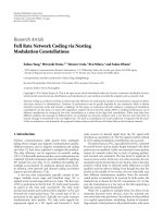
A snapshot of the subcarrier channel power gain between
the UEs and the BS is illustrated in Figure 3. For simplicity, it
is further assumed that each resource block (RB) experiences
the same channel condition and its channel frequency
response is represented by the middle, that is, the 6th, subcar-
rier of the RB. Under this condition, performance evaluation
can be conducted per RB basis and the concept meant for a
subcarrier in our previous discussion can be directly applied
to an RB to reduce the computational complexity. In the
following, first the performance is evaluated using a channel
snapshot for illustrative purpose. Then we present results in
terms of average spectral efficiency for different bandwidth
and SNR conditions.
The upper part of Figure 4 shows the postdetection SNR
γ
u,n
of the inner OFDMA system using a channel snapshot of
20 MHz (totally 100 RBs) as depicted in Figure 3.Notethat
only 20 RBs (240 subcarriers) are shown for better visibility
of the details. The dashed lines represent the results for the
conventional UEs with each having only a single antenna,
that is, setting v
u,n
= [1 0] for all u’s and n’s in our model.
The solid lines stand for the results obtained by the proposed
precoding scheme where UE 1 employs the dominant EV of
the average channel correlation matrix as precoders for all
the subcarriers and UE 2 uses the OCP for each subcarrier.
The spectral efficiency of each sub-channel between each
input and output component in the SC-FDMA system is
plotted in the lower part of Figure 4. It can be observed that
the proposed algorithm significantly improves the spectral
efficiency, or in other words the rate of the UEs in the system.
Next, the statistics of the postdetection SNR is studied for
the conventional virtual MIMO SC-FDMA and the proposed
MIMO SC-FDMA with spatial precoding, where a setting
of two UEs with the same average SNR
= 10 dB over 15
RBs (
≈3 MHz) is assumed. Statistics are collected from 50
randomly distributed locations in a cell and 100 subframes
are considered assuming that each UE randomly moves from
each location. The complementary cumulative distribution
function (CCDF) of the postdetection SNR for both schemes
is compared in Figure 5, which shows the probability that
the postdetection SNR is larger than a certain value. It can
be seen that with the proposed spatial precoding scheme the
postdetection SNRs of both UEs are significantly increased,
Table 1: Parameter assumptions for simulation.
Parameters Assumption
Carrier frequency 2 GHz
Transmission bandwidth 3 MHz, 20MHz
Subframe duration 1 ms
Subcarrier spacing 15 KHz
Number of subcarriers 180, 1200
Number of subcarriers per RB 12
Channel model 3GPP SCME urban macro [19]
Number of UEs 2
Number of BSs 1
Antennas per UE 2
Antennas per BS 2
UE antenna spacing 0.5 wavelength
BS antenna spacing 10 wavelengths
UE velocity 10 m/s
where the improvement for the UE using dominant EV
precoding is much larger than that for the UE using OCP.
For the same setting, Figure 6 shows the cumulative
distribution function (CDF) of the system spectral efficiency
and the individual user spectral efficiency for the conven-
tional virtual MIMO SC-FDMA and the proposed MIMO
SC-FDMA with spatial precoding. Spectral efficiency for UE
1 and UE 2 is indicated by dashed and dashdot curves,
respectively. The system spectral efficiency is indicated by
the solid curve. It can be observed that in comparison
with the conventional virtual MIMO SC-FDMA the 50
percentile achievable system spectral efficiency almost dou-
bles after applying the proposed scheme for different fixed
optimization orders. It can also be clearly seen that with the
fixed optimization orders, the UE using the dominant EV
precoder always has higher average spectral efficiency than
the one using OCP. If the proposed spatial scheduler is used,
individual spectral efficiency of the UEs are balanced and
theCDFoftheachievablesystemspectralefficiency (green)
lies almost on top of those obtained by fixed optimization
orders (red and blue). For reference, the case that both UEs
use frequency-dependent precoding according to (11)isalso
shown for both the SC-FDMA system and the OFDMA
system. Note that although higher spectral efficiency is
possible in this case, the single-carrier structure and hence
the low PAPR property cannot be maintained for both UEs
any more.
Figure 7 depicts the performance comparison assuming
100 RBs are available in the system and other parameters
remain the same as in the previous simulation. It can be seen
that both the conventional virtual MIMO SC-FDMA and
the proposed precoding schemes have inferior performance
to the case with 15 RBs (cf. Figure 6). The reason is as
follows. In the system with relatively small bandwidth,
diversity offered in the frequency domain is limited hence all
subcarriers within the system bandwidth experience similar
channel conditions, that is, in some subframes channels are
good and in others they are bad. As the transmission
bandwidth increases, diversity offered in the bandwidth
8 EURASIP Journal on Advances in Signal Processing
200150100500
Subcarrier index
−30
−20
−10
0
10
Channel power gain (dB)
UE1, |g
11
|
2
UE1, |g
21
|
2
UE1, |g
12
|
2
UE1, |g
22
|
2
(a)
200150100500
Subcarrier index
−40
−30
−20
−10
0
10
Channel power gain (dB)
UE2, |g
11
|
2
UE2, |g
21
|
2
UE2, |g
12
|
2
UE2, |g
22
|
2
(b)
Figure 3: Channel power gain snapshot between the UEs and the BS according to Figure 2; g
ij
denotes the subcarrier frequency response
between the jth transmitter of the UE and the ith receiver at the BS.
20181614121086420
Index of RB
−10
−5
0
5
10
15
20
SNR (dB)
Conventional, UE1
Conventional, UE2
Proposed, UE1, EV
Proposed, UE2, OCP
Postdetection SNR of the inner OFDMA system
(a)
20181614121086420
Symbol index after IDFT
0
2
4
6
8
Spectral efficiency
(bits/s/Hz)
Conventional, UE1
Conventional, UE2
Conventional,
UE1 and UE2
Proposed, UE1, EV
Proposed, UE2, OCP
Proposed,
UE1 and UE2
Achievable spectral efficiency in the SC-FDMA system
(b)
Figure 4: Performance comparison between the conventional virtual MIMO SC-FDMA and the proposed MIMO SC-FDMA with precoding
using the channel snapshot in Figure 3. (Upper: postdetection SNR of the inner OFDMA system; Lower: achievable spectral efficiency in the
SC-FDMA system.)
is higher. As a result, all subframes consist of a similar
number of strong/weak subcarriers and a similar number of
subcarriers in which both UEs have similar spatial signatures.
It follows that the number of low postdetection SNRs in
the inner OFDMA system is similar in all subframes. Since
the postdetection SNRs of all components in the SC-FDMA
system are the harmony mean of the postdetection SNRs
of the inner OFDMA system and they are mainly restricted
by small values, it turns out that having similar number of
low postdetection SNRs for each subframe is less spectrally
efficient than having more low postdetection SNRs for some
subframes and less for the others [20]. Nevertheless, the
proposed scheme still achieves about twice as high system
spectral efficiency as the conventional scheme.
Figure 8 compares the performance with unequal average
received SNR for different UEs, that is, SNR
UE1
= 0dBand
SNR
UE2
= 10 dB in the 3 MHz bandwidth. About twice the
system spectral efficiency with respect to the conventional
scheme can be expected from the proposed spatial precoding
schemes for different fixed optimization orders. It can be
seen that the scheme which always gives higher priority to
the weaker UE, that is, DEV and OCP are applied to the
weaker UE and the stronger UE, respectively, still results in
significant lower rate for weaker UE (red dashed) than for the
stronger UE (red dashdot). This is due to the strong amount
of interference caused by the stronger UE. Nevertheless, by
applying our prosed scheduling algorithm (green) with β
=
10, comparable individual rate of the UEs can be achieved.
Figures 9 and 10 illustrate the achievable average rate
(bits/s/Hz) obtained by using the modified version of
Algorithm 1 (which incorporates weighted sum rate maxi-
mization, cf. (14)) in a two-UE SCME urban macro scenario
according to Ta b l e 1 for different SNR conditions. Only the
case with 3 MHz system bandwidth is considered and the
rate results are evaluated over 2000 subframes. The boundary
point is computed with the modified Algorithm 1 for 33
different weights with w
1
ranging from 0.01 to 1.99 in steps of
0.06 (w
2
= 2−w
1
). The red curve is obtained by choosing the
DEV of the average channel correlation matrix as the spatial
precoder for UE 1 and choosing OCP for each subcarrier
EURASIP Journal on Advances in Signal Processing 9
2520151050−5−10−15−20−25
Postdetection SNR (dB)
0
0.1
0.2
0.3
0.4
0.5
0.6
0.7
0.8
0.9
1
CCDF of postdetection SNR
Conventional, UE1
Conventional, UE2
Proposed, UE1, DEV
Proposed, UE2, OCP
Postdetection SNR in SC-FDMA, 15 RBs,
SINR
UE1
= SNR
UE2
= 10 dB
UE2
UE1
Figure 5: Complementary cumulative distribution function
(CCDF) of the postdetection SNR between the conventional
MIMO SC-FDMA and the proposed MIMO SC-FDMA with spatial
precoding. 15 RBs are available in the system and both UEs have the
same average received SNR of 10 dB.
for UE 2 (by optimizing the linear combination of DEV and
orthogonal precoder) such that the weighted sum rate of two
UEs is maximized. The blue curve is obtained by the opposite
optimization order, that is, choosing DEV for UE 2 and OCP
for UE 1. If the UEs have the ability to coordinate the timing,
theratepairsontheblackdashed curve (but not on the blue
and red curves) can be achieved by time-sharing.
The UE rate pairs at the two ends of the black dashed
curve correspond to the case where strongly different weight-
ing factors are applied to different UEs (w
= 0.01 for one UE
and w
= 1.99 for the other). They also correspond to case
where the UE with higher weighting using DEV precoder and
the UE with lower weighting using the orthogonal precoder
(OP). Imposing higher weighting to the UE means giving
higher priority to the UE to maximize its own data rate,
then the UE with lower weighting has to transmit in the
direction without causing strong interference to the UE with
higher weighting. The extreme case is that the UE with lower
weighting chooses the OP such that it does not cause any
interference to the UE with higher weighting.
For comparison, three additional transmit-precoding
strategies are also considered and their achievable rate
performances are shown in the figures. Each strategy applies
a frequency-independent precoder on all subcarriers and the
precoder can be different for different subframes. The first
strategy is that each UE uses its own DEV of the average
channel correlation matrix as the spatial precoder. In other
words, each UE roughly couples maximum power into the
channel without taking care of how much interference will
be caused to each other. The second strategy is that each
UE adaptively selects one precoder from the 4 predefined
14121086420
Averageachievablespectralefficiency (bits/s/Hz)
0
0.1
0.2
0.3
0.4
0.5
0.6
0.7
0.8
0.9
1
CDF of average achievable spectral efficiency
Conventional, UE1
Conventional, UE2
Conventional, UE1 and UE2
Proposed, UE1, DEV
Proposed, UE2, OCP
Proposed, UE1 DEV and UE2 OCP
Proposed, UE1, OCP
Proposed, UE2, DEV
Proposed, UE1 OCP and UE2 DEV
Proposed scheduler, UE1
Proposed scheduler, UE2
Proposed scheduler, UE1 and UE2
SC-FDMA, UE1, (11)
SC-FDMA, UE2, (11)
SC-FDMA, UE1 (11) and UE2 (11)
OFDMA, UE1 (11) and UE2 (11)
SC-FDMA, 15 RBs, SNR
UE1
= 10dB, SNR
UE2
= 10dB
Figure 6: Cumulative distribution function (CDF) of the achiev-
able spectral efficiency by using conventional virtual MIMO with
a single antenna per UE (black) and by using a spatial precoder
according to Figure 2 with fixed optimization order (red and blue)
and a spatial scheduler (green) for an SC-FDMA system (β
= 1).
For reference, the case that both UEs use frequency-dependent
precoding according to (11)isincludedfortheSC-FDMAsystem
(cyan) and for the OFDMA system (magenta). 15 RBs are available
in the system and both UEs have the same average received SNR of
10 dB.
precoding vectors (They are the v
1
= (1/
√
2)[1 1]
T
, v
2
=
(1/
√
2)[1 −1]
T
, v
3
= (1/
√
2)[1 j]
T
,andv
4
= (1/
√
2)[1 −
j]
T
, resp.) specified in LTE systems [21](referredtoas
the LTE DFT codebook) such that the system sum rate is
maximized (16 combinations). The last strategy is that each
UE adaptively selects one antenna for transmission (totally 4
possibilities) such that the system sum rate is maximized. It
can be observed that all these transmit precoding strategies
have inferior rate performance to the proposed scheme.
Especially at low and moderate SNR conditions, the gain
achieved by the proposed scheme is shown up to 40% over
the adaptive LTE DFT codebook strategy and up to 70% over
the other considered strategies.
For unequal SNR conditions of the UEs, the rate achieved
by all the transmit precoding schemes exhibits bias toward
the stronger UE. Obviously as shown in Figure 10,the
proposed precoding scheme outperforms other considered
schemes.
10 EURASIP Journal on Advances in Signal Processing
14121086420
Averageachievablespectralefficiency (bits/s/Hz)
0
0.1
0.2
0.3
0.4
0.5
0.6
0.7
0.8
0.9
1
CDF of average achievable spectral efficiency
Conventional, UE1
Conventional, UE2
Conventional, UE1 and UE2
Proposed, UE1, DEV
Proposed, UE2, OCP
Proposed, UE1 DEV and UE2 OCP
Proposed, UE1, OCP
Proposed, UE2, DEV
Proposed, UE1 OCP and UE2 DEV
Proposed scheduler, UE1
Proposed scheduler, UE2
Proposed scheduler, UE1 and UE2
SC-FDMA, UE1, (11)
SC-FDMA, UE2, (11)
SC-FDMA, UE1 (11) and UE2 (11)
OFDMA, UE1 (11) and UE2 (11)
SC-FDMA, 100 RBs, SNR
UE1
= 10dB, SNR
UE2
= 10dB
Figure 7: Parameter setting is the same with Figure 6 but 100 RBs
are available in the system.
5. Conclusions
We propose to apply DFT precoding combined with spatial
precoding to optimize the system sum rate in a MIMO SC-
FDMA uplink. Depending on the requirements, at least one
of the UEs can optionally apply a frequency nonselective pre-
coding to obtain a single-carrier waveform with low PAPR.
The required feedback overhead to convey the precoder
decision to the UE is significantly reduced. Furthermore, to
handle the fairness issues between the UEs, a simple spatial
scheduler has been proposed within the framework to effec-
tively steer and balance the individual user rate exemplarily.
Simulation results show that the system spectral efficiency
almost doubles for various SNR conditions compared to
the case where each UE has only one transmit antenna.
Finally, weighted sum rate maximization is also incorporated
in the algorithm and its achievable rate region is presented
and potential gains are shown compared to other popular
precoding schemes for LTE uplink scenarios.
6. Open Problems and Future Work
For the scenario with more than two UEs and more than two
antennas in the system, the principle of Algorithm 1 can be
extended by constructing candidate precoders v
DEV,⊥
u,n
for UE
109876543210
Average achievable spectral efficiency (bits/s/Hz)
0
0.1
0.2
0.3
0.4
0.5
0.6
0.7
0.8
0.9
1
CDF of average achievable spectral efficiency
Conventional, UE1
Conventional, UE2
Conventional, UE1 and UE2
Proposed, UE1, DEV
Proposed, UE2, OCP
Proposed, UE1 DEV and UE2 OCP
Proposed, UE1, OCP
Proposed, UE2, DEV
Proposed, UE1 OCP and UE2 DEV
Proposed scheduler, UE1
Proposed scheduler, UE2
Proposed scheduler, UE1 and UE2
SC-FDMA, UE1, (11)
SC-FDMA, UE2, (11)
SC-FDMA, UE1 (11) and UE2 (11)
OFDMA, UE1 (11) and UE2 (11)
SC-FDMA, 15 RBs, SNR
UE1
= 10 dB, SNR
UE2
= 10dB
Figure 8: Parameter setting is the same with Figure 6 but with
unequal average received SNR for the UEs: SNR
UE1
= 0dB and
SNR
UE2
= 10 dB; β = 10.
u (2 ≤ u ≤ U) according to (11), where v
DEV
u,n
can be cal-
culated by performing singular value decomposition (SVD)
for the associated channel matrix and v
⊥
u,n
can be obtained
by using (10). However, it might happen that the solution
to (10) does not exist. Therefore, advanced algorithm design
is needed. A partial solution to accommodate multiple UEs
is to divide the whole available system bandwidth into
small partitions and apply the proposed algorithm for each
partition with two UEs.
In the proposed scheduling algorithm, the introduction
of a weighting factor β isshowntobeabletobalancethe
individual user rates to some extent. A typical value of β
is between 1 and 10 depending on the channel quality of
different users. However, the optimization of β for different
channel conditions to achieve comparable rates for all users
is an open question and subject to future study.
The proposed algorithm assumes that perfect channel
state information is available at the BS which only provides
an upper bound for the system performance. In a practical
system, channel state information estimated in the BS will
not be perfect. Nevertheless, the proposed algorithm can be
beneficial to improve the system sum rate in LTE femtocell
(home BS) [22] scenarios, where UEs typically move at very
EURASIP Journal on Advances in Signal Processing 11
Increase weighting
for UE2
Increase weighting
for UE1
UE1 DEV and UE2 OP
SNR
1
= SNR
2
= −10dB
SNR
1
= SNR
2
= 0dB
SNR
1
= SNR
2
= 10 dB
UE1 OP and UE2 DEV
10
1
10
0
10
−1
Achievable average rate of UE1 (bits/s/Hz)
10
−1
10
0
10
1
Achievable average rate of UE2 (bits/s/Hz)
UE1 DEV and UE2 OCP
UE1 OCP and UE2 DEV
DEV/OCP rate region
UE1 DEV and UE2 DEV
LT E D F T c od eb o ok ( a d a p tive )
Antenna selection (adaptive)
SC-FDMA, 3 MHz bandwidth (15 RBs), n
T,1
= n
T,2
= n
R
= 2
Figure 9: Achievable average rate for two UEs for different transmit
precoding strategies in the SCME “urban macro” scenario accord-
ing to Ta b l e 1 . Both UEs share 3 MHz bandwidth to communicate
with the serving BS using the same time and frequency resources.
Both UEs have the same SNR.
low speed in a limited area. In such scenarios, channels of
all UEs are quasic-static, which makes it possible for the BS
to continuously improve channel estimation with the help of
the reference signals [21]sentfromtheUEs.
References
[1] J. T. E. McDonnell and T. A. Wilkinson, “Comparison of com-
putational complexity of adaptive equalization and OFDM
for indoor wireless networks,” in Proceedings of the 7th IEEE
International Symposium on Personal, Indoor and Mobile Radio
Communications (PIMRC ’96), pp. 1088–1090, October 1996.
[2] S. H. Han and J. H. Lee, “An overview of peak-to-average
power ratio reduction techniques for multicarrier transmis-
sion,” IEEE Wir eless C ommunications, vol. 12, no. 2, pp. 56–65,
2005.
[3]H.WuandT.Haustein,“Energyandspectrumefficient
transmission modes for the 3GPP-LTE uplink,” in Proceedings
of IEEE International Symposium on Personal, Indoor and
Mobile Radio Communications (PIMRC ’07), Athens, Greece,
September 2007.
[4] H. G. Myung, J. Lim, and D. J. Goodman, “Peak-to-average
power ratio of single carrier FDMA signals with pulse
shaping,” in Proceedings of the 17th IEEE International Sym-
posium on Personal, Indoor and Mobile Radio Communications
(PIMRC ’06), Helsinki, Finland, September 2006.
Increase weighting
for UE2
Increase weighting
for UE1
UE1 DEV and UE2 OP
UE1 OP and UE2 DEV
10
1
10
0
Achievable average rate of UE1 (bits/s/Hz)
10
1
10
0
Achievable average rate of UE2 (bits/s/Hz)
UE1 DEV and UE2 OCP
UE1 OCP and UE2 DEV
DEV/OCP rate region
UE1 DEV and UE2 DEV
LT E D F T c od eb o ok ( a d a p tive )
Antenna selection (adaptive)
SC-FDMA, 3 MHz bandwidth (15 RBs), n
T,1
= n
T,2
= n
R
= 2
Figure 10: Achievable average rate for two UEs for different
transmit precoding strategies in the SCME “urban macro” scenario
according to Ta b l e 1 . Both UEs share 3 MHz bandwidth to com-
municate with the serving BS using the same time and frequency
resources. Unequal SNR with 10 dB difference is assumed for the
UEs (SNR
UE1
= 0dB,SNR
UE2
= 10 dB).
[5] V. Jungnickel, T. Hindelang, T. Haustein, and W. Zirwas, “SC-
FDMA waveform design, performance, power dynamics and
evoluation to MIMO,” in Proceedings of IEEE International
Conference on Portable Information Devices,Orlando,Fla,USA,
March 2007.
[6]H.G.Myung,“IntroductiontosinglecarrierFDMA,”in
Proceedings of the 15th European Signal Processing Conference
(EUSIPCO ’07), Poznan, Poland, September 2007.
[7] 3GPP TSG RAN, “Some aspects of single-carrier transmission
for EUTRA,” R1-050765, August-September 2005.
[8] U. Sorger, I. De Broeck, and M. Schnell, “Interleaved FDMA—
a new spread-spectrum multiple-access scheme,” in Proceed-
ings of IEEE International Conference o n Communications
(ICC ’98), vol. 2, pp. 1013–1017, Atlanta, Ga, USA, June 1998.
[9]T.Svensson,T.Frank,D.Falconer,M.Sternad,E.Costa,and
A. Klein, “B-IFDMA-a power efficient multiple access scheme
for non-frequencyadaptive transmission,” in IST Mobile and
Wireless Communications Summit, Budapest, Hungary, July
2007.
[10] T. Frank, A. Klein, and T. Haustein, “A survey on the envelope
fluctuations of DFT precoded OFDMA signals,” in Proceed-
ings of IEEE International Conference o n Communications
(ICC ’08), pp. 3495–3500, Beijing, China, May 2008.
[11] WINNER, “Final report on identified RI key technologies,
system concept, and their assessment,” Tech. Rep. D2.10 v. 1.0,
WINNER-2003- 507581, December 2005.
12 EURASIP Journal on Advances in Signal Processing
[12]W.Yu,W.Rhee,S.Boyd,andJ.M.Cioffi, “Iterative water-
filling for Gaussian vector multiple-access channels,” IEEE
Transactions on Information Theory, vol. 50, no. 1, pp. 145–
152, 2004.
[13] M. Sternad, T. Svensson, and G. Klang, “The WINNER B3G
system MAC concept,” in Proceedings of the 64th IEEEVehicular
Technology Conference (VTC ’06), pp. 3037–3041, September
2006.
[14] E. Jorswieck, A. Sezgin, B. Ottersten, and A. Paulraj, “Feedback
reduction in uplink MIMO OFDM systems by chunk opti-
mization,” EURASIP Journal on Advances in Signal Processing,
vol. 2008, Article ID 10.1155/2008/597072, 14 pages, 2008.
[15] H. G. Myung, K. J. L. Pan, R. Olesen, and D. Grieco,
“Peak power characteristics of single carrier FDMA MIMO
precoding system,” in Proceedings of the 66th IEEE Vehicular
Technology Conference (VTC ’07), pp. 477–481, October 2007.
[16]A.Narula,M.D.Trott,andG.W.Wornell,“Performance
limits of coded diversity methods for transmitter antenna
arrays,” IEEE Transactions on Information Theory,vol.45,no.
7, pp. 2418–2433, 1999.
[17] H. Wu and T. Haustein, “Sum rate analysis of SDMA
transmission in single carrier FDMA system,” in Proceedings of
the 11th IEEE Singapore International Conference on Commu-
nication Systems (ICCS ’08), pp. 846–850, Guangzhou, China,
November 2008.
[18] D. Tse and P. Viswanath, Fundamentals of Wireless Communi-
cation, Cambridge University Press, Cambridge, UK, 2005.
[19]D.S.Baum,J.Hansen,G.DelGaldo,M.Milojevic,J.Salo,
and P. Ky
¨
osti, “An interim channel model for beyond-3G
systems: Extending the 3GPP spatial channel model (SCM),”
in Proceedings of the 61st IEEE Vehicular Technology Conference
(VTC ’05), pp. 3132–3136, June 2005.
[20]H.Wu,T.Haustein,andP.A.Hoeher,“Ontheinformation
rate of single-carrier FDMA using linear frequency domain
equalization and its application for 3GPP-LTE uplink,” Eurasip
Journal on Wireless Communications and Networking,vol.
2009, Article ID 957159, 11 pages, 2009.
[21] 3GPP TS 36.211 and Technical Specification Group Radio
Access Network, “Requirements for Evolved UTRA (E-UTRA)
and Evolved UTRAN (EUTRAN); Physical Channels and
Modulation (Release 8),” September 2009.
[22] V. Chandrasekhar, J. G. Andrews, and A. Gatherer, “Femtocell
networks: a survey,” IEEE Communications Magazine, vol. 46,
no. 9, pp. 59–67, 2008.