Báo cáo hóa học: " Research Article Motion Vector Sharing and Bitrate Allocation for 3D Video-Plus-Depth Coding" docx
Bạn đang xem bản rút gọn của tài liệu. Xem và tải ngay bản đầy đủ của tài liệu tại đây (4.75 MB, 13 trang )
Hindawi Publishing Corporation
EURASIP Journal on Advances in Signal Processing
Volume 2009, Article ID 258920, 13 pages
doi:10.1155/2009/258920
Research Article
Motion Vector Sharing and Bitrate Allocation for
3D Video-Plus-Depth Coding
Isma
¨
el Daribo, Christophe Tillier, and B
´
eatrice Pesquet-Popescu (EURASIP Member)
Signal and Image Processing Department, Telecom ParisTech, 46 Rue Barrault, Cedex 13, 75634 Paris, France
Correspondence should be addressed to B
´
eatrice Pesquet-Popescu,
Received 26 October 2007; Revised 14 March 2008; Accepted 21 May 2008
Recommended by A. Enis C¸etin
The video-plus-depth data representation uses a regular texture video enriched with the so-called depth map, providing the depth
distance for each pixel. The compression efficiency is usually higher for smooth, gray level data representing the depth map than
for classical video texture. However, improvements of the coding efficiency are still possible, taking into account the fact that the
video and the depth map sequences are strongly correlated. Classically, the correlation between the texture motion vectors and the
depth map motion vectors is not exploited in the coding process. The aim of this paper is to reduce the amount of information
for describing the motion of the texture video and of the depth map sequences by sharing one common motion vector field.
Furthermore, in the literature, the bitrate control scheme generally fixes for the depth map sequence a percentage of 20% of the
texture stream bitrate. However, this fixed percentage can affect the depth coding efficiency, and it should also depend on the
content of each sequence. We propose a new bitrate allocation strategy between the texture and its associated per-pixel depth
information. We provide comparative analysis to measure the quality of the resulting 3D + t sequences.
Copyright © 2009 Isma
¨
el Daribo et al. This is an open access article distributed under the Creative Commons Attribution License,
which permits unrestricted use, distribution, and reproduction in any medium, provided the original work is properly cited.
1. Introduction
Three-dimensional television (3DTV), as the next revolution
in visual technology, promises to bring to the customers a
new generation of services. Enjoy three-dimensional enter-
tainments without wearing special additional glasses, navi-
gate freely around a sportive show, to name but a few of the
new promising 3DTV applications. Another target fields can
be expected, like digital cinema, IMAX theaters, medicine,
dentistry, air traffic control, military technologies, computer
games, and so on. In the meantime, the development of
digital TV and autostereoscopic displays allows to easily
introduce 3D in broadcast applications like television. The
creation and the transmission of autostereoscopic content
has to be thought with the broadcast constraints, and
especially with two of them: the adaptivity with respect to
the different receiver capabilities (size, number of views,
depth perception, etc.) and the backward compatibility
allowing to extract the 2D information for existing 2D
displays.
Amongthevariousstudies[1–6], recent researches give
much attention to 3DTV [7], more specifically to depth
image-based rendering (DIBR) approaches. Indeed, DIBR
technique has been recognized as a promising tool which
can synthesize some new “virtual” views from the so-called
video-plus-depth data representation, instead of using the
former 3DTV proposals, such as 3D models or stereoscopic
images. The video-plus-depth data representation uses a
regular color video enriched with the depth map providing
the Z-distance for each pixel (Figure 1). This format is
currently standardized by the motion pictures experts group
(MPEG) within the MPEG-C part 3 framework [8] of the
compression of the per pixel depth information within a
conventional MPEG-2 transport stream.
In contrast to the conventional end-to-end stereoscopic
video chain, where two monoscopic video streams, one for
the left and one for the right eye, need to be encoded
and transmitted, only one monoscopic video stream and
an associated per pixel depth sequence need to be encoded
within a video-plus-depth scheme. Thereafter, it allows
to create more than two views at the receiver side if
needed, while the transmission is still done over the existing
digital video broadcast (DVB) infrastructure. Furthermore,
the characteristics of depth images, different from normal
2 EURASIP Journal on Advances in Signal Processing
(a) (b)
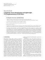
Figure 1: Example of texture image (a) and its associated depth image (b).
textured images, lead to a high-compression efficiency due
to the smooth data representation, as illustrated in Figure 2.
For these advantages, the single view plus depth solution
represents the most promising data representation format
for the near future broadcast 3DTV system. An end-to-
end processing chain for such a system, starting with 3D
acquisition, followed by postproduction, extracting depth
information for 3D, rendering has been investigated by the
European information society technologies (ISTs) project
“advanced three-dimensional television system technolo-
gies” (ATTESTs) [9]. The ATTEST concept outlines different
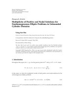
functional buildings blocks, as shown in Figure 3.A3DTV
signal is processed through a chain composed by different
units: the 3D content generation, the 3D video coding, the
transmission, the “virtual” view synthesis, and the display.
In this paper, an alternative method for encoding video-
plus-depth sequences that utilizes a novel joint motion
estimator is presented. Classically, the correlation between
the texture motion vectors and the depth sequence motion
vectors is not exploited in the coding process. One of the
aims of this paper is to reduce the amount of information
for describing the motion of the texture video and the depth
map sequences by sharing one common motion vector field.
Intuitively, the texture video and the depth map sequences
have common characteristics, since they describe the same
scene with the same point of view. For that reason, in both
domains (color-surface structure and distance information)
boundaries coincide and the direction of motion is the
same. Our approach exploits the physical relation between
the motion in both videos, the texture and depth map
videos. However, the disadvantage is that it cannot handle
scenarios containing motion in the Z axis, which is not
perceptible in the texture video, but is present in the depth
map sequence. The correlation between the motion vectors
between the texture video and the depth sequence has already
been exploited in the literature. For example, in [10], the
motion vectors found for the texture video have been shared
to the depth map, without any modification. In [11], H.264 is
used for depth map coding to reduce the motion estimation
complexity of the depth map encoding by using the decoded
texture motion information. This improves basic motion
vector sharing idea with some additional modifications on
the vectors. It requires some bits for motion vectors, but still
it is claimed to be good especially in low bitrates. In our
approach, the motion vector sharing idea is extended, by
introducing into the estimation criterion the minimization
of the two energies, of the texture video, and of the depth
map.
Furthermore, in the literature, the bitrate control scheme
generally fixes for the depth map sequence a percentage of
20% of the texture stream bitrate within MPEG-2 framework
[12]. This value has been proposed, for example, in the
project ATTEST. Considering a separable scheme where
the texture is encoded independently with MPEG-2 (for
backward compatibility with existing TV solutions) and the
depth map with MPEG-4, this percentage can go down to
5–10%. However, this fixed percentage can affect the depth
coding efficiency, and this percentage should also depend
of the specificities of each video. We propose a new bitrate
allocation strategy, which considers both the texture and its
associated per pixel depth information.
The remainder of this paper is structured as follows.
In Section 2, we present the existing work on video-plus-
depth format. The extensions of the video-plus-depth coding
are described in Sections 3 and 4. Section 5 shows the
experimental results. We finally summarize our work in
Section 6.
2. Video-Plus-Depth
3DTV needs specific requirements like high quality, back-
ward compatibility with current digital TV, interactivity,
which can be used to support the autostereoscopic applica-
tion scenarios. The high quality requirement supposes a large
amount of data to be transmitted on the conventional 2D
video channel. In addition, backward compatibility needs to
allow the extraction of 2D information for the existing 2DTV
displays. In the end, 3DTV applications need some kind of
reactivity of the system in relation to user actions. Among
all the potential 3D representation candidates (3D models,
light field, ray space, plane sweep, etc.), video-plus-depth
framework is the most suitable representation for an end-
to-end broadcast 3DTV system in order to fulfill the above
mentioned constraints.
Initially studied in computer vision field, the video-
plus-depth representation provides a texture video and its
associated depth map sequence. The texture video provides
EURASIP Journal on Advances in Signal Processing 3
35
38
41
44
47
50
53
55
PSNR (dB)
0246810
Bitrate (Mbps)
Te x t u r e v i d e o
Depth map sequence
(a) Breakdancers cam0
40
42
44
46
48
50
52
54
PSNR (dB)
24 6810
Bitrate (Mbps)
Te x t u r e v i d e o
Depth map sequence
(b) Ballet cam0
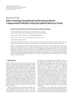
Figure 2: Comparison of the compression efficiency between
texture video and depth map sequence using the MPEG-2 reference
software using a group of pictures (GOP) that consists of 12 frames
with IBBP structure.
the surface, the color, the structure of the scene, whereas the
depth map represents by means of a smoothed gray level
representation the Z-distance between the optical center of
the camera and a point in the visual scene.
Due to the very nature of the depth map picture, the
smoothed gray level representation leads to a much higher
compression efficiency than the texture video, as illustrated
in Figure 2. Thus only a small extra bandwidth is needed
for transmitting the depth map. Moreover, 3DTV based on
depth map permits the synthesizing of new “virtual” views,
utilizing depth map information, as if they were captured
-Display configuration
-User preferences
Multiple user
3DTV
Single user
3DTV
Standard
2DTV
DVB
Transmission
Stereo
camera
Depth
camera
Multi-
camera setup
2D/3D
conversion
3D content production
3D viedo coding
3DTV decoder + DIBR
DVB decoder
Video
Depth
Meta data
.
.
.
.
.
.
.
.
.
.
.
.
.
.
.
Figure 3: The ATTEST 3DTV end-to-end system.
from a new “virtual” camera. Furthermore, this system is not
optimized for a predefined screen size, and so, allows an easy
customization of the depth effect.
MPEG has presented the MPEG-C Part 3 specification,
which standardizes the video-plus-depth coding [8]. This
specification is based on the encoding of 3D content inside
a conventional MPEG-2 transport stream, which includes
the texture video, the depth map sequences, and some
auxiliary data. This standardized solution responds to the
broadcast infrastructure needs. It provides interoperability of
the content, display technology independence, capture tech-
nology independence, backward compatibility, compression
efficiency, and user controlled global depth range.
2.1. Virtual View Synthesis. Considering the end-to-end
system for 3DTV illustrated in Figure 3, at the receiver
side the final 3D images are reconstructed by using DIBR,
utilizing the transmitted reference view enriched with its
associated per pixel depth information. This scheme, also
called 3D image warping in the computer graphics literature
[13], consists in first doing a projection from the 2D original
camera image plane to the 3D coordinates. Thereafter, a
second projection from the 3D coordinates is applied to
the image plane of the desired virtual camera, using the
respective depth values. Due to sharp horizontal changes
in the depth map, the image warping reveals areas that are
occluded in the reference view and become visible in some
virtual views. To deal with this problem, averaging filters or
more complex extrapolation techniques [12]areusedtofill
these occlusions.
We can distinguish two roles for the transmitted refer-
encevideostream.Oneistoconsideritasacenterview,
and so a viewpoint translation and rotation on it will result
in the virtual left and right views. Another configuration
considers the transmitted real view as the right or left view.
So, instead of generating two virtual views at the receiver
side, just one is needed to reconstruct a stereoscopic scheme
4 EURASIP Journal on Advances in Signal Processing
Z
t
x
X
f
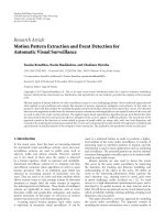
Figure 4: Shift-sensor camera setup: t
x
is the distance between
cameras, f is the focal length of the reference camera, and Z
represents the depth axis.
together with the depth information. In the sequel of this
paper, we will consider that we only transmit the right view.
Of course, this approach has some limitations: the virtual
left view is generated from a double longer translation,
causing more and bigger newly exposed areas. However, the
quality of the right view is not at all affected. Consequently,
the binocular perception is better supported and the depth
sensation is better appreciated with an asymmetric quality
than a reduction of quality in both views, as experimented in
[14, 15].
Considering a system of parallel camera configuration
(with known parameters) to generate stereoscopic content
from the so-called shift-sensor approach (Figure 4), the
warped view is performed by a projection, a horizontal
translation, and a reprojection of pixels. The transformation
that defines the new coordinates in the virtual view (x
virt
, y)
from the reference view at (x
ref
, y) according to depth value
Z is calculated as
x
virt
= x
ref
+
t
x
× f
Z
,(1)
where t
x
is the distance between the reference camera and
the virtual camera (commonly equal to the average human
eyes separation), and f is the focal length of the reference
camera. In this case, a pixel and the associated warped pixel
have the same vertical coordinates due to the chosen camera
configuration.
Preprocessing the depth map allows to reduce the
number and the size of holes created by the warping [16].
Nevertheless, some holes can remain, requiring a last step
of hole filling, consisting in an interpolation of the missing
values [17].
3. Motion Prediction
High compression efficiency is achieved by using motion
estimation and compensation. Temporal redundancies are
removed by estimating the motion between frames in the
sequence and then generating the motion vector field, which
minimizes the temporal prediction error. The motion vectors
(MVs) for temporal prediction reside in the predictive P
frames and the bidirectional B frames. Consequently, in a
Table 1: Percentage of the energy of the motion field vector inside
the interview sequence.
Static object Motion object
Texture 38.87% 61.13%
Depth map 20.01% 79.99%
Table 2: Comparison of the mean value of the correlation
coefficient and the difference value between all the MV and the MV
belonging to the objects in movement.
Correlation
Correlation
with mask
Difference
Difference
with mask
Horizontal
component
0.2003
0.2675
0.3657
0.1790
Ve r t i c a l
component
0.1196
0.1679
0.3387
0.1146
typical GOP for broadcasting purposes having the structure
IBBPBBPBBPBB, the number of coded macroblocks in
temporal predictive mode can reach 40% of the total number
macroblock at low bitrate (as shown in Figure 5), and as a
result, the transmission of motion data consumes a large part
of the bitstream for low-bitrate coders.
The video-plus-depth stream contains usually twice this
number of motion vector fields, respectively, for the texture
and for the depth temporal prediction. Instead of working
on the efficiency of the two motion vectors, in order to
minimize the prediction error in both cases, we show that
only one motion vector field can be transmitted inside the
global stream, since the motion in both videos is correlated.
3.1. Motion Correlation. As the texture video and the depth
map are spatially correlated, the motion vectors in the two
sequences should also be correlated.
To prove this hypothesis, one experiment has been
performed. The observation of the motion vectors confirms
the correlated location of the motion information. Indeed in
Figure 6, the similarities of objects boundaries in the texture
and in the depth map are highlighted. Actually, the two
videos describe the same scene with the same point of view.
Consequently, the motion contained in the two sequences
is similar at the same spatial location, and takes the similar
directions (Figure 8). As expected, the motion analysis, the
correlation coefficient, and the average difference between
the MV shown in Figure 9 confirm the correlation between
the MV.
Moreover, a second experiment is performed only on
the MV of the object in movement by means of the
associated segmentation mask sequence (Figure 10). The
mask sequence allows to easily identifies the different layered
objects at different depth levels. Indeed, Tab le 1 confirms that
the energy of the MV of the characters are more important.
As shown in the Figure 11, the correlation between the MV
of the texture and the MV of the depth map gains a small
amelioration in the correlation coefficient and a reduction in
the average difference value as shown in Ta bl e 2.
EURASIP Journal on Advances in Signal Processing 5
10
20
30
40
50
60
%ofmotionmacroblocks
0246810
Bitrate (Mbps)
Te x t u r e
Depth map
(a) Ballet sequence
20
25
30
35
40
45
50
%ofmotionmacroblocks
0246810
Bitrate (Mbps)
Te x t u r e
Depth map
(b) Breakdancers sequence
10
20
30
40
50
60
70
%ofmotionmacroblocks
02468
Bitrate (Mbps)
Te x t u r e
Depth map
(c) Interview sequence
20
25
30
35
40
45
50
55
60
%ofmotionmacroblocks
02468
Bitrate (Mbps)
Te x t u r e
Depth map
(d) Orbi sequence
Figure 5: Percentage of the coded predictive (forward and backward) macroblocks inside the video sequence.
(a) (b)
Figure 6: Edges in the texture image (left) and the associated depth image edges (right) from the sequence Ballet.
6 EURASIP Journal on Advances in Signal Processing
(a) (b)
Figure 7: Example of texture image (a) and its associated depth image (b) from the frame 109 of the sequence interview. The two policemen
are shaking hands which yields a lot of motion vectors.
3.2. Joint Motion Estimation. Among the various techniques
for motion estimation (ME), block matching has been
adopted in all international standards for video coding due
to its simplicity and effectiveness. In this method, each frame
is partitioned in nonoverlapping blocks of pixels, and each
block is predicted from a block of equal size in the reference
frame. The MV of a block is estimated by considering the best
matching block, corresponding in general to the minimum
mean square error (MSE) or mean absolute error (MAE) [18]
with respect to the previous frame. Let F
t
(x, y) denote the
image intensity of the tth frame at the spatial location (x, y).
The vector (v
x
, v
y
)mapspointsinthecurrentframeF
t+1
to
their corresponding locations in the previous frame F
t
.For
illustration, MSE is defined as follows:
MSE
=
1
N
2
N
x=0
N
y=0
F
t+1
(x, y) −F
t
x + v
x
, y + v
y
2
. (2)
In Section 2, we argued about the need to share the MV by
encoding and transmitting only one motion field for both
the texture and depth videos. That leads to account for both
the distortion in texture and depth map videos by defining
a new motion estimation, where the distortion criterion to
minimize is this time defined jointly for the video texture and
the depth map as follows:
MSE
joint
= αMSE
depth
+(1−α)MSE
texture
,(3)
where α
∈ [0, 1] controls the relative importance given to
the depth and to the texture for this estimation procedure.
According to the proposed distortion metric, the resulting
MV field is used for the two streams, and then encoded only
once. The value α
= 0 is a particular case already studied
in [10], where only the MV from the texture information
is considered to encode both the texture and the depth
map sequences. In our method, we generalize this concept
and investigate the problem of estimating a motion field
which can reduce the temporal correlation as well for the
depth information as for the texture data, by means of the
joint estimation criterion. In the experiments, we tune the
parameter α to find the optimal value depending on the
content of the sequence.
3.3. Motion Sharing. Once the common MV is found, it
has to be encoded for transmission. The motion field used
to encode both the texture and the depth map sequences
is placed in the texture bitstream, to ensure the required
backward compatibility with current TV set-top boxes.
As illustrated in Figure 12, the MVs are shared and
only sent once in the global video-plus-depth stream.
Consequently, this strategy allows more bandwidth resources
to the depth map residues. Moreover, it overcomes the
imperfect match between the two MV fields. In fact, the
correlation error is less significant compared with the gain
in bandwidth.
4. Content Aware Bitrate Allocation
In this section, we consider the problem of finding a rate-
distortion allocation strategy, which may jointly optimize
the resulting video quality and the required bitrate sharing
between the texture and depth map data.
To this end, for each GOP the bits are allocated taking
into account the ratio of the variances of the pictures in the
texture video and the depth map sequence. For the P and the
B frames, this variance is computed on the displaced frame
difference (DFD), defined as
ΔF
t
(x, y) = F
t+1
(x, y) −F
t
(x + v
x
, y + v
y
)(4)
with (v
x
, v
y
) being the MV which minimizes the MSE
measure defined in (3). The variance of this DFD is given
by
σ
2
v
x
,v
y
=
1
N
2
N
x=0
N
y=0
ΔF
t
v
x
,v
y
(x, y) −ΔF
t
v
x
,v
y
2
,(5)
where
ΔF
t
v
x
,v
y
denotes its average value, that is,
ΔF
t
v
x
,v
y
=
N
x=0
N
y=0
ΔF
t
(x, y). (6)
EURASIP Journal on Advances in Signal Processing 7
0
5
10
15
20
25
30
35
Macroblock number
010203040
Macroblock number
MV texture
MV depth
(a) Motion vector field
5
10
15
Macroblock number
10 15 20 25
Macroblock number
MV texture
MV depth
(b) Zoom on the field
Figure 8: Example of motion vector field from the frame 109 of the
sequence interview (Figure 7).
4.1. Bit Allocation Strategy. Finding the optimal rate alloca-
tion between the texture and the depth map is a Lagrangian
optimization problem, with a cost function J involving the
distortion D weighted by the number of bits R
c
and R
d
,
respectively, associated with the texture and the depth map.
By using a Lagrange multiplier λ [19], this yields
min
{J},whereJ = D + λ(R), (7)
where the Lagrangian parameter λ>0, if judiciously applied,
can provide significant benefits.
Introducing the rate-distortion model at high resolution
D(R)[19]:
D(R)
= aσ
2
2
−2R
,(8)
where a is a parameter depending on the distribution of the
source, one can write the global distortion as
D(R)
= D
c
+ D
d
= a
d
σ
2
d
2
−2R
d
+ a
c
σ
2
c
2
−2R
c
,(9)
where a
c
, a
d
are constants associated with the distribution of
thetextureanddepthmap.
The needed bitrate to encode each stream is function
of the global bitrate R and the variance of the composing
streams, texture, and depth map, as follows:
R
c
=
R
2
+
1
2
log
2
σ
c
σ
d
,
(10)
R
d
=
R
2
+
1
2
log
2
σ
d
σ
c
,
(11)
where σ
c
, σ
d
are, respectively, the standard deviations of the
texture and depth map.
With the variance of a frame defined in (5), we can
estimate the average number of bits allocated for each stream
composing the global video-plus-depth stream.
5. Experimental Results and Discussion
Our experiments evaluate the proposed motion estimation
and bitrate allocation methods on two types of sequences
providing a conventional video enriched with a depth map
sequence. The first type contains two sequences: “Breakdan-
ders” and “Ballet” (1024
× 768) at 15 fps [20]. The depth
maps of these sequences have been computed using a stereo
matching algorithm. The second type contains the sequences
“Interview” and “Orbi” (720
× 576) at 25 fps [21], where the
depth information is captured directly from the so-called Z
cam camera.
According to the MPEG-C Part3 specifications, and
under constraints that the same encoder is used as well for
the texture and the depth map, the experiments have been
done with the MPEG-2 reference software. An IBBP GOP
of 12 pictures was used for the configuration of the coder
software.
One of the various MPEG2 industrial applications can
be the storage on DVD support or the transmission over
the digital broadcast using the DVB standard. The used
bitrate has to satisfy at least the quality and the resolution
of the picture for that an average viewer does not perceive
any compression lossy data effect (compression artifacts,
block effects, etc.). Firstly, in DVD case, considering an
SD resolution (720
× 576) at 25 fps, the bitrate is between
4 Mbps and 8 Mbps, that is, 0.39 bpp and 0.77 bpp. Still in
SD resolution, the digital television channels are transmitted
using mostly a bitrate between 2 Mbps and 8Mbps, that is,
0.19 bpp and 0.77 bpp [22]. According to these values, the
8 EURASIP Journal on Advances in Signal Processing
0
0.05
0.1
0.15
0.2
0.25
0.3
Correlation
0 102030405060708090100
Frame number
(a) Ballet-plus-depth correlation
−1
−0.5
0
0.5
1
1.5
2
Average difference
0 102030405060708090100
Frame number
(b) Ballet-plus-depth average difference
−0.05
0
0.05
0.1
0.15
0.2
0.25
Correlation
0 102030405060708090100
Frame number
(c) Breakdancers-plus-depth correlation
−3
−2
−1
0
1
2
3
Average difference
0 102030405060708090100
Frame number
(d) Breakdancers-plus-depth average difference
−0.2
0
0.2
0.4
0.6
0.8
Correlation
0 50 100 150 200 250
Frame number
(e) Interview-plus-depth correlation
−1
−0.5
0
0.5
1
1.5
Average difference
0 50 100 150
200
250
Frame number
(f) Interview-plus-depth average difference
−0.1
0
0.1
0.2
0.3
0.4
0.5
0.6
Correlation
0 20 40 60 80 100 120
Frame number
Horizontal component
Ve r t i c a l c o m p on en t
(g) Orbi-plus-depth correlation
−6
−4
−2
0
2
4
6
Average difference
0 20 40 60 80 100 120
Frame number
Horizontal component
Ve r t i c a l c o m p on en t
(h) Orbi-plus-depth average difference
Figure 9: Motion vector analysis: correlation and average difference between the MV of the texture and the MV of the depth map.
EURASIP Journal on Advances in Signal Processing 9
(a) (b)
Figure 10: Example of texture image (a) and its associated mask image (b) from the frame 109 of the sequence interview. The two policemen
are shaking hands which yields a lot of MV.
−0.2
0
0.2
0.4
0.6
0.8
1
Correlation
0 50 100 150 200 250
Frame number
Horizontal component
Ve r t i c a l c o m p on en t
(a) Interview-plus-depth correlation
−1
−0.5
0
0.5
1
1.5
Average difference
0 50 100 150 200 250
Frame number
Horizontal component
Ve r t i c a l c o m p on en t
(b) Interview-plus-depth average difference
Figure 11: Motion vector analysis only on object in movement in the scene.
Te x t u r e s t r e a m
MV
MV
Te x t u r e
Depth map
Depth map stream
(a) Independent motion vector
Te x t u r e s t r e a m
MV
Te x t u r e
Depth map
Depth map stream
(b) Shared motion vector
Figure 12: Different strategies for MV encoding: (a) separate MV
for texture and depth map and (b) a common MV field for texture
and depth sequences.
test sequences are encoded, according to their own resolution
and frame rate, in respect of the bitrate range used in digital
content industry.
Figure 13 shows the PSNR of the texture video and of the
depth map sequence when the parameter α varies between 0
and 1. One can remark a sensible improvement of the depth
map reconstruction (more than 1 dB), for a small reduction
in the texture video quality (between 0.4–0.8 dB), when using
the joint estimation criterion.
Inordertofindtheoptimalvalueofα for each test
sequence, we tune the parameter and provide PSNR analysis
of the reconstructed (virtual) sequence as illustrated in
Figure 14. The depth map bitrate is arbitrarily fixed to 20% to
the texture bitrate. The curves highlight a value close to α
=
0.2, α = 0.0, and α = 0.6 as the best value for, respectively,
the sequence “Ballet,” “Breakdancers,” and “Interview.” This
shows that estimating the MV only on the texture video does
not lead to the best reconstruction of the virtual sequence,
and the proposed trade off can largely improve the results.
As defined in (10), Tab le 3 shows for different sequences
the variance ratio value which between texture video and
depthmapsequenceforeachtypeofframeinaGOP.
Except for the “Breakdancers” sequence, the main variation
in allocation affects the I frame. As a result, more bits are
allocated to the texture stream than the depth map stream.
Considering the depth map bitrate equal to 20% of the
texture bitrate, Figure 15 shows the resulting “virtual” PSNR.
The joint motion estimation has been coupled with the new
bitrate allocation. The results show better performance at
high bitrate (between 0.5–1.5 dB) for a small reduction at low
bitrate (between 0.2–1 dB).
10 EURASIP Journal on Advances in Signal Processing
32
34
36
38
40
42
44
PSNR (dB)
12345678910
Bitrate (Mbps)
(a) Ballet texture
34
36
38
40
42
44
46
PSNR (dB)
0.511.52
Bitrate (Mbps)
(b) Ballet depth map
30
32
34
36
38
40
42
PSNR (dB)
12345678910
Bitrate (Mbps)
(c) Breakdancers texture
34
36
38
40
42
44
46
PSNR (dB)
0.811.21.41.61.82
Bitrate (Mbps)
(d) Breakdancers depth map
28
30
32
34
36
38
40
42
44
PSNR (dB)
02468
Bitrate (Mbps)
α
= 0
α
= 0.2
α
= 0.4
α
= 0.6
α
= 0.8
α
= 1
(e) Interview texture
36
38
40
42
44
46
48
PSNR (dB)
0.40.60.811.21.41.8
Bitrate (Mbps)
α
= 0
α
= 0.2
α
= 0.4
α
= 0.6
α
= 0.8
α
= 1
(f) Interview depth map
Figure 13: PSNR comparison with a joint MSE, for a variable parameter α ∈ [0,1].
EURASIP Journal on Advances in Signal Processing 11
30
31
32
33
34
35
Reconstructed PSNR (dB)
246810
Bitrate (Mbps)
(a) “Virtual” Ballet sequence
31
32
33
34
35
36
37
38
39
Reconstructed PSNR (dB)
246810
Bitrate (Mbps)
(b) “Virtual” Breakdancers sequence
28
30
32
34
36
38
Reconstructed PSNR (dB)
02468
Bitrate (Mbps)
α
= 0
α
= 0.2
α
= 0.4
α
= 0.6
α
= 0.8
α
= 1
(c) “Virtual” Interview sequence
Figure 14: Search of the optimal α by comparison of the
reconstructed “virtual” video PSNR. The depth map bitrate is equal
to 20% of the texture bitrate.
Table 3: Average variance ratio between the texture video and the
depth map sequence.
σ
c
/σ
d
IPB
Breakdancers 0.3266 0.9414 1.0891
Ballet 0.6513 3.9866 4.3257
Interview 0.5646 1.0871 1.1159
Table 4: Average MOS provided numerical indication of the
perceived quality. MOS value is expressed between 1 and 5, where 1
refers to lowest quality, and 5 to a highest quality.
Reference MOS Proposed MOS
Ballet (2.5 Mbps) 2.7 2.4
Ballet (7 Mbps) 3.6 4.2
Breakdancers (2.5 Mbps) 2.8 3.4
Breakdancers (7 Mbps) 4.1 4.2
Interview (1.5 Mbps) 1.4 1.3
Interview (5 Mbps) 3.8 3.9
Since 3D perception depends heavily on the stereoscopic
vision of two sequences, the transmitted texture video
and the reconstructed “virtual” sequence, it is difficult to
evaluate the 3D perceived quality only by means of an
objective evaluation model like the PSNR. Thus an additional
validation is proposed through an subjective evaluation. For
this, the perceived quality and the depth perception are
conducted using the double stimulus continuous quality
scale method (DSCQS) test methodology [23]. Nonexperts
and inexperienced accessors are providing their opinion
of the video quality and the video depth perception. The
experiment gathers 15 accessors using the autostereoscopic
Sharp LL-151-3D LCD Monitor. Average mean opinion score
(MOS), according to the ITU-R Recommendation BT.500-
10, is given in Ta b le 4. The results obtained confirms the
objective results. It is shown an overall amelioration of
the proposed method compare to the conventional MPEG2
bitrate allocation with an advantageous amelioration in high
bitrate.
6. Conclusion and Future Work
This paper presented a novel method for the coding the
video-plus-depth data by means of a joint estimation of
the MV field for the texture motion information and the
depth map sequence. Furthermore, we developed a bitrate
allocation strategy between the texture and depth map
stream based on a rate-distortion criterion. According to the
MPEG-C Part 3 specifications, the texture video was encoded
in an MPEG-2 stream for backward-compatibility purposes.
In future work, we aim at developing a new model for the
rate-distortion optimization, which can take into account the
quality of the reconstructed virtual view and also building a
global distortion based on subjective quality.
12 EURASIP Journal on Advances in Signal Processing
38
39
40
41
42
43
44
45
PSNR (dB)
0246810
Bitrate (Mbps)
(a) “Transmitted” Ballet sequence
31
32
33
34
35
36
Reconstructed PSNR (dB)
0246810
Bitrate (Mbps)
(b) “Virtual” Ballet sequence
34
35
36
37
38
39
40
41
PSNR (dB)
0246810
Bitrate (Mbps)
(c) “Transmitted” Breakdancers sequence
33
34
35
36
37
38
39
Reconstructed PSNR (dB)
0246810
Bitrate (Mbps)
(d) “Virtual” Breakdancers sequence
30
35
40
45
PSNR (dB)
02468
Bitrate (Mbps)
Reference
Proposed
(e) “Transmitted” Interview sequence
30
32
34
36
38
40
Reconstructed PSNR (dB)
02468
Bitrate (Mbps)
Reference
Proposed
(f) “Virtual” Interview sequence
Figure 15: Resulting reconstructed PSNR of the “virtual” video using the new bitrate allocation with the PSNR of the other stereo view.
Depth map bitrate equals 20% of the texture bitrate.
EURASIP Journal on Advances in Signal Processing 13
References
[1] K. Yamamoto, M. Kitahara, H. Kimata, et al., “Multiview video
coding using view interpolation and color correction,” IEEE
Transactions on Circuits and Systems for Video Technology, vol.
17, no. 11, pp. 1436–1449, 2007.
[2] S U. Yoon and Y S. Ho, “Multiple color and depth video
coding using a hierarchical representation,” IEEE Transactions
on Circuits and Systems for Video Technology, vol. 17, no. 11,
pp. 1450–1460, 2007.
[3] P. Merkle, A. Smolic, K. M
¨
uller, and T. Wiegand, “Efficient
prediction structures for multiview video coding,” IEEE
Transactions on Circuits and Systems for Video Technology, vol.
17, no. 11, pp. 1461–1473, 2007.
[4] M. Flierl, A. Mavlankar, and B. Girod, “Motion and disparity
compensated coding for multiview video,” IEEE Transactions
on Circuits and Systems for Video Technology, vol. 17, no. 11,
pp. 1474–1484, 2007.
[5] S. Shimizu, M. Kitahara, H. Kimata, K. Kamikura, and Y.
Yashima, “View scalable multiview video coding using 3D
warping with depth map,” IEEE Transactions on Circuits and
Systems for Video Technology, vol. 17, no. 11, pp. 1485–1495,
2007.
[6] X. San, H. Cai, J G. Lou, and J. Li, “Multiview image coding
based on geometric prediction,” IEEE Transactions on Circuits
and Systems for Video Technology, vol. 17, no. 11, pp. 1536–
1548, 2007.
[7] A. Smolic, K. Mueller, N. Stefanoski, et al., “Coding algorithms
for 3DTV—a survey,” IEEE Transactions on Circuits and
Systems for Video Technology, vol. 17, no. 11, pp. 1606–1621,
2007.
[8] ISO/IEC JTC 1/SC 29/WG 11, “Committee draft of ISO/IEC
23002-3 auxiliary video data representations,” WG 11 Doc.
N8038. Montreux, Switzerland, April 2006.
[9] C. Fehn, “A 3D-TV system based on video plus depth
information,” in Proceedings of the 37th Asilomar Conference on
Signals, Systems and Computers, vol. 2, pp. 1529–1533, Pacific
Grove, Calif, USA, November 2003.
[10] S. Grewatsch and E. M
¨
uller, “Sharing of motion vectors
in 3D video coding,” in Proceedings of IEEE International
Conference on Image Processing (ICIP ’04), vol. 5, pp. 3271–
3274, Singapore, October 2004.
[11] H. Oh and Y S. Ho, “H.264-based depth map sequence coding
using motion information of corresponding texture video,”
in Proceedings of the 1st Pacific Rim Symposium on Advances
in Image and Video Technology (PSIVT ’06), pp. 898–907,
Hsinchu, Taiwan, December 2006.
[12] C. Fehn, “Depth-image-based rendering (DIBR), compression
and transmission for a new approach on 3D-TV,” in Stereo-
scopic Displays and Virtual Reality Systems XI, vol. 5291 of
Proceedings of SPIE, pp. 93–104, San Jose, Calif, USA, January
2004.
[13] R. I. Hartley and A. Zisserman, Multiple View Geometry in
Computer Vision, Cambridge University Press, Cambridge,
UK, 2nd edition, 2004.
[14] L. B. Stelmach, W. J. Tam, D. V. Meegan, A. Vincent, and P.
Corriveau, “Human perception of mismatched stereoscopic
3D inputs,” in Proceedings of IEEE International Conference
on Image Processing (ICIP ’00), vol. 1, pp. 5–8, Vancouver,
Canada, September 2000.
[15] P. Seuntiens, L. Meesters, and W. Ijsselsteijn, “Perceived quality
of compressed stereoscopic images: effects of symmetric
and asymmetric JPEG coding and camera separation,” ACM
Transactions on Applied Perception, vol. 3, no. 2, pp. 95–109,
2006.
[16] I. Daribo, C. Tillier, and B. Pesquet-Popescu, “Distance
dependent depth filtering in 3D warping for 3DTV,” in
Proceedings of IEEE International Workshop on Multimedia
Signal Processing (MMSP ’07), pp. 312–315, Crete, Greece,
October 2007.
[17] W. R. Mark, L. McMillan, and G. Bishop, “Post-rendering 3D
warping,” in Proceedings of the Symposium on Interactive 3D
Graphics, pp. 7–16, Providence, RI, USA, April 1997.
[18] M. Nalasani and W. D. Pan, “Performance evaluation of
MPEG-2 codec with accurate motion estimation,” in Proceed-
ings of the 37th Annual Southeastern Symposium on System
Theory (SSST ’05), pp. 287–291, Tuskegee, Ala, USA, March
2005.
[19] G. J. Sullivan and T. Wiegand, “Rate-distortion optimization
for: video compression,” IEEE Signal Processing Magazine, vol.
15, no. 6, pp. 74–90, 1998.
[20] “Sequence microsoft ballet and breakdancers,” 2004
/>[21] C. Fehn, K. Sch
¨
u
¨
ur, I. Feldmann, P. Kauff, and A. Smolic,
“Distribution of ATTEST test sequences for EE4 in MPEG
3DAV,” in MPEG Meeting - ISO/IEC JTC1/SC29/WG11,
MPEG02/M9219, Awaji Island, Japan, December 2002.
[22] Digital bitrate, />[23] ITU, “Methodology for the subjective assessment of the qual-
ity of television pictures,” ITU-R Recommendation BT.500-10
(1974-2002), />