Báo cáo hóa học: " Research Article Complexity-Aware Quantization and Lightweight VLSI Implementation of FIR Filters" docx
Bạn đang xem bản rút gọn của tài liệu. Xem và tải ngay bản đầy đủ của tài liệu tại đây (1.42 MB, 14 trang )
Hindawi Publishing Corporation
EURASIP Journal on Advances in Signal Pr ocessing
Volume 2011, Article ID 357906, 14 pages
doi:10.1155/2011/357906
Research Ar ticle
Complexity-Aware Quantization and Lig htweight
VLSI Implementation of FIR Filters
Yu-Ting Kuo,
1
Tay-Jy i Lin,
2
and C hih-Wei Liu
1
1
Department of Electronics Engineering, National Chiao Tung University, Hsinchu 300, Taiwan
2
Department of Computer Science and Information Engineering, National Chung Cheng University, Chiayi 621, Taiwan
Correspondence should be addressed to Tay-Jyi Lin,
Received 1 June 2010; Revised 28 October 2010; Accepted 4 January 2011
Academic Editor: David Novo
Copyright © 2011 Yu-Ting Kuo et al. This is an open access article distributed under the Creative Commons Attribution License,
which permits unrestricted use, distribution, and reproduction in any medium, provided the original work is properly cited.
The coefficient values and number representations of digital FIR filters have significant impacts on the complexity of their
VLSI realizations and thus on the system cost and performance. So, making a good tradeoff between implementation costs
and quantization errors is essential for designing optimal FIR filters. This paper presents our complexity-aware quantization
framework of FIR filters, which allows the explicit tradeoffs between the hardware complexity and quantization error to facilitate
FIR filter design exploration. A new common subexpression sharing method and systematic bit-serialization are also proposed for
lightweight VLSI implementations. In our experiments, the proposed framework saves 49%
∼ 51% additions of the filters with
2’s complement coefficients and 10%
∼ 20% of those with conventional signed-digit representations for comparable quantization
errors. Moreover, the bit-serialization can reduce 33%
∼ 35% silicon area for less timing-critical applications.
1. Introduction
Finite-impulse response (FIR) [1]filtersareimportant
building blocks of multimedia signal processing and wire-
less communications for theiradvantagesoflinearphase
and stability. These applications usually have tight area
and power constraints due to battery-life-time and cost
(especially for high-volume products). Hence, multiplier-
less FIR implementations are desirable because the bulky
multipliers are replaced w ith shifters and adders. Various
techniques have been proposed for reducing the number
of additions (thus the complexity) through exploiting the
computation redundancy in filters. Voronenko and Püschel
[2] have classified these techniques into four types: digit-
based encoding (such as canonic-signed-digit, CSD [3]),
common subexpression elimination (CSE) [4–10], graph-
based approaches [2, 11–13],andhybridalgorithms[14, 15].
Besides, the differential coefficient method [16–18]isalso
widely used for reducing the additions in FIR filters. These
techniques a re effective for reducing FIR filters’ complexities
but they can only be applied after the coefficients have been
quantized. In fact, the required number of additions strongly
depends on the discrete coefficient values, and therefor e
coefficient quantization should take the filter complexity into
consideration.
In the literature, many works [19–29] have been pro-
posed to obtain the discrete coefficient values such that
the incurred additions are minimized. These works can be
classified into two categories. The first one [19–23]isto
directly synthesize the discrete coefficients by formulating
the coefficient design as a mixed integer linear program-
ming (MILP) problem and often adopts the branch and
bound technique to find the optimal discrete values. The
works i n [19–23] obtain very good result; however, they
require impractically long times for opt imizing high-order
filters with wide wordlengths. Therefore, some researchers
suggested to first design the optimum real-valued coefficients
and then quantize them with the consideration of filter com-
plexity [24–29]. We call these approaches the quantization-
based methods. The results in [24–29] show that great
amount of additions can be saved by exploiting the scaling
factor exploration and local search in the neighbor of the
real-valued coefficients.
The aforementioned quantization methods [24–
29]are
effective for minimizing the complexity of the quantized
coefficients, but most of them cannot explicitly control
2 EURASIP Journal on Advances in Signal Processing
the number of additions. If designers want to improve
the quantization error with the price of exactly one more
addition, most of the above methods cannot efficiently
make such a tradeoff. Some methods (e.g ., [19, 21, 22])
can control the number of nonzero digits in each coeffi-
cient, but not the total number of nonzero digits in all
coefficients. Li’s approach [28]offers the explicit control
over the total number of nonzero digits in all coefficients.
However, his approach does not consider the effect of CSE
and could only roughly estimate the addition count of the
quantized coefficients, which thus might be suboptimal.
These facts motivate the authors to develop a complexity-
aware quantization framework in which CSE is considered
and the number of additions can be efficiently traded
for quantization errors. In the proposed framework, we
adopt the successive coefficient approximation [28]and
extend it by integrating CSE into the quantization proc ess.
Hence, our approach can achieve better filter quality with
fewer additions, and more importantly, it can explicitly
control the number of additions. This feature provides
efficient tradeoffs between the filter’s quality and complexity
and can reduce the design iterations between coefficient
optimization and computation sharing exploration. Though
the quantization met hods in [27, 29] also consider the effect
of CSE; however, their common subexpressions are limited
to 101 and 101
only. The proposed quantization frame-
work has no such limitation and is more comprehensible
because of its simple structure. Besides, we also present
an improved common subexpression sharing to save more
additions and a systematic VLSI design for low-complexity
FIR filters.
The rest of this paper is organized as follows. Sec-
tion 2 briefly reviews some existing techniques that are
adopted in our framework. Section 3 describes the proposed
complexity-aware quantization as well as the improved com-
mon subexpression sharing. The lightweight VLSI imple-
mentation of FIR filters is presented in S ection 4.Section5
shows the simulation and experimental results. Section 6
concludes this work.
2. Preliminary
This section presents some background knowledge of the
techniques that are exploited in the proposed complexity-
a ware quantization framework. These techniques include
the successive coefficient approximation [28]andCSE
optimizations [30].
2.1. Successive Coefficient Approximation. Coefficient quan-
tization strongly affects the quality and complexity of FIR
filters, especially for the multiplierless implementation. Con-
sidera4-tapFIRfilterwiththecoefficients: h
0
= 0.0111011,
h
1
= 0.0101110, h
2
= 1.0110011, and h
3
= 0.0100110,
which are four fractional numbers represented in the 8-bit
2’s complement format. The filter output is computed as the
inner product
y
n
= h
0
· x
n
+ h
1
· x
n−1
+ h
2
· x
n−2
+ h
3
· x
n−3
. (1)
Additions and shifts can be substituted for the multiplica-
tions as
y
n
= x
n
»2 + x
n
»3 + x
n
»4 + x
n
»6 + x
n
»7
+ x
n−1
»2 + x
n−1
»4 + x
n−1
»5 + x
n−1
»6
− x
n−2
+ x
n−2
»2 + x
n−2
»3 + x
n−2
»6 + x
n−2
»7
+ x
n−3
»2 + x
n−3
»5 + x
n−3
»6,
(2)
where “»” denotes the arithmetic right shift with sign
extension ( i.e., equivalent to a division operation). Each
filter output needs 16 additions (including subtractions) and
16 shifts. Obviously, the nonzero terms in the quantized
coefficients determine the number of additions and thus the
filter’s complexity.
Quantizing the coefficients straightforwardly does not
consider the hardware complexity and cannot make a good
tradeoff between quantization errors and filter complexities.
Li et al. [28]proposedaneffective alternative, which
successively approximates the ideal coefficients (i.e., the real-
valued ones) by allocating nonzero terms one by one to
the q uantized coefficients. Figure 1(a) shows Li’s approach.
The ideal coefficients (IC) are first normalized so that the
maximum magnitude is one. An optimal scaling factor (SF)
is then searched within a tolerable gain range (the searching
range from 0.5 to 1 is adopted in [28]) to collectively settle
the coefficients into the quantization space. For each SF, the
quantized coefficients are initialized to zeros, and a signed-
power-of-two (SPT) [28] term is allocated to the quantized
coefficient that differs most from the correspondent scaled
and normalized ideal coefficient (NIC) until a predefined
budget of nonzero terms is exhausted. Finally, the best result
with the optimal SF is chosen. Figure 1(b) is an illustrating
example of successive approximation when S F = 0.5. The
approximation terminates whenever the differences between
all ideal and quantized coefficient pairs are less than the
precision (i.e., 2
−w
, w denotes the wordlength), because the
quantization result cannot be improved an ymore.
Note that the approximation strategy can strongly affect
the quantization quality. We will show in Section 5 that
approximation with SPT coefficients significantly reduces the
complexity then approximation with 2’s complement coeffi-
cients. Besides, we will also show that the SPT coefficients
have comparable performance to the theoretically optimum
CSD coding. Hereafter, we use the approximation with SPT
terms, unless otherwise specified.
2.2. Common Subexpression Elimination (CSE). Common
subexpr ession elimination can significantly reduce the com-
plexity of FIR filters by removing the redundancy among
the constant multiplications. The common subexpressions
can be eliminated in several ways, that is, across coefficients
(CSAC) [30], within coefficients (CSWC) [30], and across
iterations (CSAI) [31]. The following example illustrates the
elimination of CSAC. Consider the FIR filter example in
(2). The h
0
and h
2
multiplications, that is, the first and
the third rows in (2), have four terms with identical shifts.
EURASIP Journal on Advances in Sig nal Processing 3
1: Normalize IC so that the maximum coefficient magnitude is 1
2: SF
= lower bound
3: WHILE (SF < upper bound)
4:
{
Scale the normalized IC with SF
5: WHILE (budget >0 & the largest difference between QC & IC >2
−
w
)
6: Allocate an SPT term to the QC that differs most from the scaled NIC
7: Evaluate the QC result
8: SF
=
SF + 2
−
w
}
9: Choose the best QC result
(a)
IC
=
[0.26 0.087 0.011]0.131
Normalized IC (NIC)
=
[1 0.5038 0.3346 0.0423], NF
=
max(IC)
=
0.26
When SF
=
0.5
Scaled NIC
=
[0.5 0.2519 0.1673 0.0212]
QC
0
=
[0000]
QC
1 = [0.5 000]
QC
2 = [0.5 0.25 00]
QC
3
=
[0.5 0.25 0.125 0]
QC
4
=
[0.5 0.25 0.15625 0]
QC
5
=
[0.5 0.25 0.15625 0.015625]
(b)
Figure 1: Quantization by successive approximation (a) algorithm (b) example.
0011 011
0010 110
0010 110
00001000
00101110
00100110
00110011
b
7
b
6
b
5
b
4
b
2
b
1
b
0
h
0
h
1
h
2
h
3
h
0
h
1
h
2
h
3
x
0
+ x
2
−1011
1
1
0
b
3
b
7
b
6
b
5
b
4
b
2
b
1
b
0
b
3
0011
−10000000
Figure 2: CSAC extraction and elimi nation.
Restructuring (2) by first adding x
n
and x
n−2
eliminates the
redundant CSAC as
y
n
=
(
x
n
+ x
n−2
)
»2 +
(
x
n
+ x
n−2
)
»3 +
(
x
n
+ x
n−2
)
»6
+
(
x
n
+ x
n−2
)
»7 + x
n
»4 − x
n−2
+ x
n−1
»2 + x
n−1
»4 + x
n−1
»5 + x
n−1
»6
+ x
n−3
»2 + x
n−3
»5 + x
n−3
»6,
(3)
where the additions and shifts for an output are reduced to 13
and 12, respectively. The extraction and elimination of CSAC
can be more concisely manipulated in the tabular form as
depicted in Figure 2.
On the other hand, bit-pairs with identical bit displace-
ment within a coefficient or a CSAC term are recognized
as CSWC, which can also be eliminated for computation
reduction. For example, the subexpression in (3)canbe
simplified as (x
02
+x
02
»1)»2+(x
02
+x
02
»1)»6, where x
02
stands
for x
n
+ x
n−2
, to further reduce one addition and one shift.
The CSE quality of CSAC and CSWC strongly depends on
the elimination order. A steepest-descent heuristic is applied
in [30] to reduce the search space, where the candidates
with more addition reduction are removed first. One-level
look-ahead is applied to further distinguish the candidates of
the same weight. CSWC elimination is performed in a similar
way afterwards because it incurs shift operations and results
in intermediate variables with higher precision. Figure 3
shows the CSE algor ithm for CSAC and CSWC [30].
It should be noted that an input datum x
n
is reused for L
iterations in an L-tap direct-form FIR filter, which introduces
another subexpression sharing [31]. For example, x
n
+x
n−1
+
x
n−2
+x
n−3
can be restructured as (x
n
+x
n−1
)+z
−2
·(x
n
+x
n−1
)
to reduce one addition, which is referred to as the CSAI
elimination. However, implementing z
−2
is costly because
the area of a w-bit register is comparable to a w-bit adder.
Therefore, we do not consider CSAI in this paper.
Traditionally, CSE optimization and coefficient quantiza-
tion are two separate steps. For example, we can first quantize
the coefficients via the successive coefficient approximation
and then apply CSE on the quantized coefficients. However,
as stated in [21], such two-stage approach has an apparent
drawback. That is, the successive coefficient approximation
method may find a discrete coefficient set that is optimal
in terms of the number of SPT terms, but it is not
optimal in terms of the number of additions after CSE
is applied. Moreover, designers cannot explicitly control
the number of additions of the quantized filters during
quantization. Combining CSE with quantization process can
help designers find the truly low-complexity FIR filters but
is not a trivial task. In the next section, we will present a
complexity-aware quantization framework which seamlessly
integrates the successive approximation and CSE together.
4 EURASIP Journal on Advances in Signal Processing
Eliminate zero coefficients
Merge coefficients with the same value (e.g. linear-phase FIR)
Construct acoefficient matrix of size N
×
W//N:#ofcoefficients for CSE, W: word-length
WHILE (highest weight > 1) // CSAC elimination
{
Find the coefficient pair with the highest weight
Update the coefficient matrix
}
FOR each row in the coefficient matrix // CSWC elimination
{Find bit-pairs with identical bit displacement
Extract the distances between those bit-pairs
Update the coefficient matrix and record the shift information
}
Output the coefficient matrix
Figure 3: CSE algorithm for CSAC and CSWC [30].
3. Proposed Complexity-Aware
Quantization Framework
In the proposed complexity-aware quantization framework,
we try to quantize the real-valued coefficients such that
the quantization error is minimized under a predefined
addition budget (i.e., the allowable number of additions).
The proposed framework adopts the aforementioned suc-
cessive coefficient approximation technique [28], which,
however, does not consider CSE during quantization. So,
we propose a new complexity-aware allocation of nonzero
terms (i.e., the SPT terms) such that the effect of CSE is
considered and the number of additions can be accurately
controlled. On the other hand, we also describe an improved
common subexpression sharing to minimize the incurred
additions for the sparse coefficient matrix with signed-digit
representations.
3.1. Complexity-Aware FIR Quantization. Figure 4(a) shows
the proposed coefficient quantization framework, which
is based on the successive approximation algorithm in
Figure 1(a). However, the proposed framework does not
simply allocate nonzero terms to the quantized coefficients
until the addition budget is exhausted. Instead, we replace
the fifth and sixth lines in Figure 1(a) with the proposed
complexity-aware allocation of nonzero terms, which is
depicted in Figure 4(b).
The proposed complexity-aware allocation distributes
the nonzero terms into the coefficient set with an exact
addition budget (which represents the true number of
additions), instead of the rough estimate by the number of
nonzero terms. This algorithm maximizes the utilization of
the predefined addition budget by trying to minimize the
incurred additions in each iteration. Every time the allocated
terms amount to the remnant budget, CSE is performed
to introduce new budgets. The allocation repeats until
no budget is available. Then, the zero-overhead terms are
inserted by pattern-matching. Figure 5 shows an example of
zero-overhead term insertion, in which the allocated nonzero
term enlarges a common subexpression so no addition
overhead occurs. In this step, the most significant term may
be skipped if it introduces addition overheads. Moreover,
allocating zero-overhead terms sometimes decreases the
required additions, just as illustrated in Figure 5. Therefore,
a queue is needed to insert more significant but skipped
terms ( i.e., with addition overheads) whenever a new budget
is available as the example shown in Figure 5. The already-
allocated but less significant zero-overhead terms, which
emulate the skipped nonzero term, are completely removed
when inserting the more significant but skipped nonzero
term.
Actually, the situation that the required additions
decrease after inserting a nonzero term into the coefficients
occurs more frequently due to the steepest-descent CSE
heuristic. For example, if the optimum CSE does not start
with the highest-weight pair, the heuristic cannot find the
best result. A llocating an additional term might increase the
weight of a coefficient pair and possibly alters the CSE order,
which may lead to a better CSE result. Figure 6 shows such an
example where the additions decrease after the insertion of
an additional term. The left three matrices are the coefficients
before CSE with the marked CSAC terms to be eliminated.
The right coefficient matrix in Figure 6(a) is the result
after CSAC elimination with the steepest-descent heuristic,
where the CSWC terms to be eliminated are highlighted.
This matrix requires 19 additions. Figure 6(b) shows the
refined coefficient matrix w ith a new term allocated to the
least significant bit (LSB) of h
1
,whichreorderstheCSE.
The coefficient set now needs only 17 additions. In other
words, a new budget of two additions is introduced after the
allocation. Applying the better CSE order in Figure 6(b) for
Figure 6(a), we can find a better result before the insertion
as depicted in Figure 6(c), which also requires 17 additions.
For this reason, the proposed complexity-aware allocation
performs an additional CSE after the zero-overhead nonzero
term insertion to check whether there exists a better CSE
order. If a new budget is available and the skip queue
is empt y, the iterative allocation resumes. Otherwise, the
previous CSE order is used instead.
Note that the steepest-descent CSE heuristic can have
a worse result after the insertion, and the remnant budget
may accidentally be negative (i.e., the number of additions
exceeds the predefined budget). We save this situation
by canceling the latest allocation and using the previous
CSE order as the right-hand-side in Figure 4(b).Withthe
previous CSE order, the addition overhead is estimated
with pattern matching to use up the remnant budget. It is
similar to the zero-overhead insertion except that no queue
EURASIP Journal on Advances in Sig nal Processing 5
1: Normalize IC so that the maximum coefficient magnitude is 1
2: SF
=
lower bound
3: WHILE (SF < upper bound)
4:
{
Scale the normalized IC with SF
5: Perform the complexity-aware nonzero term allocation
6: Evaluate the QC result
7: SF
=
Min [SF × (|QD| + |coef|)/|coef|] }}
8: Choose the best QC result
(a)
Start
Allocate nonzero terms
until the remnant budget
is used up
CSE
CSE
Remnant
budget?
Remnant
budget?
Remnant
budget?
Zero-overhead
nonzero term insertion
(with a skip queue)
End
< 0
< 0
= 0
= 0
= 0
> 0
> 0
> 0
Cancel the latest
allocation
Nonzero term insertion
with overhead estimation
by patten matching
Use the previous order
(b)
Figure 4: (a) Proposed quantization framework. (b) Complexity-aware nonzero term allocation.
1
1
0
1
0
0
0
1
1
1
1
0
0
0
0
0
0
0
0
0
1
h
0
h
1
h
2
h
3
h
01
h
012
h
0123
h
0
h
1
h
2
h
3
h
01
h
012
h
0123
Insert one
SPT term
Pattern match
Figure 5: Insertion that reduces additions with pattern matching.
is implemented here. Note that the approximation stops,
of course, whenever the maximum difference between each
quantized and ideal coefficient pair is less than 2
−w
(w stands
for the wordlength), because the quantization result cannot
improve anymore.
We also modify the scaling factor exploration in our pro-
posed complexity-aware quantization framework. Instead of
the fixed 2
−w
stepping (which is used in the algorithm of
Figure 1(a)) from the lower bound, the next scaling factor
(SF) is c alculated as
next SF
= min
current SF ×
|
QD| + |coef|
|coef|
,(4)
where
|coef| denotes the magnitude of a coefficient and
|QD| denotes the distance to its next quantization level as
the SF increases. Note t hat
|QD| depends on the chosen
approximation scheme (e.g., rounding to the nearest value,
toward 0, or toward
−∞, etc). To be brief, the next SF is
the minimum value to scale the magnitude of an arbitrary
coefficient to its next quantization level. Hence, the new
SF exploration avoids the possibility of stepping through
multiple candidates with ident ical quantization results or
missing any candidate that has new quantization result.
6 EURASIP Journal on Advances in Signal Processing
111101 0000010
00
00
10
0100
111
1
1
001
11110111
0100
0000111
0010
000000 0000010
00
00
10
0100
011
0
0
000
00010000
0000
0000111
0010
0111101 0000000
00100101000000
h
03
h
23
h
0
h
1
h
2
h
3
h
0
h
1
h
2
h
3
−1
−1
−1
−1
(a)
111101 0000010
01
00
10
0100
111
1
1
001
11110111
0100
0000111
0010
0000000 0000000
00
00
10
0100
011
0
0
000
00010101
0000
00000000
0000
0100000000111
00100101000010
0000101 0000000
h
03
h
01
h
23
h
0
h
1
h
2
h
3
h
0
h
1
h
2
h
3
−1
−1
−1
(b)
111101 0000010
00
00
10
0100
111
1
1
001
11110111
0100
0000111
0010
0000000 0000010
00
00
10
0100
011
0
0
000
00010101
0000
00000000
0000
0000000000111
00100101000010
0000101 0000000
h
03
h
01
h
23
h
0
h
1
h
2
h
3
h
0
h
1
h
2
h
3
−1
−1
−1
(c)
Figure 6: Addition reduction after nonzero term insertion due to the CSE heuristic.
01000 0
010 00 0
0010
01010 0
000
0
0
00 00 0 0
01 0 00 0
0000
01010 0
0
0
1
0
000
0
00000
01 00 0 0
01 0 00 0
00
1
0
0000
0
0
000
00 0
x
0
− x
2
−1
−1
−1
−1
−1
−1
−1
−1
−1 −1
−1
−1
−1
−1 −1
−1
−1
−1
−1
−1
−1
−1
h
0
h
1
h
2
h
3
h
0
h
1
h
2
h
3
h
0
h
1
h
2
h
3
b
7
b
6
b
5
b
4
b
2
b
1
b
0
b
3
b
7
b
6
b
5
b
4
b
2
b
1
b
0
b
3
b
7
b
6
b
5
b
4
b
2
b
1
b
0
b
3
(a)
(b)
x
2
− x
3
1
Figure 7: (a) CSAC for sig ned-digit coefficients. (b) the proposed
shifted CSAC (SCSAC).
00001000
00101110
0000000
00100110
00000000
00100010
00001000
00101110
0000000
00100110
00110011
−1−1
h
02
h
0
h
1
h
2
h
3
h
0
h
1
h
2
h
3
x
0
+ x
2
b
7
b
6
b
5
b
4
b
2
b
1
b
0
b
3
b
7
b
6
b
5
b
4
b
2
b
1
b
0
b
3
x
02
+ x
02
1
Figure 8: SCSAC notation of the CSWC of the example in Figure 2.
The scaling factor is searched within a ±3 dB gain range
(i.e., 0.7
∼1.4 for a complete octave) to collectively settle the
coefficients into the quantization space.
3.2. Proposed Shifted CSAC (SCSAC). Because few coeffi-
cients have more than three nonzero terms after signed-
digit encoding and optimal scaling, we p ropose the SCSAC
elimination for the sparse coefficient matrices to remove
the common subexpressions across shifted coefficients.
Figure 7(a) shows an example of CSAC and Figure 7(b)
shows the SCSAC elimination. The SCSAC terms are notated
left-aligned with the other coefficient(s) right-shifted (e.g.,
x
2
− x
3
»1). The shift amount is constrained to reduce the
search space and more importantly—to limit the increased
wordlengths of the intermediate variables. A row pair with
SCSAC terms is searched only if the overall displacement is
within the shift limit. Our simulation results suggest that
±2-bit shifts within a total 5-bit span are enough for most
cases. Note that both CSAC and CSWC can be regarded
as special cases of the proposed SCSAC. That is, CSAC
is SCSAC with zero shifts, while CSWC can be extracted
by self SCSAC matching with exclusive 2-digit patterns as
shown i n Figure 8. The SCASC elimination not only reduces
more additions, but also results in more regular hardware
structures, which will be described in Section 5. Hereafter,
we apply the 5-bit span (
±2-bit shifts) SCASC elimination
only, instead of individually eliminating CSAC and CSWC.
EURASIP Journal on Advances in Sig nal Processing 7
00000
00000 0
010 00 0
00
1
0
0000
0
0
0
000
000
00
000000
x
2
−x
0
a
0
a
1
Out
+
+
+
+
+
+
+
−1
−1
−1 −1
−1
−1
h
0
h
1
h
2
h
3
b
7
b
6
b
5
b
4
b
2
b
1
b
0
b
3
(a)
(b)
(c)
x
2
− x
3
1
x
2
− x
3
1 − x
0
−x
3
1
−x
0
7
−x
2
7
−x
1
6
a
1
5
−x
1
3
a
0
3
x
1
1
−a
1
1
Figure 9: (a) The coefficient matrix of the filter example described in Figure 7, (b) the generator for subexpressions, and (c) the symmetric
binary tree for remnant nonzero terms.
4. Lightweight VLSI Implementation
This section presents a systematic method of implement-
ing area-efficient FIR filters from results of the proposed
complexity-aware quantization. The first step is generating
an adder tree that carries out the summation of nonzero
terms in the coefficient matrix. Afterwards, a systematic
algorithm is proposed to minimize the data wordlength.
Finally, an optional bit-serialization flow is described to
further reduce the area complexity if the throughput and
latency constraints are no severe. The following will describe
the details of the proposed method.
4.1. Adder Tree Construction. Figure 9(a) is the optimized
coefficient matrix of the filter example illustrated in Figure 7,
where all SCSAC terms are eliminated. A binary adder
tree for the common subexpressions is first generated as
Figure 9(b). This binary tree also carries out the data merging
for identical constant multiplications (e.g., the symmetric
coefficients for linear-phase FIR filters). A symmetric binary
adder tree of depth
log
2
N is then generated for the N
nonzero terms in the coefficient matrix to minimize the
latency. This step translates the “tree construction” problem
into a simpler “port mapping” one. Nonzero terms with
similar shifts are assigned to neighboring leaves to reduce the
wordlengths of the intermediate variables. Figure 9(c) shows
the summation tree of the illustrating example.
Both adders and subtractors are available to implement
the inner product, where the subtractors are actually adders
with one input inverted and the carry-in “1” at the LSB (least
significant bit). For both inputs with negative weights, such
as the topmost adder in Figure 9(c), the identity (
−x)+
(
−y) =−(x + y) is applied to instantiate an adder instead
of a subtractor. Graphically, this transformation corresponds
topushingthenegativeweightstowardthetreeroot.
Similarly, the shifts can be pushed towards the tree root
by moving them from an adder’s inputs to its output using
the identity (x
k)+(y k) = (x + y) k.The
transformation reduces the wordlength of the intermediate
variables. The shorter variables either map to smaller adders
or improve the roundoff error significantly in the fixed-
wordlength implementations. But prescaling, on the other
hand, is sometimes needed to prevent overflow, which is
implemented as the shifts at the adder inputs. In this paper,
we propose a systematic way to move the shifts as many as
possible toward the root to minimize the wordlength, while
still preventing overflow. First, we associate each edge with
a “peak estimation vector (PEV)” [MN], where M is the
maximum magnitude that may occur on that edge and N
denotes the radix point of the fixed-point representation.
The input data are assumed fractional numbers in the
range [
−1 1), and thus the maximum allowable M without
overflow is one. T he radix point N is set as the shift amount
of the corresponding nonzero term in the coefficient matrix.
The PEV of an output edge can be calculated by following the
three rules:
(1) “M divided by 2” can be carried out with “N
minus 1”, and vice versa,
(2) the radix points should be identical before summa-
tion or subtraction,
(3) M cannot be larger than 1, which may cause overflow.
8 EURASIP Journal on Advances in Signal Processing
[1 7]
[1 7]
[1 6]
[0.625 3]
[1 3]
[0.75 2]
[1 1]
[0.625
−1]
x
2
x
0
x
1
a
1
x
1
a
0
x
1
a
1
+
+
+
+
+
+
+
+
+
(
−)
(
−)
(−)
(
−)
(
−)
(
−)
[1 6]
[0.75 3]
[0.625 1]
[0.875
−1]
[1 0]
[1 0]
[1 1]
x
2
x
3
x
0
[0.75 −1]
a
0
a
1
[0.625 −2]
[0.875 3]
[0.515625
−2]
Out
[0.54296875
−2]
(a)
x
2
x
2
x
3
x
0
x
0
x
1
a
1
x
1
a
0
a
0
x
1
a
1
a
1
+
+
+
+
+
+
+
+
+
>> 3
>> 3
>> 1
Out
(
−)
(
−)
(
−)
(
−)
(
−)
(
−)
1
1
1
2
1
2
3
2
2
5
(b)
Figure 10: (a) Maximum value estimation while moving the negative weights toward the root using the identity (−x)+(−y) =−(x + y),
and (b) the final adder tree.
For example, the output PEV of the topmost adder (a
0
)is
calculated as
Step (1) normalize x
3
to equalize the radix point, and
the input PEV becomes [0.5 0],
Step (2) sum the input M together, and the output
PEV now equals [1.5 0],
Step (3) normalize a
0
to prevent overflow, and the
output PEV is [0.75
−1].
Finally, the shift amount on each edge of the adder tree is
simply the difference of its radix point N from that of its
output edge. Figure 10 showsallPEVvaluesandthefinal
synchronous dataflow graph (SDFG) [3] of the previous
example. Note that the proposed method has similar effect
to the PFP (pseudo-floating-point) technique described in
[32]. However, PFP only pushes the single largest shift to the
end of the tree whereas the proposed algorithm pushes all the
shiftsinthetreewhereverpossibletowardtheend.
For full-precision implementations, the wordlength of
the input variables (i.e., the input wordlength plus the
shift amount) determines the adder size. Assume all the
input data are 16 bits. The a
0
adder (the top-most one in
Figure 10(b)), which subtracts the 18-bit sign-extended x
3
from the 17-bit sign-extended x
2
, requires 18 bits. Finally,
if the output PEV of the root adder has a negative radix
point (N ), additional left shifts are required to convert the
output back to a fractional number. Because the proposed
PEV algorithm prescales all intermediate values properly,
overflowisimpossibleinsidetheaddertreeandcanbe
suitably handled at the output. In our implementations,
the overflow results are saturated to the minimum or the
maximum values.
x
1
1
x
(
−)
(-)
3d
ddd
d
d
x
7
x
6
x
5
x
4
x
3
x
2
x
1
x
0
y
7
y
7
y
7
y
7
y
6
y
5
y
4
y
3
a
b
s
x
y
c
i
c
o
+
+
+
+
(a)
(b)(c)
y
3
y
3
Figure 11: Addition with a shifted input: (a) w ord-level notation,
(b) bit-serial architecture (c) equivalent model.
After instantiating adders with proper sizes and the
saturation logic, translating the optimized SDFG into
the synthesizable RTL (register transfer level) code is a
straightforward task of one-by-one mapping. If the system
throughput requirement is moderate, bit-serialization is an
attractive method for further reducing the area complexity
and will be described in the following.
4.2. Bit-Serialization. Bit-serial arithmetic [33–37]canfur-
ther reduce the silicon area of the filter designs. F igure 11
illustrates the bit-serial addition, which adds one negated
input with the other input shifted by 3 bits. The arithmetic
right shift (i.e., w ith sign extension) by 3 is equivalent to
the division of 2
3
. The bit-serial adder has a 3-cycle input-
to-output latency that must be considered to synthesize a
functionally correct bit-serial architecture. Besides, the bit-
serial architecture with wordlength w takes w cycles to
EURASIP Journal on Advances in Sig nal Processing 9
Parallel to serial
(P/S) conversion
x(n)
x(n
− 1)
.
.
.
Adder tree
Serial to parallel (P/S)
conversion
y(n)
Saturation logic
x
0
x
0
x
1
x
1
x
1
x
2
x
2
x
3
wl +1
wl +1
wl +1
wl
wl
wl
wl +3
wl +3
wl +3
wl +3
wl +2
wl +2
wl +2
wl +4
wl +4
wl +4
d
d
d
d
d
d
d
d
d
d
d
d
d
d
d
d
d
d
d
d
d
d
d
d
d
d
d
d
2d
2d
2d
2d
2d
3d
3d
7d
6d
1
1
1
1
1
0
0
0
1
+
wl +5
wl +4
wl +5
wl +6
wl +6
wl +6
wl +7
wl +7
wl +8
wl +9
wl +9
wl +8
wl +8
wl +7
wl +11
wl +12
wl +13
wl +14
wl +15
wl +10
wl +16
4d
4d
l
= 0, 1,2, ···
Out
+
+
+
+
+
+
+
+
x(n
− L +1)
(a) (b)
w: wordlength
Figure 12: (a) Bit-serial FIR filter architecture (b) Serialized adder tree of the filter example in Figure 10(b).
compute each sample. Therefore, the described bit-serial
implementation is only suitable for those non-timing-critical
applications. If the timing specification is severe, the word-
level implementation (such as the example in Figure 10)is
suggested.
Figure 12(a) is the block diagram of a bit-serial direct-
form FIR filter with L taps.Itconsistsofaparalleltoserial
converter (P/S), a bit-serialized adder tree for inner product
with constant coefficients, and a serial to parallel converter
(S/P) with saturation logic. We apply a straightforward
approach to serialize the word-level adder tree (such as the
example in Figure 10) into a bit-serial one. Our method treats
the word-level adder tree as a synchronous data flow graph
(SDFG [3]) and applies two architecture transformation
techniques, retiming [38, 39] and hardware slowdown [3],
for bit-serialization. The following four steps detail the bit-
serialization p rocess.
(1) Hardware Down [3]. The first step is to slow down the
SDFG by w (w denotes the wordlength) times. This step
replaces each delay element by w cascaded flip-flops and
lets each adder take w cycles to complete its computation.
Therefore, we can substitute those word-level adders with the
bit-serial adders shown in Figure 11(b).
(2) Retiming [38, 39]forInternalDelay. Because the latencies
of the bit-serial adders are modeled as internal delays, we
need to make each adder has enough delay elements in
its output. Therefore, we perform the ILP-based (integer
linear programming) retiming [38], in which the require-
ment of internal delays is model as ILP constraints. After
retiming the SDFG, we can merge the delays into each
adder node to obtain the abstract model of bit-serial
adders.
(3) Critical Path Optimization. Since the delay elements
in a bit-serial adder are physically located at different
locations from the output registers that are shown in the
abstract model. Therefore, additional retiming for critical
path minimization may be required. In this step we use the
systematic method described in [3]toretimetheSDFGfora
predefined adder-depth or critical-path constraints.
(4) Control Signal Synthesis. After retiming for the bit-
serialization, we synthesize the control signals for the bit-
serial adders. Each bit-serial adder needs control signals to
start by switching the carry-in (to “0” or “1” at LSB, for add
and subtract, resp.) and to sign-extend the scaled operands.
This is done by graph traversal with the depth-first-search
(DFS) algorithm [40] to calculate the total latency from the
input node to each adder. Because the operations are w-
cyclic (w denotes the wordlength), the accumulated latency
along the two input paths of an adder will surely be identical
with modulo w. Note that special care must be taken to
reset the flip-flops on the inverted edges of the subtractor
input to have zero reset response. Figure
12(b) illustrates
the final bit-serial architecture of the FIR filter example in
Figure 10(b).
10 EURASIP Journal on Advances in Signal Processing
Table 1: Comparison of ±2-bit SCSAC and the MCM-based RAG-n [11].
TAP
12 16 20 24 28 32
# Area # Area # Area # Area # Area # Area
RAG-n 19
3262
(1795/1464)
26
4589
(2567/2016)
29
5386
(2912/2466)
35
6427
(3425/2994)
42
8102
(4445/3645)
45
8718
(4611/4095)
SCSAC 22
2624
(1685/936)
28
3390
(2162/1224)
32
3984
(2467/1512)
37
4637
(2830/1800)
44
5409
(3314/2088)
48
6036
(3651/2376)
1
10
100
1000
10000
67 62 57 52 47 42 37 32 27
Adder budget
Square error (10
−7
)
2’s complement
CSAC (on 2’s complement)
SPT
CSAC (on SPT)
Shifted CSAC (
±1)
Shifted CSAC (
±2)
Shifted CSAC (
±3)
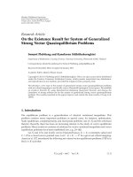
Figure 13: Performance of the proposed complexity-aware quantization.
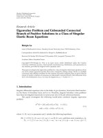
5. Simulation and Exper imental Results
5.1. Effectiveness of SCSAC. We first compare the proposed
SCSAC elimination with RAG-n [11], which stands for a
representative computation complexity minimization tech-
nique of FIR filters. The ideal coefficients are synthesized
using the Parks-McClellan’s algorithm [41] and represented
in the IEEE 754 double-precision floating-point format. The
passband and the stopband frequencies are at 0.4π and
0.6π, respectively. The coefficients are then quantized to the
nearest 12-bit fractional numbers, because the complexity of
the RAG-n algorithm is impractical for longer wordlengths
[11]. The proposed SCSAC elimination depends on the
coefficient representation, and therefore the 12-bit quantized
coefficients are first CSD-recoded. RAG-n always has fewer
additions than the
±2-bit SCSAC elimination as shown in
Tabl e 1. In order to have the information on implementation
complexity, full-precision and nonpipelined SDFG are t hen
constructed (see Section 4)fromthecoefficients after CSE.
The filters are synthesized using Synopsys Design Compiler
with the 0.35 μm CMOS cell library under a fairly loose 50-
ns cycle-time constraint and optimized for area only. The
area estimated in the equivalent gate count is shown beside
the required number of additions in Table 1.Thecombina-
tional and noncombinational parts are listed in parentheses,
respectively. Although RAG-n requires fewer additions, the
proposed SCSAC has smaller area complexity because RAG-
nappliesonlyonthetransposed-formFIRfilterswith
the MCM (multiple constant multiplications) structure,
which requires higher-precision intermediate variables and
increases the silicon area of both adders and registers. Note
we do not use bit-serialization when comparing our results
with RAG-n.
5.2. Comparison of Quantization Error and Hardware Com-
plexity. In order to demonstrate the “complexity awareness”
of the proposed framework, w e first synthesize the coeffi-
cients of a 20-tap linear-phase FIR filter using the Parks-
McClellan’s algorithm [41]. The filter’s pass and the stop
frequencies are 0.4π and 0.6π, respectively. These real-valued
coefficients are then quantized with various approximation
strategies. An optimal scaling factor is explored from 0.7 to
1.4 for a complete octave about
±3 dB gain tolerance during
the quantization. The search range is complete because
the quantization results repeat for a power-of-two factor.
Figure 13 displays the quantization results. The two dash
lines show the square errors versus the predefined addition
budgets without CSE for the 2’s complement (left) and
SPT (right; the Li’s method [28]) quantized coefficients. In
other words, these two dash lines represent the coefficients
quantized with pure successive approximation, in which
no complexity-aware allocation or CSE was applied. The
allocated nonzero terms are thus the given budget plus one.
For comparable responses, the nearest approximation with
SPT reduces 37.88%
∼ 43.14% budgets of the results of
approximation with 2’s complement coefficients. This saving
is even greater than the 29.1%
∼ 33.3% by performing
CSE on the 2’s complement coefficients, which is shown as
EURASIP Journal on Advances in Signal Processing 11
0000000 0000
000000000000
000000000000
000000100100
000000 0000
000000000000
000000000000
00010 000000
000000000000
000000000000
00 000100 00
000000000000
010000000000
100100000000
000000000000
000100000000
000010100000
000000101000
0000000 0000
000000000000
000000101000
000000100100
000000 0000
0000 0010100
000000000000
00010 000000
000010100000
000 00101000
00 000100 00
000000000000
010100 0 000
100100101000
h
0
h
1
h
2
h
3
h
4
h
5
h
6
h
7
h
8
h
9
h
10
h
11
h
12
h
13
h
0
h
1
h
2
h
3
h
4
h
5
h
6
h
7
h
8
h
9
h
10
h
11
h
12
h
13
−1−1
−1
−1 −1
−1
−1
−1
−1
−1
−1
−1
−1
−1
−1
−1
x
9
+ x
5
1
−(x
9
+ x
5
1) + x
12
x
8
+ x
2
2
(x
9
+ x
5
1 − x
12
)+x
13
Figure 14: Quantization result of a 28-tap low-pass FIR filter.
Table 2: Quantization error comparison.
SCSAC (±0) SCSAC (±2)
taps # CSD+CSE
∗
Proposed
∗
# CSD + CSE
∗
Proposed
∗
12 23 8.817235 2.727223 21 5.084159 2.727223
16 31 6.773190 3.696292 28 5.209612 3.835811
20 39 5.645929 4.975382 33 17.641685 15.349970
24 44 11.626458 20.547154 40 9.803638 17.781817
28 53 18.317564 8.483186 48 7.218225 20.590703
32 57 20.067199 15.768930 52 23.353057 17.632664
∗
square error in the unit of 10
−10
.
Table 3: Comparison of different quantization approaches.
Algorithm # tap w NPRM(dB) #SPT #ADD
Li et al. [28]2812−50.35 60 —
Chen and Willson [27]28 11
−50.12 60 40
Xu [29]2812
−50.05 62 32
Proposed
28 12
−50.21 66 38
28 10
−49.78 56 32
the solid line between [42]. CSE also saves the additions of
SPT coefficients, but with much less significant reduction. As
shown in the figure, the two curves almost go in parallel as
the budget decreases, which indicates that no more shared
subexpressions are extracted and eliminated [43]. Finally,
the rightmost three curves are results from our complexity-
aware quantization with the proposed SCSAC elimination.
Different amount of shift limits are applied to show that
SCSAC with
±2 shifts is enough. For comparable responses,
the pr oposed SCSAC saves 10.34%
∼ 19.51% budgets of the
SPT coefficients, while reducing 49.06%
∼ 50.94% budgets
of the 2’s complement case. Figure 13 clearly demonstrates
that the proposed q uantization framework can precisely
trade the complexity for quantization errors with the fine
stepping of a single addition.
Tabl e 2 summarizes the square errors of different
taps of FIR filters for demonstrating the performance of
the proposed approach. The coefficients are generated using
the Parks-McClellan’s algorithm with the same pass and
the stop frequencies. We first convert quantized results
(using straightforward quantization with 16 fractional bits)
into CSD representations and apply CSE to reduce t he
additions. An optimal scaling factor is applied on the
CSD coefficients for fair comparison. The second and the
fifth columns list the minimum number of additions of
all scaled coefficient sets with the
±0and±2SCSAC
elimination, respectively. These numbers are used as addition
budgets for our complexity-aware quantization algorithms.
The fourth and sixth columns show the quantization errors
of the proposed algorithm. As shown in the table, our
approach outperforms in most cases because of the direct
control over the additions and the zero-overhead SPT
allocation. Beside, the results show that approximation using
SPT coefficients has comparable coding performance with
CSD.
Tabl e 3 compares the quantization results of the pro-
posed framework and other methods. We first generate
the ideal coefficients for a 28-tap low-pass FIR filter using
Parks-McClellan’s algorithm. The stopband and passband
frequenciesaresetat0.3π and 0.5π, respectively. Besides, the
stopband and passband ripples have equal weightings. We
then quantize the ideal coefficient with 12-bit wordlength to
achieve
−50 dB normalized peak ripple magnitude (NPRM
[19]). The fifth column of Table 3 shows the number
of SPT terms in the quantized coefficients and the sixth
column shows the required additions after CSE being
applied. Note that the third column shows the wordlength
(w)ofthequantizedcoefficients. The proposed method
requires 38 additions to achieve
−50.21 dB NPRM. This is
because the proposed method tries to minimize the square
error (between the q uantized and ideal coefficients) but
not NPRM. In fact, modifying the proposed complexity-
aware allocation such that NPRM is minimized is possible
andshouldbeabletoimprovetheresults.However,itis
interesting to note that our method still can achieve
−49.78
NPRM (which is still comparable to other algorithms’
results) when only using 32 additions. Figure 14 shows this
12 EURASIP Journal on Advances in Signal Processing
0
4
8
12
16
20
42-tap
(bit-parallel) (bit-parallel)
42-tap
(bit-serial) (bit-serial)
62-tap 62-tap
Adder tree (computational elements)
P/S + S/P (delay-line registers)
Gate count (×1, 000)
Figure 15: Area reduction of bit-serialization.
quantization result (the left shows the quantized coefficients
and the right shows the coefficient matrix after CSE being
applied). Because of the symmetry of the coefficients, only
the first half coefficients are given. This complexity is smaller
than other works except [29]. Nevertheless, the method in
[29] only considers common subexpression pattern 101 and
101
. So, our method should be able to find better results for
high-order filters, in which the higher-weighting common
subexpression patterns are more likely to present. Besides,
the proposed method can accurately control the number
of addition in filters, so efficient and fine-grain tradeoff
between filters’ qualities and complexities is possible, just as
demonstrated in Figure 13.
5.3. Evaluation of Bit-Serialization. For less timing-critical
applications, the proposed bit-serialization by retiming can
effectively reduce the silicon area. We design a 42-tap
anda62-taplow-passFIRfilterandsynthesizetheirbit-
serial architectures, including P/S, the adder tree, and S/P
with saturation logic using Synopsys Design Compiler with
0.35 μm CMOS cell library. Figure 15 showstheareasof
the bit-serial and bit-parallel implementations for the 42-
tap and 62-tap filters. The bit-serialization mainly reduces
the adder tree’s area so the delay-line registers’ area changes
not much. Our results show that bit-serialization saves 58%
and 53% areas of the adder t rees, which turns into 35%
and 33% saving on the overall areas, for the 42-tap and
62-tap filter examples, respectively. Note that the bit-serial
implementations are retimed w ith adder depth five and the
synthesis timing constraint is 8ns. Ho wever, the filters may
need to be retimed w ith shorter adder depths to meet stricter
timing constraints. For example, we have to retime the bit-
serial filters with adder dept one for a 3 ns timing constraint.
6. Conclusions
This paper presents the complexity-aware quantization
framework of FIR filters. We adopt three techniques for
minimizing the FIR filters’ complexity, that is, signed-digit
coefficient encoding, optimal scaling factor exploration, and
common subexpression elimination ( CSE). The proposed
framework seamlessly integrates these three techniques with
the successive coefficient approximation approach such that
designers can explicitly control the number of additions of
FIR filters. The simulation result shows that our approach
provides a smooth tradeoff between the quantization errors
and filter complexities. Besides, we also propose an improved
common subexpression sharing for sparse coefficient matri-
ces to save more additions. The proposed quantization
framework saves 49.06%
∼ 50.94% additions of the quan-
tization results simply using 2’s complement coefficient for
comparable filter responses. Moreover, under the same con-
straints of required additions, our method has comparable
performance to the optimally scaled results using canonic
signed digits (CSD) encoding, which has the theoretically
minimum nonzero terms. By the way, it outperforms CSD
in most cases because of the direct control ov er the number
of additions and the insertion of zero-overhead terms.
For ar ea-efficient implementations, the proposed frame-
work incorporates a systematic algorithm to minimize the
wordlengths of the intermediate variables by pushing as
many shifts as possible toward the root of the adder tree
while still preventing overflow. The shorter wordlengths
either result in smaller adders and registers or reduce the
roundoff error in fixed-wordlength implementations. We
also describe the synthesis of bit-serial FIR filters by retiming
to further reduce the silicon area for less timing-critical
applications. The simulation r esult sho ws the area efficiency
of various adder depths u nder different timing constraints
and indicates that 32.99%
∼ 34.97% silicon areas can
be saved by bit-serialization. Note that although we only
discuss the hardwired implementations in this paper, the
proposed complexity-aware quantization algorithm can be
easily adapted to other implementation styles, such as the
multiplier-less FIR filters on programmable processors.
Acknowledgments
This research was supported by the National Science Council
under Grants NSC99-2220-E-009-057 and NSC99-2220-E-
009-0140. The authors would like to thank David Novo and
the anonymous reviewers for their helps on improving this
paper.
References
[1] A. V. Oppenheim, R. W. Schafer, and J. R. Buck, Discrete-
Time Signal Processing,PrenticeHall,NewYork,NY,USA,2nd
edition, 1999.
[2] Y. Voronenko and M. Püschel, “Multiplierless multiple con-
stant multiplication,” ACM Transactions on Algorithms,vol.3,
no. 2, Article ID 1240234, pp. 1–39, 2007.
[3]K.K.Parhi,VLSI Digital Signal Processing Systems—Design
and Implementation, John Wiley & Sons, New York, NY, USA,
1999.
[4]M.Potkonjak,M.B.Srivastava,andA.P.Chandrakasan,
“Multiple constant multiplications: efficient and versatile
framework and algorithms for exploring common subex-
pression elimination,” IEEE Transactions on Computer-Aided
Design, vol. 15, no. 2, pp. 151–165, 1996.
EURASIP Journal on Advances in Signal Processing 13
[5] R. I. Hartley, “Subexpression sharing in filters using canonic
signed digit multipliers,” IEEE Transactions on Circuits and
Systems II, vol. 43, no. 10, pp. 677–688, 1996.
[6]R.Pasko,P.Schaumont,V.Derudder,S.Vernalde,andD.
Durackova, “A new a lgor ithm for elimination of common
subexpressions,” IEEE Transactions on Computer-Aided Design,
vol. 18, no. 1, pp. 58–68, 1999.
[7] M. Martínez-Peiró, E. I. Boemo, and L. Wanhammar, “Design
of high-speed multiplierless filters using a nonrecursive signed
common subexpression algorithm,” IEEE Transactions on
Circuits and Systems II, vol. 49, no. 3, pp. 196–203, 2002.
[8]C.Y.Yao,H.H.Chen,T.F.Lin,C.J.Chien,andC.T.
Hsu, “A novel common-subexpression-elimination method
for synthesizing fixed-point FIR filters,” :IEEE Transactions on
Circuits and Systems I: Regular Papers, vol. 51, no. 11, pp. 2215–
2221, 2004.
[9] C.H.Chang,J.Chen,andA.P.Vinod,“Informationtheoretic
approach to complexity reduction of FIR filter design,” IEEE
Transactions on Circuits an d Systems I: Regular Papers, vol. 55,
no. 8, pp. 2310–2321, 2008.
[10] F. Xu, C. H. Chang, and C. C. Jong, “Contention resolution—a
new approach to versatile subexpressions sharing in multiple
constant multiplications,” IEEE Transactions on Circuits and
Systems I: Regular Papers, vol. 55, no. 2, pp. 559–571, 2008.
[11] A. G. Dempster and M. D. Macleod, “Use of minimum-adder
multiplier blocks in FIR digital filters,” IEEE Transactions on
Circuits and Systems II, vol. 42, no. 9, pp. 569–577, 1995.
[12] D. B. Bull and D. H. Horrocks, “Primitive operator digital
filters,” IEE Proceedings, Circuits, Devices and Systems, vol. 138,
no. 3, pp. 401–412, 1991.
[13] H. J. Kang, “FIR filter synthesis algorithms for minimizing the
delay and the number of adders,” IEEE Transactions on Circuits
and Systems II, vol. 48, no. 8, pp. 770–777, 2001.
[14] H.Choo,K.Muhammad,andK.Roy,“Complexityreduction
of digital filters using shift inclusive differential coefficients,”
IEEE Transactions on Signal Processing, vol. 52, no. 6, pp. 1760–
1772, 2004.
[15]Y.WangandK.Roy,“CSDC:anewcomplexityreduction
technique for multiplierless implementation of digital FIR
filters,” IEEE Transactions on Cir cuits and Systems I: Regular
Papers, vol. 52, no. 9, pp. 1845–1853, 2005.
[16] S. Ramprasad, N. R. Shanbhag, and I. N. Hajj, “Decorrelating
(DECOR) transformations for low-power digital filters,” IEEE
Transactions on Circuits and Systems II, vol. 46, no. 6, pp. 776–
788, 1999.
[17] T. S. Chang, Y. H. Chu, and C. W. Jen, “Low-power FIR
filter realization with differential coefficients and inputs,” IEEE
Transactions on Circuits and Systems II, vol. 47, no. 2, pp. 137–
145, 2000.
[18] A. P. Vinod, A. Singla, and C. H. Chang, “Low-power differ-
ential coefficients-based FIR filters u sing hardware-optimised
multipliers,” IET Circuits, Devices and Systems,vol.1,no.1,pp.
13–20, 2007.
[19] Y. C. Lim, “Design of discrete-coefficient-value linear phase
FIR filters with optimum normalized peak ripple magnitude,”
IEEE Transactions on Circuits and Systems, vol. 37, no. 12, pp.
1480–1486, 1990.
[20] O. Gustafsson and L. Wanhammar, “Design of linear-phase
FIR filters combining subexpression sharing with MILP,” in
Pr oceedings of the 45th Midwest Symposium on Circuits and
Systems, pp. III9–III12, August 2002.
[21] Y. J. Yu and Y. C. Lim, “Design of linear phase FIR filters
in subexpression space using mixed integer linear program-
ming,” IEEE Transactions on Circuits and Systems I: R egular
Papers, vol. 54, no. 10, pp. 2330–2338, 2007.
[22] J. Yli-Kaakinen and T. Saramäki, “A systematic algorithm
for the design of multiplierless FIR filters,” in Proceedings of
the IEEE International Symposium on Circuits and Systems
(ISCAS ’01), pp. 185–188, May 2001.
[23] M. Aktan, A. Yurdakul, and G. Dündar, “An algorithm for
the design of low-power hardware-efficient FIR filters,” IEEE
Transactions on Circuits an d Systems I: Regular Papers, vol. 55,
no. 6, pp. 1536–1545, 2008.
[24] R. Jain, G. Goossens, L. Claesen et al., “CAD tools for the
optimized design of VLSI wave digital filters,” in Proceedings
of the IEEE International Conference on Acoustics, Speech, and
Signal Processing (ICASSP ’85), pp. 1465–1468, Tampa, Fla,
USA, March 1985.
[25] H. Samueli, “Improved s earch algorithm for the design of
multiplierless FIR filters with powers-of-two coefficients,”
IEEE Transactions on Circuits and Systems, vol. 36, no. 7, pp.
1044–1047, 1989.
[26] D. A. Boudaoud and R. Cemes, “Modified sensitivity criterion
for the design of powers-of-two FIR filters,” Electronics Letters,
vol. 29, no. 16, pp. 1467–1469, 1993.
[27] C. L. Chen and A. N. Willson, “A trellis search algor ithm
for the design of FIR filters with signed-powers-of-two
coefficients,” IEEE Transactions on Circuits and Systems II:
Analog and Digital Signal Processing, vol. 46, no. 1, pp. 29–39,
1999.
[28]D.Li,Y.C.Lim,Y.Lian,andJ.Song,“Apolynomial-
time algorithm for designing FIR filters with power-of-two
coefficients,” IEEE Transactions on Signal Processing, vol. 50,
no. 8, pp. 1935–1941, 2002.
[29] F.Xu,C.H.Chang,andC.C.Jong,“Designoflow-complexity
FIR filters based on signed-powers-of-two coefficients with
reusable common subexpressions,” IEEE Transactions on
Computer-Aided Design, vol. 26, no. 10, pp. 1898–1907, 2007.
[30] M. Mehendale and S. D. Sherlekar, LSI Synthesis of
DSP Kernels—Algorithmic and Architectural Transformations,
Kluwer Academic, Boston, Mass, USA, 2001.
[31] Y. Jang and S. Yang, “Low-power CSD linear phase FIR filter
structure using vertical common sub-expression,” Electronics
Letters, vol. 38, no. 15, pp. 777–779, 2002.
[32] A. P. Vinod a nd E. M. K. Lai, “Low power and high-speed
implementation of FIR filters for software defined radio
receivers,” IEEE Transactions on Wireless Communications,vol.
5, no. 7, Article ID 1673078, pp. 1669–1675, 2006.
[33] P. B. Denyer and D. Renshaw, VLSI Signal Processing—A Bit-
Serial Approach, Addison-Wesley, Reading, Mass, USA, 1985.
[34] R. Jain, F. Catthoor, J. Vanhoof et al., “Custom design of a
VLSI PCM-FDM transmultiplexor from system specifications
to circuit layout using a computer aided design system,” IEEE
Transactions on Circuits and Systems, vol. 33, no. 2, pp. 183–
195, 1986.
[35] R. I. Hartley and J. R. Jasica, “Behavioral to structural
translation in a bit-serial silicon compiler,” IEEE Transactions
on Computer-Aided Design, vol. 7, no. 6, pp. 877–886, 1988.
[36] K. K. Parhi, “A systematic approach for design of digit-serial
signal processing architectures,” IEEE Transactions on Circuits
and Systems, vol. 38, no. 4, pp. 358–375, 1991.
[37] H. de Man, L. Claesen, J. van Ginderdeuren, and L. Darcis, “A
structured multiplier-free digital filter building block for LSI
implementation,” in Proceedings of the European Conference on
Circuit Theory and Design (ECCTD ’80), pp. 527–532, 1980.
14 EURASIP Journal on Advances in Signal Processing
[38] C. E. Leiserson and J. B. Saxe, “Retiming synchronous
circuitry,” Algorithmica, vol. 6, no. 1, pp. 5–35, 1991.
[39] L. Claesen, H. DeMan, and J. Vandewalle, “Delay management
algorithms for digital filter implementations,” in Proceedings
of the 6th European Conference on Circuit Theory and Design
(ECCTD ’83), pp. 479–482, 1983.
[40]T.H.Cormem,C.E.Leiserson,R.L.Rivest,andC.Stein,
Introduction to Algorithms, MIT Press, Cambridge, Mass, USA,
2nd edition, 2001.
[41] J. H. McClellan, T. W. Parks, and L. R. Rabiner, “A computer
program for designing optimum FIR linear phase digital
filters,” IEEE Transactions on A udio and Electroacoustics,vol.
21, no. 6, pp. 506–526, 1973.
[42] T. J. Lin, T. H. Yang, and C. W. Jen, “Area-effective FIR filter
design for multiplier-less implementation,” in Proceedings of
the IEEE International Symposium on Circuits and Systems
(ISCAS ’03), vol. 5, pp. V173–V176, 2003.
[43] T. J. Lin, T. H. Yang, and C. W. Jen, “Coefficient optimization
for area-effecti ve multiplier-less FIR filters,” in Proceedings of
the International Conference on Multimedia and Expo, pp. 125–
128, 2003.