Báo cáo hóa học: " Research Article Cross Layer PHY-MAC Protocol for Wireless Static and Mobile Ad Hoc Networks" pot
Bạn đang xem bản rút gọn của tài liệu. Xem và tải ngay bản đầy đủ của tài liệu tại đây (1.47 MB, 13 trang )
Hindawi Publishing Corporation
EURASIP Journal on Advances in Signal Processing
Volume 2009, Article ID 278041, 13 pages
doi:10.1155/2009/278041
Research Article
Cross Layer PHY-MAC Protocol for Wireless Static
and Mobile Ad Hoc Networks
Sylwia Romaszko and Chris Blondia
Interdisciplinary Institute for B roadband Technology, University of Antwerp, Middelheimlaan 1, 2020 Antwerp, Belgium
Correspondence should be addressed to Sylwia Romaszko,
Received 31 January 2008; Revised 5 June 2008; Accepted 26 July 2008
Recommended by S. Toumpis
Multihop mobile wireless networks have drawn a lot of attention in recent years thanks to their wide applicability in civil
and military environments. Since the existing IEEE 802.11 distributed coordination function (DCF) standard does not provide
satisfactory access to the wireless medium in multihop mobile networks, we have designed a cross-layer protocol, (CroSs-layer
noise aware power driven MAC (SNAPdMac)), which consists of two parts. The protocol first concentrates on the flexible
adjustment of the upper and lower bounds of the contention window (CW) to lower the number of collisions. In addition, it uses
a power control scheme, triggered by the medium access control (MAC) layer, to limit the waste of energy and also to decrease the
number of collisions. Thanks to a noticeable energy conservation and decrease of the number of collisions, it prolongs significantly
the lifetime of the network and delays the death of the first nodewhile increasing both the throughput performance and the sending
bit rate/throughput fairness among contending flows.
Copyright © 2009 S. Romaszko and C. Blondia. This is an open access article distributed under the Creative Commons Attribution
License, which permits unrestricted use, distribution, and reproduction in any medium, provided the original work is properly
cited.
1. Introduction and Problem Definition
The IEEE 802.11 [1], standard for wireless local area
networks (WLANs) specifies as contention-based MAC
mechanism the DCF, which is based on carrier sense
multiple access with collision avoidance (CSMA/CA). The
CSMA/CA mechanism assumes that each node uses a certain
fixed transmission power for each transmission and that
the network is homogeneous. However, nowadays wireless
nodes, such as laptops, personal digital assistants (PDAs),
and other handheld units, are usually equipped with batteries
that provide a limited amount of energy. Since the power
level determines the network topology, the battery life
extension (thus the lifetime of a node) is an important factor
in ad hoc networks. In a pure wireless multihop network,
nodes have a limited transmission range. Depending on
the number of active nodes, the density of the network
affects the energy consumption, because with an increasing
number of collisions and retransmissions, the expenditure of
energy increases as well. One well-known direction in order
to save energy and reuse the channel is by manipulating
the power (power saving/controlling) or the carrier sense
threshold. Another direction is focused on enhancements of
the IEEE 802.11 MAC since the existing standard does not
meet multihop mobile ad hoc network expectations. The
weaknesses and unfairness of the binary back-off algorithm
(BEB) of the IEEE 802.11 DCF and contention window
resetting scheme used by this standard is the reason to
improve/change the back-off mechanism and resetting CW
algorithm.
The observation of these two problems led to the design
of a novel cross-layer protocol, SNAPdMac. On one hand,
our protocol employs tuning of the transmit power based on
the level of noise and the collision ratio on the MAC level.
On the other hand, it tackles the weaknesses and unfairness
of the IEEE 802.11 MAC layer by tuning the lower and upper
bounds of the contention window range and employing a
different resetting strategy.
The remainder of the paper is organized as follows.
The next section presents the IEEE 802.11 DCF standard
and points out its problems. In Section 3, the related work
is presented. In Section 4, the proposed MAC protocol is
described. Section 5 describes the metrics and parameters
used in the simulations and sets the goals in this work,
2 EURASIP Journal on Advances in Signal Processing
and Section 6 shows the performance evaluation of the
proposed protocol against the IEEE 802.11 DCF and the basic
power control protocol [2]. Finally, concluding remarks are
formulated in Section 7.
2. IEEE 802.11 Standard
The IEEE 802.11 standard specifies two medium access
control mechanisms of which only the DCF is relevant to ad
hoc operation. The DCF specifies that a node needs to sense
the medium before transmitting. If the medium is idle, the
node waits for a random deferral time before transmitting.
This back-off time is a random value multiplied by the slot
time, where the random value is a pseudorandom integer,
picked from the [0,CW] range. In each slot where the
medium is sensed idle, the back-off counter is decremented
until it reaches zero. When the counter reaches zero, the
node starts its transmission. If during back-off the medium
is sensed busy, the back-off counter is frozen during the
ongoing transmission and decrements again as soon as the
medium is sensed idle.
When a transmission fails, that is, no acknowledgment is
received, the DCF specifies that the CW needs to be doubled
according to the BEB algorithm, up to a maximum back-off
size, the maximum value of CW (CW
max
). When the packet
is not transmitted successfully after a maximum number of
retransmissions, the packet is dropped. Upon a successful
transmission or when a packet has been dropped, the CW
is reset to the static minimum CW
DCF
min
value.
This approach of resolving collisions is not only unfair
but also inefficient. Although the CW is doubled upon a
retransmission, there is always a probability that contending
nodes randomly choose the same contention slot, especially
when the number of active nodes increases. On the other
hand, receiving a packet successfully does not mean that
the contention level has been dropped. Furthermore, the
minimum and maximum CW sizes (where CW
min
≤
CW ≤ CW
max
) are fixed in the IEEE 802.11 DCF standard
independently of the network load and channel conditions.
3. Related Work
Many approaches have already been proposed to reduce the
number of collisions by substituting the binary exponential
back-off algorithm of the IEEE 802.11 by novel back-off
approaches or selecting an intermediate value instead of
resetting the CW value to its initial value. Several papers
focus on changing the lower and upper bounds of the
CW interval [3–5] but usually with different goals, such
as the mitigation of selfish MAC misbehavior ([4]) or the
reduction of the latency for event-driven wireless sensor
networks (WSNs) ([3]). The most related work to our
back-off mechanism is the determinist contention window
algorithm (DCWA) in [5]. DCWA increases the upper and
lower bounds instead of just doubling the CW value. In
each contention stage, a station draws a back-off interval
from a distinct back-off range that does not overlap with
the other back-off ranges associated to the other contention
stages. In addition, the back-off rangeisreadjustedupon
each successful transmission by taking into account the
current network load and history (resetting the back-off ranges
mechanism; see details in [5]).
Among the related work concerning energy conservation,
such as power saving or power control mechanisms, the
power saving mechanism (PSM) is the most familiar. It is
provided by the standard [1], which allows a node to go
into doze mode. Power control schemes, varying the transmit
power in order to reduce the energy consumption, have
already been presented in many studies; for example, see
[2, 6–10]. These schemes and many others have shown
that power control protocols can achieve a better power
conservation and higher system throughput through a better
spatial reuse of the spectrum.
Antagonists of power control approaches argue that
adjusting/changing the power level introduces asymmetric
links while the carrier sense (CS) range is always symmetric.
However, in a real world both asymmetric links and asym-
metric CS ranges exist [11]. That is why there is a plenty
of work in this field focusing not only on power saving or
power control, but also on spatial reuse that employs the
IEEE 802.11 physical carrier sensing.
One part of the research in this field focuses on
dependencies and tradeoffs between both the transmit power
and the carrier sense threshold [12, 13], while another part
focuses only on the adjustment of the carrier sense threshold
[14–16]. The work in [12] investigated the tuning of the
transmit power, carrier sense threshold, and data rate in
order to improve spatial reuse. The authors have shown that
tuning the transmit power is more advantageous than tuning
the carrier sense threshold.
Cross-layer protocols contributing to the enhancement
of the MAC layer and the adjustment of the power level
have also been presented in many papers. One of them, the
power adaptation for starvation avoidance (PASA) algorithm
[17], was designed following the observation from [10]
that the request-to-send/clear-to-send (RTS/CTS) collision
avoidance mechanism of the IEEE 802.11 DCF cannot
eliminate collisions completely. This can lead to a channel
capture where a channel is monopolized by a single or a
few nodes. The authors of [17
] studied how to control
the transmission power properly in order to offer a better
fairness and throughput by avoiding a channel capture. The
power level increases exponentially and decreases linearly in
the PASA, while using an RTS/CTS control scheme. PASA is
not applicable with the basic access scheme. It requires that
a neighbor power table (NPT) is maintained by each node
with information such as the minimum power that must
be maintained according to the distance to the destinations,
which should be obtained through some location service.
PASA achieves a better Jain’s fairness index, however it
suffers from a degradation of the throughput, which is
noticeable in mobile ad hoc scenarios. After all, maintaining
the NPT table with “fresh” data is not realistic in a mobile
ad hoc environment taking into account interferences, fading
effects, movement of the nodes, and deaths and new entriers
of nodes.
The carrier sense multiple access protocol with power
back-off (CSMA/PB) has been presented in [18]. The
EURASIP Journal on Advances in Signal Processing 3
CSMA/PB reduces the transmission power level in order
to avoid collisions, following the observation that, in a
smaller transmission area, interferences and contentions are
expected to be reduced. Results obtained in [18] are based on
an optimistic centralized power-aware routing strategy which
illustrates the potential of the power back-off. The CSMA/PB
protocol has been evaluated with three transmission power
levels only, thus the amount of power decreases fast.
Therefore, it is really important that the routing protocol
takes power levels into account. Each node has to maintain
the routing table with entries for each destination with
corresponding power levels.
4. Proposed Protocol
The goal of the SNAPdMac protocol is to save energy (which
leads to an extension of the lifetime of nodes) and to reduce
the number of collisions. However, the SNAPdMac protocol
does not degrade the throughput performance and fairness
in terms of the throughput and sending rate, while fulfilling
these goals.
TheSNAPdMacprotocoltacklesacoupleofproblems
that exist in the current implementation of the standard. It
does this by two means, first it concentrates on the flexible
adjustment of the upper and lower bounds of the CW to
lower the number of collisions. Secondly, it uses a power
control scheme to limit the waste of energy and also to lower
the number of collisions. Hence, it has a MAC-PHY cross-
layer architecture.
To tackle the inefficient use of the back-off window in
the standard, we developed a MAC protocol that makes use
of our prior work (Enhanced selection Bounds algorithm
(EsB) [19]) during the recovery stage. The EsB adjusts the
lower and upper bounds of the CW range, taking into
account the number of retransmissions attempts, the 1-
hop active neighbors, and the remaining battery level. Each
node can estimate how many neighbors it has in its 1-
hop neighborhood, based on successfully detected signals or
using the table that is built by a routing mechanism. In [20]
the utilization rate of the slots (slot utilization)observedon
the channel by each station is used for a simple, effective
and low-cost load estimate of the channel congestion level.
During the resetting stage, the CW value is reset to a value
which depends on the history of collisions. This forms the
MAC part of the SNAPdMac protocol and results in a
reduction of the number of collisions.
The goal is not only to lower the number of collisions, but
also to save energy. If we reflect on the reason why messages
collide, it becomes clear that this is because too many nodes
are too close to each other. They could be positioned a few
meters from each other, but their transmission range is far
greater than these few meters. Hence, the nodes are too close
to each other relative to their respective transmission range.
This not only results in a higher number of collisions, but
also in an excessive use of energy to transmit a packet.
The SNAPdMac power control part is based on this
observation and it lowers its transmission power (while
observing too high noise in the vicinity) when it does not
get the acknowledgment that a packet has been received
successfully. The final result will be that all nodes will find
their optimal transmission power that ensures that they can
reach their neighbors, but not interfere with other nodes.
However, not receiving an acknowledgment for a sent
packet does not always mean that the packet was lost or
corrupted because there was too much interference. It could
also happen that the transmission power was simply too
low to reach any of the surrounding nodes. Therefore, the
SNAPdMac protocol takes the signal-to-interference-and-
noise ratio (SINR) into account. If no acknowledgment has
been received, but the noise level (deducted from the SINR)
is low, then we assume that the transmission power was
too low to reach any of the neighbors. In that case the
transmission power is increased.
The signal to interference and noise ratio,
SINR
=
Power
RX
Noise + Interferences
,(1)
is an important metric of the wireless communication link
quality. A radio signal can be correctly decoded by the
intended receiver only if the ratio between the sender power
(Power
RX
) of the actual signal to be received and the
sum of all power levels experienced due to other signals
(Interferences) currently transmitted plus an ambient noise
power level (Noise) is above a certain hardware-dependant
threshold β (minimum signal-to-interference ratio required
to successfully receive a message):
SINR
≥ β. (2)
The higher the SINR, the higher the rate that packets can be
transmitted reliably. Depending on the modulation scheme,
different threshold values β are valid.
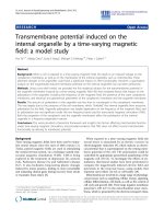
Figure 1 shows a detailed diagram describing how the
SNAPdMac protocol works. In the figure, the PHY layer has
been placed in a dashed area. Note that the protocol considers
three main cases for each transmission:
(a) recovery mechanism, the number of retransmission
attempts is larger than 0 and lower than the thresh-
old,
(b) dropped packet, the number of retransmission
attempts exceeds the threshold,
(c) CW resetting upon a successful reception.
4.1. Recovery Mechanism. When a packet has to be retrans-
mitted but the number of retransmission attempts does
not exceed the limit, the recover y mechanism is processed.
The recovery mechanism makes use of the EsB algorithm
from our prior work [19]. EsB is focused on adjusting the
lower and upper bounds of the CW interval, considering
the number of retransmission attempts (nr
AT T
), the number
of 1-hop active neighbors (NrN), and the coefficient of
remaining energy (coe
RE
).
According to the EsB algorithm, upon each retransmis-
sion, a node doubles its CW size first (as in [1]) and then
the CW bounds are adjusted by the EsB mechanism. The
4 EURASIP Journal on Advances in Signal Processing
Packet
received
No collision
CW
×2
CW
= CW
min
Ye s
RatioColl
> threshold
No
Packet
dropped
CW
= CW
max
RatioColl
> threshold
No
Ye s
Ye s
Power TR
PHY
Power TR
×2
Collision
& try again
CW
EsB with
lower B
= 0
Power TR
PHY
Power TR
No
Ye s
CW
EsB
To o m u c h
noise
MAC
Collision
Transmission
Ye s
Tr ie s > max
No
Retransmission
No
Figure 1: Diagram of the SNAPdMac protocol.
-Upon first transmission-
lB
0
= lB
DCF
= 0; uB
0
= CW
min
= CW
DCF
min
;
-Upon each retransmission-
(1) IB
tmp
=
uB
i
−1
2
+ NrN + nr
ATT
∗
log
10
(nr
ATT
+ γ)
(2) lB
i
= lB
tmp
∗coe
RE
;
where a constant γ
= 3.0;
(3) uB
i
= (2 ∗uB
i−1
) ∗log
10
(NrN ∗coe
RE
+ nr
ATT
+ γ)
where γ
= 3.0 if NrN < 2, and 0 otherwise;
(4) IF (uB
i
> CW
max
) then uB
i
= CW
max
,
where CW
max
= CW
DCF
max
+CW
DCF
min
;
Algorithm 1: EsB algorithm.
back-off timer is randomly selected from the range delimited
by the lower bound (lB) and upper bound (uB): back off
timer
= random [lB
i
, uB
i
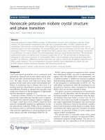
]. Figure 2 depicts an example of a
possible selection of the lower and upper bounds in the EsB
algorithm. In this case, we consider the prior (T
i−1
), current
(T
i
), and future (T
i+1
) state. In the prior (T
i−1
) state, the
lower bound is a bit lower than CW
DCF
(128) and the upper
bound a bit lower than 256 (next chosen upper bound by
the BEB algorithm of the IEEE 802.11 DCF standard). In
the current state, these values are increased but they can be
lower or larger than consecutive BEB values as depicted in
the figure. We also let a node exceed the CW
DCF
max
value, but
not more than the number of CW
DCF
min
slots. The algorithm of
the EsB scheme is shown in Algorithm 1.
The lB
i
is dependent on the uB
i−1
/2 value and the
logarithmic function (line 1) in order to ensure that this
bound does not increase too fast. First, the use of uB
i−1
/2
prevents choosing too high values of the lower bound, in
particular if the NrN and nr
AT T
are not (so) high.
Secondly, the logarithmic function takes care of the slight
increase of the lower bound. The γ is chosen in such a way
that the result of the logarithmic function is higher than 1/2,
lB
i−1
lB
i
lB
i+1
uB
i−1
uB
i
uB
i+1
T
i−1
T
i
T
i+1
128 256 512 1024
CW
DCF
min
Initial-previous values of lB, uB
Consecutive possible values of lB, uB
BEB values of 802.11 DFC
Figure 2: Bounds selection of EsB algorithm.
hence the lower bound will be reasonably higher relative to
the previous selected one. Thus, if a node has only a few
active neighbors, the lB
i
value will be small. If a node resides
inadensenetworkwithmanyactivenodes,thisisreflected
in a larger value of the lB
i
, apart from the current nr
AT T
.
We also let each node shrink or extend the upper bound
(uB
i
) relative to the uB
DCF
i
.TheuB
i
is logarithmically
dependent on the NrN and nr
AT T
. In this way we obtain a
slight change (an increase or decrease) of the uB
i
compared
to the uB
i
achieved by [1]. An upper bound of the CW
interval should not increase too fast, because of unnecessary
deferring of contending nodes.
We also noticed that the adjustment of the lower and
upper bounds outperformed the IEEE 802.11 DCF, but that
both suffered from an unequal energy distribution. Some
nodes still had a lot of remaining energy when the first node
had already died. To solve this, we introduced the coefficient
EURASIP Journal on Advances in Signal Processing 5
Energy level (%)
100 85 70 55 40 25
Coefficient of energy (coe
RE
)
0.5
0.55
0.6
0.65
0.7
0.75
0.8
0.85
0.9
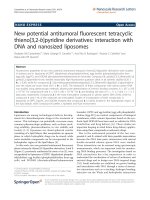
Figure 3: Change of coe
RE
.
(1) Pt
DIFF
= ε∗log
10
NrN
CURRENT
NrN
DESIRED
∗
Pt
TR−1
;
where ε
=
1
NrN
DESIRED
—is a constant
-recovery mechanism-
(2a) IF (SINR
CURRENT
> SINR
THRESHOLD
)
(3a) Pt
TR
= Pt
TR−1
+(ζ −1)∗Pt
DIFF
;
(4a) ELSE
(5a) Pt
TR
= Pt
MAX
−(ζ)∗Pt
DIFF
;
Algorithm 2: Enhanced power control.
of remaining energy (coe
RE
) in the algorithm. Depending
on the energy level of the battery, the coe
RE
value varies
(Figure 3). Notice that the value of coe
RE
logarithmically
increases, when the energy level decreases. We allow the
upper bound of the CW to decrease slightly depending on
the energy level. If a node has its maximum energy level,
it needs to wait a shorter time compared to a node with a
lower battery level, if both nodes have recognized the same
NrN and have an equal nr
AT T
. The upper bound increases
with a decreasing battery energy level. Thus, nodes with a
lower battery level wait longer in order to avoid a potential
collision.
As opposed to [5], a selected back-off interval
i
from
back-off stage
i
by a given node may overlap with a selected
back-off interval
i−1
from back-off stage
i−1
ofthisnodein
the EsB mechanism. This way the algorithm is less prone
to unnecessary loss of free slots both in sparse and dense
networks (when many neighbors are occasionally active).
The recovery mechanism of SNAPdMac is not limited
to the use of EsB only, it also employs our novel enhanced
power control of which the pseudocode of the recovery part is
presented in Algorithm 2.
The recovery part of the enhanced power control is based
on the noise level in the neighborhood. The amount of
noise in the vicinity, which is measured by assessing the
current SINR value, determines whether the power level
should increase or decrease. If the noise level is too low (the
current SINR, SINR
CURRENT
, is higher than the threshold
SINR
THRESHOLD
), the power level increases. Otherwise, the
power level decreases. The amount of increase and decrease
of the power is determined by the number of 1-hop active
neighbors (NrN
CURRENT
) and the previous transmit power
(Pt
TR
). Pt
MAX
is the maximum transmission power.
We have assumed that the desired number of neighbors
NrN
DESIRED
is fixed and set to 3, because at least 3 nodes
provide a completely connected network. The speed of the
decrease or increase can be adjusted by the variable ζ (2 or 3
in simulations), but a decrease of the power is always faster
than an increase.
During the recovery mechanism of SNAPdMac, the EsB is
used unchanged to adjust the CW range when the noise level
of the neighborhood is high. The presence of a lot of noise is
an indication that a lot of nodes are in the vicinity. To lower
the possibility of another collision even more, SNAPdMac
also decreases its transmission power as described in the
enhanced power control. By decreasing the power, a node gives
opportunity to other nodes to access the wireless channel,
which leads to the enhancement of the fairness between
nodes.
When, on the other hand, the noise level is low in the
neighborhood, only the upper bound of the CW range is
adjusted according to the EsB, whereas the lower bound is
kept at 0. Low noise level means that there is not so much
traffic in the air, and a node has more chance to access the
wireless medium compared to a node which happens to be
in a high contention area. Even more, if a retransmission
occurs but the noise level is low, a collision is not necessarily
the reason of the failed transmission. There exists a high
probability that the transmission of the packet failed, because
no receiver was in the range, or because of fading effects,
mobility, and so on. This is why we increase the power level
to extend the transmission range when the noise level is low
during the recovery mechanism.
4.2. Dropped Packet. Apacketisdropped when the number of
retransmission tries (Tries in Figure 1) exceeds the threshold
MAX. Upon this event, the CW value is not reset to its
minimum value as in the IEEE 802.11 DCF, but it maintains
its value of CW
max
. Since the packet has been retransmitted
a maximum number of attempts with different power levels
(upon each retransmission), the probability that a next
packet will be sent successfully is very low, therefore resetting
the CW to the minimum is pointless.
Although the CW value does not change when a packet
has been dropped, the power level decreases, in order to
lower the possibility of collisions. The pseudocode of the
dropped part of the enhanced power control algorithm is
presented above in Algorithm 3, which shows that the power
always decreases when a packet is dropped, because the
packet is abandoned anyway.
Unlike in the recovery part of the enhanced power control
algorithm, the dropped packet part is independent of the
6 EURASIP Journal on Advances in Signal Processing
(1) Pt
DIFF
= ε∗log
10
NrN
CURRENT
NrN
DESIRED
∗
Pt
TR−1
;
where ε
=
1
NrN
DESIRED
is a constant
-dropped packet-
(2b) IF (Drop and RatioColl > RatioColl
THR
)
(3b) Pt
TR
= Pt
MAX
−(ζ +1)∗Pt
DIFF
;
(4b) ELSE
(5b) Pt
TR
= Pt
MAX
−(ζ)∗Pt
DIFF
;
Algorithm 3: Enhanced power control.
current level of SINR. The amount of decrease of the power
is determined, like in the recovery part, by the number
of 1-hop active neighbors (NrN
CURRENT
) and the previous
transmit power (Pt
TR
). However, the history of the collision
ratio also affects the speed of the decrease of the power.
The history, RatioColl, is taken into account by means of an
exponential weighted mean average (EWMA) with respect to
past measurements, as shown in the following equation:
RatioColl
= χ ∗RatioColl
i−1
+(1− χ) ∗RatioColl
i
,(3)
where
RatioColl
i
=
Counter
Packet
SENT
−Counter
Packet
ACK
Counter
Packet
SENT
. (4)
The Counter
Packet
SENT
increases each time by one upon a first
transmission of a packet (this counter does not increase upon
retransmission attempts) and the Counter
Packet
ACK
increases by
one upon a successful reception of the acknowledgment
(ACK) of the transmitted (SENT) packet. Depending on the
RatioColl, the power decrease is normal or faster (faster
= 2
∗ normal). In static environments, the history plays a more
important role than in mobile environments. Therefore, we
allow the tuning of the χ value, which represents the amount
of importance history has. In static networks the χ is set to a
value larger than 0.5. On the other hand, in mobile networks,
where the history is less important because of the nodes
movement and fast changing instantaneous conditions, the
χ value is set to a value lower than 0.5.
Based on our extensive simulations, we have noticed that
an appropriate transmission power level is really important
since, if the rate of decrease/increase is too fast or too slow,
the protocol can be either too conservative or too aggressive.
Thanks to the possibility of tuning the variables ζ (speed
of the change of the power level) and/or RatioColl
THR
, the
connectivity of the network can be adjusted which leads to
a significant improvement of the throughput and lifetime
performance.
4.3. CW Resetting. Upon the successful reception of a packet,
the CW value is reset depending on the history of the
collision ratio. The CW value is reset based on whether
the value of RatioColl (3) is larger than the threshold,
RatioColl
THR
, or not. If the value of RatioColl is larger
than the threshold, the CW is decreased exponentially.
Otherwise, the CW value is reset to the initial minimum
value, which equals the initial minimum CW value of the
DCF mechanism.
5. Simulation Environment
5.1. Metrics and Parameters. The proposed cross-layer proto-
col has been implemented in the ns-2.29 network simulator
[21]. The simulations have been carried out for various
topologies, scenarios with different kinds of traffic, and
routing protocols. The following performance metrics have
been used:
(i) total packets received,
(ii) average throughput (Mbps),
(iii) lifetime LND (seconds),
(iv) FND: first active node died (seconds),
(v) lifetime RCVD (seconds),
(vi) sending bit rate Jain’s fairness
0 1,
(vii) throughput Jain’s fairness
0 1,
(viii) average aggregate delay (seconds),
(ix) κ-coefficient of collisions.
The first node died metric is defined as the instant in time
when the active (a node transmitting/receiving) first node
died. We have defined the network lifetime as the time
duration from the beginning of the simulation until the
instant when the active (a node transmitting/receiving) last
node died, that is, there is no live transmitter-receiver pair left
in the network. The Lifetime RCVD is specified as the instant
in time when the last packet is received.
The average throughput has been defined as
Thr
=
Total number
Packets
received
Simulation Time
[Mbps] (5)
and average sending bit rate has been defined as
Sbit
=
Total number
Packets
sent
Simulation Time
[Mbps]. (6)
The sending bit rate or throughput Jain’s fairness index is
estimated according to the following equation:
f (x)
=
(
n
i=1
α
i
)
2
n(
n
i=1
α
2
i
)
where α
i
≥ 0, (7)
where n is the number the contending flows, and α is sending
bit rate (Sbit) or throughput (Thr). If all flows get the same
amount of α (sending bit rate or throughput), then the
fairness index equals 1, thus the network is 100% fair [22].
Since the SNAPdMac protocol lives longer than the IEEE
802.11 DCF, we have defined a coefficient of collisions, κ,
which equals
TotalCollision
Total number
Packets
received
,(8)
EURASIP Journal on Advances in Signal Processing 7
Table 1: Simulations parameters.
Parameter Values
Number of active nodes 25, 50 (default)
Simulations area
≤ 1500 ×1500m
Topology Random
PHY/MAC DSSS, IEEE 802.11a
SINR thr. (dB) 24.05
Type of netwok homo/hetero-geneous
Initial energy (J) variable
= 0.5– ,5,20
Pt
MAX
−250 m 0.281838 W
Pt
MAX
−100 m 0.007214 W
txPower
init
250 100 meters
rxPower 45% of Pt
MAX
idlePower 30% of Pt
MAX
Capture Thr.(dB) 10
Tr affic model CBR/UDP
Payload size (bytes) 2048
100–8192
CW
min
−CW
max
(slots) 15–1023
RatioColl
THR
(%) 25–50, 50 (default)
χ (mobile
static) (0.1, 0.3 (default) 0.6, 0.8)
NrN
DESIRED
3
ζ 2(default)
3
Simulation time (s)
≤ 350
Routing AODV (default),DSR,OLSR
Movement random and constant
Mobility model Random Waypoint Model
Speed (m/s) 0
−2≤20; 1.5 − (default)
Access scheme Basic (default)
RTS/CTS
Table 2: Typical values of path loss exponent and shadowing
deviation.
Environment ρ (dB) σ (dB)
Outdoor
Free space
24to12
Outdoor
Shadowed Urban
2.7to5 4to12
Indoor
Line-of-sight
1.6to1.8 3to6
Indoor
Obstructed
4to6 6.8
inordertobeabletocomparefairlythetotalnumberof
collisions experienced with respect to the total number of
packets received.
In Ta bl e 1 we present the general simulation parameters,
where the abbreviation thr. means a threshold. Other
parameters used in specific simulations are mentioned in the
corresponding paragraphs. If we do not mention parameters
in some paragraphs, then the default values (in italic in
brackets shown in the table) are used.
In all simulations we have applied the shadowing prop-
agation model [21]withdifferent values of the path loss
exponent (ρ) and shadowing deviation (σ), according to the
Ta bl e 2 (see details in [21]).
We have assumed that the receive power (rxPower)is
approximately 45% (like in [23]) of the maximum transmit
power (Pt
MAX
).Theidlepower(idlePower) is approximately
30% of the maximum transmit power (Pt
MAX
), since in
reality the interface has a very large idle energy consumption
when it operates in ad hoc mode,asreportedin[24]. The
maximum transmit power of a node is assumed to cover
the whole transmission range of 100 meters (or 250 meters,
resp.). When the node energy level goes down to 0, a node
dies out.
In order to avoid the hidden and exposed node problems
in a wireless medium, the CSMA/CA protocol is extended
with a virtual carrier sensing mechanism, namely, RTS and
CTS control packets. We have executed simulations with
both the basic access and RTS/CTS schemes, however, we
have also observed that the usefulness of the RTS/CTS
exchange (especially in an ad hoc mobile environment) is
under discussion as already reported in [25–28].
5.2. Set Goals. In the simulations presented in the next sec-
tion, we have investigated the performance of the SNAPdMac
protocol against the IEEE 802.11 DCF standard and/or the
basic power control protocol from [2] (see in the appendix
a short description of the protocol). The IEEE 802.11 DCF
standard is later referred to as standard or STD in the text or
figures. We have defined three different scenarios:
(1) random static/mobile network with optimistic traffic,
(2) high density and contention (HD/C) homogeneous
network with a sudden change of contention level,
(3) high density and contention (HD/C) heterogeneous
network with a sudden change of contention level.
The goals of the first scenario are the following:
(i) verification whether the SNAPdMac protocol
decreases both the total number of collisions and the
number of collision per node in a static network as
expected,
(ii) the same verification as above but in mobile condi-
tions,
(iii) tuning RatioColl
THR
in order to find the best thresh-
old in static and mobile conditions,
(iv) verification of the importance of the transmission
failure history by tuning the χ value.
The goal of the second scenario is the investigation of the
behavior of the considered protocols in a mobile homoge-
neous ad hoc network with smooth and then sudden, sharp
increase of the contention level followed by a sudden, sharp
decrease of the network load.
The third scenario is focused on
(i) analysis of the behavior of considered approaches
in heterogeneous networks with basic and RTS/CTS
exchange scheme,
(ii) tuning the ζ in order to investigate whether a faster
(or slower) power increase/decrease has an influence
on the results obtained by the SNAPdMac protocol.
8 EURASIP Journal on Advances in Signal Processing
Node id number
0 5 10 15 20 25 30 35 40 45 50
Number of collisions
0
400
800
1200
1600
2000
2400
2800
3200
3600
“STD”
“SNAPdMac”
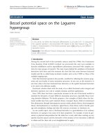
Shadowed urban area, 50 static nodes
Figure 4: Number of collisions per node; static network.
6. Simulations and Results
6.1. Random Network with Optimistic Traffic
6.1.1. Static Environment. First, we defined a simulation
scenario with 50 static nodes randomly distributed in a
shadowed urban area where nodes send a CBR packet (2048
bytes payload size) from the beginning till the end of the
simulation every 0.025 seconds. Figure 4 depicts the number
of collisions per node in one of the simulation scenario
runs (10 simulation runs in total). Notice that with the
SNAPdMac protocol most of the nodes have much fewer
collisions, although the lifetime of the network is increased
significantly (See Figure 6). Figure 5 shows the total number
of packets received by the DCF standard, basic power
control protocol, and SNAPdMac protocol. The tuning of the
SNAPdMac protocol has been investigated as can be observed
in the figure. The SNAPdMac
Coll25 and SNAPdMac Coll35
represent SNAPdMac with RatioColl
THR
equal to 25% and
35%, respectively. The SNAPdMac
08Coll35 has a χ value set
to 0.8 instead of 0.6. Independently of the adjusted values of
SNAPdMac, the protocol outperforms the IEEE 802.11 DCF
standard and basic power control protocol noticeably. The
SNAPdMac
08Coll35 achieves the best performance, which
means that the history of collisions experienced has an
influence in a static environment.
Figure 6 shows the gain in percentage over the IEEE
802.11 DCF standard obtained by the basic power control
protocol in the static network and the SNAPdMac protocol
in both static and mobile networks. Note that, thanks to PHY
(power level adjustment) and MAC (recovery mechanism
and CW resetting) layer treatment, the number of collisions
can be decreased noticeably while saving lot of the energy
which leads to an increase of the lifetimes (LND and
lifetime RCVD) of the network and the throughput. The
performance of the Lifetime RCVD is worse than the
performance of the lifetime of the network, which means that
some last transmitter-receiver pairs still have connections;
however, the packets cannot be routed to the destination. The
Shadowed urban area, 50 static nodes
Time (s)
0 5 10 15 20 25 30 35 40 45 50
Total packets received
0
3
6
9
12
15
18
21
×10
3
SNAPdMac 08Coll35
SNAPdMac
Coll35
SNAPdMac
Coll25
PSc
basic
STD
Figure 5: Total number of packets received versus time; static
network.
Packets
RCVD
κ
FND
Lifetime
Lifetime
RCVD
Sbit
fairness
Thr
fairness
Delay
Gain over DCF 802.11 (%)
−20
35
90
145
200
255
310
Power basic-static
SNAPdMac-static
SNAPdMac-mobile
Figure 6: General results, 50 static and mobile nodes.
performance of the throughput fairness, which is improved
tremendously, is explainable since nodes give others more
opportunity to access a wireless channel while decreasing the
transmit power level. On the other hand, by increasing the
power (upon a consecutive collision and too low noise in the
vicinity), their chance to get to the channel is increased since
their coverage transmit area is wider. However, the average
delay is degraded, because the SNAPdMac protocol adjusts
both the lower and upper bounds of the CW range and allows
to decrease (apart from an increase) the power level, which in
consequence can increase the average delay.
6.1.2. Mobile Environment. We have also executed simula-
tions in a mobile environment (with the maximum speed of
nodes 0.5, 1.0, and 1.5 m/s, resp.) with the same simulation
settings as above but this time with 20 simulation runs
in order to ensure the validity of our results. Figure 7
shows the total number of packets received by the IEEE
EURASIP Journal on Advances in Signal Processing 9
Shadowed urban area, 50 mobile nodes-max speed 1 m/s
Time (s)
0 5 10 15 20 25 30 35 40 45 50
Total packets received
0
2
4
6
8
10
12
14
16
18
20
×10
3
SNAPdMac 01Coll50
SNAPdMac
03Coll45
SNAPdMac
03Coll50
PSc
basic
STD
Figure 7: Total number of packets received; mobile network.
802.11 DCF standard, the basic power control protocol and
tuned SNAPdMac. In this simulation the RatioColl
THR
has
been set to 50% and 45% since the amount of collisions
in mobile networks is expected to be larger than in a
static environment. The χ value has been set to 0.3and
0.1 since in mobile conditions the history of collisions is
less important, because conditions change fast with the
movement of nodes. However, the history should be anyway
taken into account, and, as we have seen in our simulations,
the χ value should not be too low. Notice that the SNAPdMac
protocol with χ
= 0.1(SNAPdMac 01Coll50)performs
best till around 37 seconds; however, later it performs
worse than the SNAPdMac protocol with the χ equal to
0.3(SNAPdMac
03Coll50), achieving a worse throughput
and lifetime performance. Notice that it is better to set the
RatioColl
THR
to 50% than to a lower value in order to obtain
the best throughput performance.
Analyzing the general results depicted in Figure 6 we
can see that despite the mobile conditions, the SNAPdMac
protocol still outperforms the IEEE 802.11 DCF standard
noticeably in terms of the coefficient of collisions (κ),
throughput, (receiving) lifetime, and FND performance.
The throughput fairness is worse in comparison with static
networks but still tremendously better than the standard. It is
expected that with an increasing speed of the nodes it is more
difficult to ensure a throughput fairness but thanks to the
MAC-PHY solution of our protocol it should still be much
better than the careless scheme of the DCF standard.
6.2. High Density and Contention Scenario with a Sudden
Change of the Contention Level—Homogeneous Network. In
the high density and contention (HD/C) simulations we have
defined a scenario which helps to investigate the behavior of
the IEEE 802.11 DCF standard and SNAPdMac protocol in
the mobile ad hoc network with the following steps (see HD-
Cscenario1depicted in Figure 8):
(1) smooth increase of the contention level,
Time (s)
0 50 100 150 200 250 300 350
Number of flows
0
5
10
15
20
25
30
35
HD-C scenario 1
HD-C scenario 2
Figure 8: High density/contention scenarios.
(2) sudden increase of the contention level,
(3) sudden, sharp decrease of the network load,
(4) performance of “overworked” nodes with possibly
low energy.
This simulation has been executed in a homogeneous
network where each node has an initial energy equal to 20 J.
Nodes are randomly distributed in a 1000
× 1000 m area.
Nodes are transmitting with a 0.25 seconds interval. The
packet size is varied randomly (from 100 till 8192 bytes).
The number of simulation runs equals 10. The basic access
scheme of the DCF is used. SNAPdMac uses the default
parameters specified in Ta ble 1 . Since the DCF standard
lives much shorter than our protocol we have compared the
following periods of time:
(i) T1: 0–200 seconds—period of time with moderate
contention level and before a sudden increase of
traffic; both protocols are transmitting and receiving,
(ii) T2: 200–300 seconds—period of time during sudden
increase and decrease of contention; DCF died before
230 seconds, but SNAPdMac is still alive,
(iii) T3: 300–350 seconds—period of time after a high
contention level period and when nodes (can) have
depleted the battery; at 350 seconds is the end of our
simulations but SNAPdMac is still alive with nodes
having an energy from 0 till 1.5 J.
In order to verify the lifetime of both protocols and
remaining energy, the throughput and energy performance
is plotted in Figure 9. As we can see in the figure, the DCF
standard is alive till 222.49 seconds, while a lot of the nodes
using the SNAPdMac protocol have not run out of energy yet
at 350 seconds.
Figure 10 shows general results during Ti periods of
time. In period T1, the throughput performance of both pro-
tocols is similar, however the SNAPdMac protocol improves
10 EURASIP Journal on Advances in Signal Processing
Time (s)
0 50 100 150 200 250 300 350
Throughput (Mbps)
0.001
0.01
0.1
1
10
100
1000
0.001
0.01
0.1
1
10
100
0 50 100 150 200
Throughput: DCF
Energy (J)
0
4
8
12
16
20
0 100 200 300
Time (s)
DCF
SNAPdMac
Throughput: SNAPdMac
Energy over the time
Figure 9: Throughput and energy performance (HD/C).
the fairness between flows remarkably, and decreases the
number of collisions meaningly. In period T2, the DCF
nodes already die, whereas with the SNAPdMac protocol
none of the nodes dies (in all of the simulation runs). In
addition, the throughput performance gain over the IEEE
802.11 DCF standard is already noticeable. In the last period
of time (T3), the throughput performance gain increases
even more (till almost 80%). Note that this gain will be
higher while prolonging the simulation time, because many
of the SNAPdMac nodes are still alive at 350 seconds. The
first SNAPdMac node scarcely dies just before the end of
the simulation. The throughput fairness gain still remains
significant at the end of the simulation.
6.3. High Density and Contention Scenario with a Sudden
Change of the Contention Level—Heterogeneous Network. We
have defined another HD/C scenario (H-D/C scenario 2 in
Figure 8), in which a contention level is induced faster than
in the previous scenario. The basic access scheme of the DCF
is used. The network is heterogeneous, where nodes have an
initial energy randomly selected from the range 1–11 Joules.
Increases and decreases of the contention level are alternated
in short periods of time. These simulations point out the
importance of the speed of decrease/increase of the power
level. Therefore, we have adjusted the physical parameter ζ
of the SNAPdMac protocol in these simulations. Figure 11
shows the total packets received versus the simulation
run achieved by the tuned SNAPdMac protocol against
the basic power control protocol and IEEE 802.11 DCF
standard. We can easily see that the difference between
the SNAPdMac protocol performance and other schemes
is huge. Comparing both schemes, we can conclude that
the SNAPdMac protocol with ζ
= 3 can improve the
throughput performance around 1.5%, and the FND and
lifetime around 3%, however it imposes more loss of routes
(where nodes can think that a packet is not received, because
a collision occurred somewhere), resulting in a decrease of
the throughput fairness around 23% with these simulation
settings. This behavior can be explained as follows: because
nodes decrease their power level too fast, their signal strength
Packets
RCVD
κ
FND
Lifetime
Lifetime
RCVD
Sbit
fairness
Thr
fairness
Delay
Gain over DCF at 200, 300 and 350 s (%)
−25
25
75
125
175
225
275
T1-at 200 s
T2-at 300 s
T3-at 350 s
Agg RCVD LND (s):
DCF
= 211.69
SNAPdMac
≈ 350
Agg LND (s):
DCF
= 222.49
SNAPdMac
≈ 350
Agg FND (s):
DCF
= 207.17
SNAPdMac
= 343.42
Figure 10: General results of HD/C scenario (1)—homogeneous
network.
Number of seed
12345678910
Total packets received
0
4
8
12
16
20
×10
3
DCF
Basic power
SNAPdMac ζ
= 2
SNAPdMac ζ
= 3
Figure 11: The total number of packets received—heterogeneous
network, Basic access scheme.
is not strong enough to capture a wireless channel or
reach a destination (or another node on the way to a
destination), which leads to loss in the throughput fairness.
These simulations show that it is important to analyze both
the total throughput performance and the fairness between
nodes. Using a similar power control protocol in WSNs
changes the point of view, since in WSNs this factor does
not play an important role (on the contrary, some nodes
are more important than others), only the lifetime of the
network is. In this case, the fairness performance can be
ignored emphasizing the energy performance.
Figure 12 depicts the throughput (small figures) and total
number of packets received (large figure) performance over
the time. In this simulation run, the SNAPdMac protocol
with ζ
= 3(32SNAPdMac) receives more packets and it
lives a bit longer than the SNAPdMac protocol with ζ
=
2(21SNAPdMac). Analyzing the SNAPdMac performance
against the IEEE 802.11 DCF performance we can see a
EURASIP Journal on Advances in Signal Processing 11
50 mobile nodes-HD, heterogenous initial energy (1–11 J)
Time (s)
0 20 40 60 80 100 120 140 160 180 200
Total packets received
0
10
20
30
40
×10
3
Throughput (Mbps)
0.001
0.01
0.1
1
10
100
0 50 100 150
Time (s)
STD
Throughput (Mbps)
0.001
0.01
0.1
1
10
100
0 50 100 150 200
Time (s)
32SNAPdMac
21SNAPdMac
STD
32SNAPdMac
Figure 12: Total number of packets received and throughput—
heterogeneous network, Basic access scheme.
50 mobile nodes-HD,
heterogenous initial energy (1–11 J), RTS/CTS scheme
Time (s)
0 20 40 60 80 100 120 140 160 180 200
Total packets received
0
5
10
15
20
25
30
35
×10
3
Throughput (Mbps)
0.001
0.01
0.1
1
10
Throughput (Mbps)
0.001
0.01
0.1
1
10
0 50 100 150
Time (s)
STD
PSc
basic
Throughput (Mbps)
0.001
0.01
0.1
1
10
0 50 100 150 200
Time (s)
SNAPdMac
PSc
basic
STD
SNAPdMac
Figure 13: Total number of packets received and throughput—
heterogeneous network, RTS/CTS exchange scheme.
huge improvement in terms of total packets received, the
throughput, and lifetime performance. Notice that between
37andaround55seconds(inthesmallleftfigureorbigone)
the standard receives only 2 packets (in order to observe this
behavior better, we have plotted the standard performance
with points), which does not happen in the case of the
SNAPdMac protocol.
We have executed the same simulation scenario with
the RTS/CTS exchange scheme. Figure 13 depicts the total
number of packets received (large figure) and the throughput
performance (small figures) of the SNAPdMac protocol
against the basic power control protocol and IEEE 802.11
DCF standard. The DCF does not solve the problem of a
very bad performance between 37 and 55 seconds using
the RTS/CTS exchange scheme. The basic power control
scheme encounters the same problem, but receiving more
packets than the standard later on (see small figure). The
SNAPdMac protocol has no problem at all during the com-
plete simulation period of time receiving packets regularly.
Packets
RCVD
κ
FND
Lifetime
Lifetime
RCVD
Sbit
fairness
Thr
fairness
Delay
Gain over the DCF 802.11 (%)
−30
40
110
180
250
Power basic-basic
SNAPdMac-basic
Power basic-RTS/CTS
SNAPdMac-RTS/CTS
Figure 14: General results of HD/C scenario (2)—heterogeneous
network.
It outperforms the DCF and basic power control protocol in
terms of the throughput, total packets received, and the life-
time. Passing to the general results (with basic and RTS/CTS
access scheme) plotted in Figure 14 we can conclude that
the SNAPdMac protocol considerably outperforms other
schemes in terms of the sending bit rate/throughput fairness
and throughput performance. This is achieved again at
the expense of the delay; however, it is compensated by a
noticeable improvement of the FND and lifetime metrics.
Notice that in this simulation using power control without
any control from the MAC layer induces more collisions
even than in the DCF standard. The power control triggered
through the MAC layer avoids a lot of collisions improving
the performance noticeably.
7. Concluding Remarks
In this work we have designed a novel cross-layer protocol,
SNAPdMac. The protocol adjusts the upper and lower
bounds of the contention window to lower the number of
collisions. Secondly, it uses a power control scheme, triggered
by the MAC layer, to limit the waste of energy and also to
decrease the number of collisions. The protocol has been
evaluated in three different scenarios and compared to the
IEEE 802.11 DCF standard and the basic power control
protocol [2].
In the first scenario, our expectation that the SNAPdMac
protocol decreases the number of collisions (total and per
node) is confirmed. Moreover, it has been affirmed that the
transmission failure history is important in a static network,
and it should not be entirely neglected in mobile conditions.
The second scenario, high density and contention homo-
geneous network evaluation, shows that the DCF lacks
fairness, where the SNAPdMac protocol can tolerate high
contention conditions which is confirmed by a very late
death of the first node and the high activity of many nodes
at the end of the simulations.
The third scenario, with the energy heterogeneity of
nodes, proves that the DCF has difficulty in controlling
12 EURASIP Journal on Advances in Signal Processing
-upon change in NrN-
(1) IF
(NrN
i
≤ NrN
DESIRED
)
(2) Pt
TR
= Pt
MAX
;
(3) ELSE
(4) x
=
NrN
i
NrN
DESIRED
;
(5) Pt
DIFF
= ε∗log
10
(x)∗Pt
HIST
;
(6) IF
(NrN
i
<NrN
i−1
NrN
i
>NrN
i−1
)
(7)
Pt
TR
= Pt
MAX
−Pt
DIFF
;
(8) ELSE
(9) Do nothing
Algorithm 4: Basic power control protocol.
the sending bit rate fairness but also its total packets
received performance degrades while comparing it with
the homogeneous scenario. In this scenario we have also
verified that the power adjustment should not be too
fast or too slow, because it induces too aggressive or too
conservative behavior. We have shown that using a faster
decrease (increase) of the power leads to a degradation of
the throughput fairness. Using the power control without
considering the MAC informations can lead to an increase of
collisions as it happens with the basic power control protocol.
Summarizing, the SNAPdMac protocol outperforms the
IEEE 802.11 DCF [1]andbasic power control protocol [2]
in static and mobile ad hoc networks both in homogeneous
and heterogeneous environments. Thanks to a noticeable
energy conservation and decrease of the number of colli-
sions, SNAPdMac improves significantly the lifetime of the
network and increases both the throughput performance and
the sending bit rate/throughput fairness among contending
flows.
Appendix
Basic Po wer Control Protocol
The basic principle of the basic power control protocol is
using a logarithmic increase and decrease of the transmit
power depending on the number of 1-hop neighbors (NrN).
If the number of neighbors increases, the power decreases,
otherwise the power level increases. The algorithm is exe-
cuted every time when the number of neighbors changes.
The pseudocode of the algorithm is presented in Algorithm 4
where the ε is a variable and equals 1/NrN
DESIRED
where
different values of the NrN
DESIRED
have been discussed in
[29].
References
[1] The Institute of Electrical and Electronic Engineers, “IEEE
Computer Society LAN MAN Standards Committee: Wireless
LAN Medium Access Control (MAC) and Physical Layer
(PHY) Specifications. ANSI/IEEE Std. 802.11,” ANSI/IEEE
Std. 802.11, 1999 Edition, 1999.
[2] S. Romaszko and C. Blondia, “A MAC protocol for wireless ad
hoc networks with power control,” in Proceedings of the Inter-
national Workshop on Wireless Ad-hoc Networks (IWWAN ’05),
no. 54, London, UK, May 2005.
[3] K. Jamieson, H. Balakrishnan, and Y. C. Tay, “Sift: a
MAC protocol for event-driven wireless sensor networks,”
in Proceedings of the 3rd European Workshop on Wireless
Sensor Networks (EWSN ’06), vol. 3868, pp. 260–275, Zurich,
Switzerland, February 2006.
[4] L. Guang and C. Assi, “Mitigating smart selfish MAC layer
misbehavior in ad hoc networks,” in Proceedings of IEEE
International Conference on Wireless and Mobile Computing,
Networking and Communications (WiMob ’06), pp. 116–123,
Montreal, Canada, June 2006.
[5] A. Ksentini, A. Nafaa, A. Gueroui, and M. Naimi, “Determinist
contention window algorithm for IEEE 802.11,” in Proceedings
of the 16th IEEE International Symposium on Personal, Indoor
and Mobile Radio Communications (PIMRC ’05), vol. 4, pp.
2712–2716, Berlin, Germany, September 2005.
[6] P. Karn, “MACA—a new channel access method for packet
radio,” in Proceedings of the ARRL/CRRL Amateur Radio
9th Computer Networking Conference, pp. 134–140, Ontario,
Canada, September 1990.
[7] S. Agarwal, R. H. Katz, S. V. Krishnamurthy, and S. K. Dao,
“Distributed power control in ad-hoc wireless networks,” in
Proceedings of the 12th IEEE International Symposium on Per-
sonal, Indoor and Mobile Radio Communications (PIMRC ’01),
vol. 2, pp. F59–F66, San Diego, Calif, USA, September-
October 2001.
[8] A. Acharya, A. Mishra, and S. Bansal, “MACA-P: a MAC
for concurrent transmissions in multi-hop wireless networks,”
IBM Research Report RC22528, IBM Corporation, Armonk,
NY, USA, July 2002.
[9] E. Poon and B. Li, “SmartNode: achieving 802.11 MAC
interoperability in power-efficient ad hoc networks with
dynamic range adjustments,” in Proceedings of the 23rd IEEE
International Conference on Distributed Computing Systems
(ICDCS ’03), pp. 650–657, Providence, RI, USA, May 2003.
[10] E S.JungandN.H.Vaidya,“ApowercontrolMACprotocol
for ad hoc networks,” in Proceedings of the 8th Annual
International Conference on Mobile Computing and Networking
(Mobicom ’02), pp. 36–47, Atlanta, Ga, USA, September 2002.
[11]J.Lee,S J.Lee,W.Kim,D.Jo,T.Kwon,andY.Choi,“RSS-
based carrier sensing and interference estimation in 802.11
wireless networks,” in Proceedings of the 4th Annual IEEE
Communications Society Conference on Sensor, Mesh and Ad
Hoc Communications and Networks (SECON ’07), pp. 491–
500, San Diego, Calif, USA, June 2007.
[12] T S. Kim, H. Lim, and J. C. Hou, “Improving spatial reuse
through tuning transmit power, carrier sense threshold, and
data rate in multihop wireless networks,” in Proceedings of the
12th Annual International Conference on Mobile Computing
and Networking (Mobicom ’06), pp. 366–377, Los Angeles,
Calif, USA, September 2006.
[13] J. Fuemmeler, N. H. Vaidya, and V. V. Veeravalli, “Selecting
transmit powers and carrier sense thresholds for CSMA proto-
cols,” Tech. Rep., University of Illinois at Urbana-Champaign,
Urbana, Ill, USA, October 2004.
[14] X. Yang and N. H. Vaidya, “On physical carrier sensing in
wireless ad hoc networks,” in Proceedings of the 24th Annual
Joint Conference of the IEEE Computer and Communications
Societies(INFOCOM’05), vol. 4, pp. 2525–2535, Miami, Fla,
USA, March 2005.
EURASIP Journal on Advances in Signal Processing 13
[15] X. Yang, Effic ient packet scheduling in wireless ad hoc networks,
Ph.D. thesis, University of Illinois at Urbana-Champaign,
Urbana, Ill, USA, 2005.
[16] A. Vasan, R. Ramjee, and T. Woo, “ECHOS: enhanced
capacity 802.11 hotspots,” in Proceedings of the 24th Annual
Joint Conference of the IEEE Computer and Communications
Societies(INFOCOM’05), vol. 3, pp. 1562–1572, Miami, Fla,
USA, March 2005.
[17] J. Chen, S H. G. Chan, Q. Zhang, W W. Zhu, and J.
Chen, “PASA: power adaptation for starvation avoidance to
deliver wireless multimedia,” IEEE Journal on Selected Areas in
Communications, vol. 21, no. 10, pp. 1663–1673, 2003.
[18] C. J. Colbourn, M. Cui, E. L. Lloyd, and V. R. Syrotiuk,
“A carrier sense multiple access protocol with power backoff
(CSMA/PB),” Ad Hoc Networks, vol. 5, no. 8, pp. 1233–1250,
2007.
[19] S. Romaszko and C. Blondia, “Bounds selection—dynamic
reset protocol for wireless ad hoc LANs,” in Proceedings of
IEEE Wireless Communications and Networking Conference
(WCNC ’07), pp. 248–253, Kowloon, Hong Kong, March
2007.
[20] L. Bononi, M. Conti, and E. Gregori, “Runtime optimization
of IEEE 802.11 wireless LANs performance,” IEEE Transactions
on Parallel and D istributed Systems, vol. 15, no. 1, pp. 66–80,
2004.
[21] The Network Simulator NS: />[22] R. K. Jain, D M. Chiu, and W. R. Hawe, “A quantitative
measure of fairness and discrimination for resource allocation
in shared computer system,” DEC Research Report TR-301,
Digital Equipment Corporation, Littleton, Mass, USA, 1984.
[23] S. Gobriel, R. Melhem, and D. Moss
´
e, “BLAM: an energy-
aware MAC layer enhancement for wireless adhoc networks,”
in Proceedings of IEEE Wireless Communications and Net-
working Conference (WCNC ’05), vol. 3, pp. 1557–1563, New
Orleans, La, USA, March 2005.
[24] L. M. Feeney, “Investigating the energy consumption of an
IEEE 802.11 network interface,” Tech. Rep. T99/11, Swedish
Institute of Computer Science (SICS), Kista, Sweden, Decem-
ber 1999.
[25] M. Conti, “Body, personal, and local ad hoc wireless net-
works,” in The Handbook of Ad Hoc Wireless Networks,chapter
1, pp. 3–24, CRC Press, Boca Raton, Fla, USA, 2002.
[26] S. Xu and T. Saadawi, “Does IEEE 802.11 MAC protocol
work well in multi-hop wireless ad hoc networks?” IEEE
Communication Magazine, vol. 39, no. 6, pp. 130–137, 2001.
[27] S. Xu and T. Saadawi, “Revealing the problems with 802.11
medium access control protocol in multi-hop wireless ad hoc
networks,” Computer Networks, vol. 38, no. 4, pp. 531–548,
2002.
[28] F Y. Hung and I. Marsic, “Effectiveness of physical and virtual
carrier sensing in IEEE 802.11 wireless ad hoc networks,” in
Proceedings of IEEE Wireless Communications and Networking
Conference (WCNC ’07), pp. 143–147, Kowloon, Hong Kong,
March 2007.
[29] S. Romaszko and C. Blondia, “Enhancements of the IEEE
802.11, a MAC protocol for ad hoc network with history of
power adjustment,” in Proceedings of the 3rd IEEE International
Workshop on Mobility Management and Wireless Access in
Conjunction with the International Conference on Wireless
Networks, Communications and Mobile Computing, vol. 1, pp.
48–54, Maui, Hawaii, USA, June 2005.