Báo cáo hóa học: " Research Article Channel MAC Protocol for Opportunistic Communication in Ad Hoc Wireless Networks'''' doc
Bạn đang xem bản rút gọn của tài liệu. Xem và tải ngay bản đầy đủ của tài liệu tại đây (1.04 MB, 17 trang )
Hindawi Publishing Corporation
EURASIP Journal on Advances in Signal Processing
Volume 2009, Article ID 368209, 17 pages
doi:10.1155/2009/368209
Research Article
Channel MAC Protocol for Opportunistic Communication in
Ad Hoc Wireless Networks
Manzur Ashraf, Aruna Jayasuriya, and Sylvie Perreau
Institute for Telecommunications Research, Univers ity of South Australia, Mawson Lakes Boulevard,
Mawson Lakes, SA 5095, Australia
Correspondence should be addressed to Manzur Ashraf,
Received 18 January 2008; Revised 12 June 2008; Accepted 28 July 2008
Recommended by S. Toumpis
Despite significant research effort, the performance of distributed medium access control methods has failed to meet theoretical
expectations. This paper proposes a protocol named “Channel MAC” performing a fully distributed medium access control based
on opportunistic communication principles. In this protocol, nodes access the channel when the channel quality increases beyond
a threshold, while neighbouring nodes are deemed to be silent. Once a node starts transmitting, it will keep transmitting until
the channel becomes “bad.” We derive an analytical throughput limit for Channel MAC in a shared multiple access environment.
Furthermore, three performance metrics of Channel MAC—throughput, fairness, and delay—are analysed in single hop and
multihop scenarios using NS2 simulations. The simulation results show throughput performance improvement of up to 130%
with Channel MAC over IEEE 802.11. We also show that the severe resource starvation problem (unfairness) of IEEE 802.11 in
some network scenarios is reduced by the Channel MAC mechanism.
Copyright © 2009 Manzur Ashraf et al. This is an open access article distributed under the Creative Commons Attribution License,
which permits unrestricted use, distribution, and reproduction in any medium, provided the original work is properly cited.
1. Introduction
An ad hoc wireless network is a collection of wireless mobile
nodes that self-configure to construct a network without the
need for any established infrastructure or backbone. The
mobile nodes themselves handle the necessary control and
data acquisition tasks through the use of distributed control
algorithms. Significant research effort has been invested in
designing protocols suited for ad hoc networks, with various
objectives such as minimising energy consumption, through-
put improvement, scalability, efficient self-configuration,
fairness, and minimising delay.
The implementation of medium access control (MAC)
protocols for ad hoc networks has been dominated by the
IEEE 802.11 standard, which was initially implemented in the
context of single-hop wireless local area networks (WLANs).
Although often used in practical implementations of mobile
ad hoc networks, IEEE 802.11 presents several drawbacks in
the context of ad hoc networks, one of them being its poor
throughput performance. Gupta and Kumar introduced a
random network model for studying the throughput of
wireless networks with fixed topologies and showed that
the throughput per source-destination pair is Θ(1/
n log n)
( f (n)
= Θ(g(n)) means g(n) is an asymptotically tight
bound of f (n)), where n is the number of nodes [1].
Grossglauser and Tse (2001) later showed that when nodes
are mobile it is possible to have a constant throughput scaling
per source-destination pair [2], independent of the number
of nodes. However, the performance of ad hoc networks
with MAC protocols such as IEEE 802.11 falls short of
what is predicted by these theoretical models. This has been
attributed to various factors including the inability of current
MAC protocols to simultaneously take into account various
effects such as fading channel conditions due to mobility,
self-configuration issues, and unfairness in providing access
to the common channel [3], [4, Chapter 16].
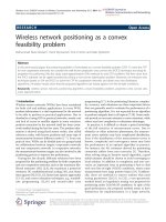
Throughput performance degradation of IEEE 802.11
in the presence of fading channels has been studied in
detail in [5]. In this paper, authors quantitatively estimated
the degradation of the network throughput due to fading.
Figure 1 shows the degradation of network throughput
versus the probability of the channel being “bad” for different
2 EURASIP Journal on Advances in Signal Processing
0.54
0.56
0.58
0.6
0.62
0.64
0.66
0.68
0.7
0.72
0.74
Saturated throughput
0.10.15 0.20.25
Probability of the channel being bad
n
= 5
n
= 10
n
= 15
n
= 20
Figure 1: Throughput degradation in IEEE 802.11 DCF mode
depending on probability of bad channel.
network sizes (n is the number of nodes in the network).
This performance degradation is due to the MAC layer not
receiving instantaneous notification of channel variations.
When the channel goes into a “bad” state, the nodes continue
sending packets, eventhough these packets are discarded
due to the low received power. This results in a waste of
bandwidth which could have been used by other nodes. In
[5], the authors proposed to improve the performance of the
IEEE 802.11 standard by utilising channel state information
(CSI). The resulting MAC only transmits packets when the
channel is such that the received signal will be above a
predetermined threshold which ensures proper detection of
the data at the receiver. Although this proposed scheme has
improved performance when compared to that of the usual
IEEE 802.11 standard, it is well below the channel capacity
[4, Chapter 16].
Therestofthearticleisstructuredasfollows.Section 2
describes related research in the field of opportunistic
medium access control mechanisms and Section 3 follows
with an explanation of the motivation for this study and
the functionality of the proposed MAC protocol. Section 4
presents an analysis of the throughput performance of the
Channel MAC mechanism. Section 5 discusses the network
simulation to calculate, throughput, delay and fairness of
the system, and the performance of Channel MAC is com-
pared with its IEEE 802.11 counterpart. Finally, Section 6
concludes this work with future research objectives.
2. Related Work
Similar to the work in [5], a mechanism for deciding which
node, from a set of nodes, should be allowed to transmit at a
given time has been presented in [6]. The basic idea exploits
the multiuser diversity principle at the MAC layer and relies
on the fact that users are competing for the channel access
experience peaks in their channels at different times, and at
a given time the node with the best transmission conditions
gets the opportunity to transmit. In [6], it was shown that if
access to the medium is given in a centralised fashion to the
user with the best channel, the throughput performance of
the overall system is improved.
In [7],QinandBerryconsideredamediumaccess
control protocol, where each user possesses knowledge of
their own channel gain. They introduced a channel-aware
ALOHA protocol where users can still exploit multiuser
gain in a decentralised way. A series of related works was
published in [8–10]. It has to be pointed out that these
proposed schemes, although exploiting diversity as a way
to determine who has priority for transmission, still use a
slotted system. Therefore, in the absence of a central entity
which would determine who will transmit based on the
“best” channel, collisions will still occur because all nodes
with good channel conditions will compete for resources at
the beginning of the slot.
The gain in throughput observed in these CSI based
MAC protocols is due to two reasons: firstly, only a reduced
number of nodes (those with a good channel) will be
competing for the available bandwidth in a given time
slot, which reduces the number of collisions and increases
the throughput. Secondly, the allowed transmissions will
be successful with a higher probability due to the high
signal quality, which reduces the number of retransmission
requests, as well as the amount of bandwidth wasted on
unsuccessful transmissions. However, in a decentralised
system, collisions can still occur unless spreading techniques
are used [9] or other collision avoidance mechanisms are
implemented, resulting in an increased number of control
packets. This will reduce the throughput performance.
We proposed a new MAC paradigm, called Channel
MAC in [11], which exploits the random nature of the
fading channel to determine the channel access instances in
a decentralised and distributed manner. In contrast to [6],
where the user with the best channel is given access to a time
slot, our proposal does not require a slotted access system.
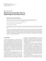
A centralised network where nodes are communicating to
an access point is shown on the left side in Figure 2.In
the literature, the multiuser diversity principle is generally
applied to this scenario. In contrast, Channel MAC considers
a decentralised network scenario shown on the right side
of the figure where different transmitter-receiver pairs are
communicating independently (i.e., without any centralised
access point).
Channel MAC uses the randomness of the fading channel
between transmitter-receiver pairs to decide which node
should transmit at a given time in a distributed manner.
The idea is that the node which has its channel becoming
“good” at a given instance gets access to the channel provided
that no one else is transmitting at that moment. This oppor-
tunity for transmission persists until the channel becomes
“bad” again. Therefore, it is a time-asynchronous channel
access mechanism. It should be noted here that Channel
MAC merely gives channel access to a “good” channel at
a given time, but not necessarily to the “best” channel.
EURASIP Journal on Advances in Signal Processing 3
Channel 1
Channel 2
Channel 3
Channel 4
Access point
Centralised network
Channel 4
Channel 1
Channel 2
Channel 3
Distributed network
Figure 2: Centralised and distributed networks.
The objective of this paper is to evaluate the effectiveness
of such a fully-distributed, but nonoptimum medium access
control mechanism in various network environments. We
will evaluate the performance of this MAC paradigm using
analytical results as well as event-based simulation results.
3. The Channel MAC Mechanism
In the related work described in Section 2 [8–10], medium
access is accomplished either in a centralised way or at each
node with the knowledge of the channel states of other nodes.
We use a fully distributed scheduling mechanism where
each node determines its channel access irrespective of the
channel conditions at other nodes.
3.1. Channel Prediction. Similar to other opportunistic com-
munication-based systems, Channel MAC requires nodes
to predict the fading channel [4]. As the objective of this
paper is to investigate whether a distributed nonideal oppor-
tunistic access scheme exploiting the channel randomness
can provide significant performance improvement, we do
not suggest a particular prediction scheme to be used in
conjunction with the Channel MAC protocol in this paper.
We provide the following discussion on fading channel
prediction to ascertain the existence of schemes that are
suited for channel prediction in Channel MAC.
Fading generally occurs due to multiple reflections of
the transmitted signal from objects in the environment.
If an unmodulated carrier at frequency f
c
is transmitted
over a fading channel, the complex envelope of the received
noiseless signal at time t, c(t), is given by
c(t)
=
N
n=1
A
n
e
j(2πf
n
t+θ
n
)
,(1)
where N is the number of scatterers. For the nth scatterer,
f
n
is the Doppler frequency, θ
n
is the phase, and A
n
is the amplitude. The parameters A
n
, f
n
,andθ
n
vary
slowly (on the order of 0.1 second [12]) and can be
viewed as fixed over a few milliseconds. Channel prediction
methods discussed in the literature can be broadly divided
into three categories, according to the underlying channel
model: autoregressive (AR), sum-of-sinusoids (SOS), and
basis expansion algorithms (band limited process model-
based, etc.) [13]. To allow for comparison between dif-
ferent schemes, the prediction range is often expressed in
“wavelengths,” λ (when the maximum Doppler shift is f
d
,
a prediction t seconds ahead corresponds to a prediction of
f
d
t wavelengths). References [12, 14] provide overviews of
long range prediction techniques for fading channels, which
include several techniques capable of predicting a channel
over more than 1 wavelength.
In the SOS model-based approach, if the parameters A
n
,
f
n
,andθ
n
in (1) remain fixed and are known perfectly,
the individual complex sinusoids can be extrapolated and
summed to produce a reliable prediction of the fading signal.
ESPRIT [15] is an example of the SOS approach. With the
ESPRIT prediction scheme, reliable prediction is feasible for
about 1 wavelength [15]. At a speed of about 10 kmph, this
corresponds to making predictions about 46 milliseconds
ahead at 2.4 GHz. Assuming that the ratio of power threshold
to root mean square (RMS) power of the received signal is
0.5, the level crossing rate for the above parameters (i.e.,
speed
= 10 kmph, frequency = 2.4 GHz) is about 35 crossings
per second. This leads to around 1.6 fades in 46 milliseconds.
Hence, with the ESPRIT scheme it is possible to predict the
channel gain for the next 1 or 2 fading cycles.
The modified covariance method discussed in [14]is
capable of predicting the channel for up to 1.5 wavelengths.
4 EURASIP Journal on Advances in Signal Processing
For the same parameters discussed above, this corresponds to
predicting the channel gain for the next 2 to 3 fading cycles.
The AR model-based methods are more appropriate
for realistic channels. The AR model-based long range
prediction (LRP) algorithm was discussed in [12]. In LRP,
the low sampling rate increases the memory span and
utilises the large side-lobes of the channel autocorrelation
function to predict the channel for multiple fading cycles.
For example, for a sampling frequency of 500 Hz, maximum
Doppler frequency of 100 Hz and model order of 20, the
memory span of channel prediction becomes 30 milliseconds
at high accuracy, compared to a memory span of 0.76
millisecond at a higher sampling frequency of 25 KHz with
the aforementioned channel configuration. (In time series
analysis, “model order” is defined as the number of previous
samples used to predict a future value.)
Band-limited process model-based prediction algorithms
are investigated in [16–18]. In these methods, the basis
functions of the subspace of time-concentrated and band-
limited sequences are determined using the AR function of
the fading channel. The extrapolated basis functions are then
used to construct predicted fading coefficients. Although
band-limited process model-based algorithms demonstrate
reliable performance for synthetic channels with stationary
parameters, performance, and complexity, investigations
for realistic channels have not been carried out for these
methods.
Based on the above cited literature, we assume that it
is possible to accurately predict the channel fading for the
next multiple fading cycles as required by the Channel MAC
protocol. However, with increasing number of nodes the
required prediction range increases as we illustrate through
the following simple example.
Assuming a constant data transmission interval l for each
transmitter-receiver pair, n transmitter-receiver pairs and fair
access the shared channel, a transmitter should access to
the channel every nl seconds. This requires a transmitter
to predict at least nl time ahead in a single-hop network
environment. In other words, if the prediction range is t,
amaximumof
t/l number of transmitter-receiver pairs
can be accommodated in the single-hop system. Hence,
the size of the network is bounded by the prediction
range. However, in practice, if the required prediction range
is very large (in case of large number of users), either
multistep (predicting the full length in a single step) or
iterated one-step predictions can be applied [19,Chapter
12]. Although, iterated one-step prediction is preferable in
terms of calculation efficiency and accuracy in general time
series analysis, this technique may suffer from the problem
of exponential divergence. However, in a large interval,
correlationinsamplesbecomesnegligible[20]. In such
systems, the mean value is considered the best prediction as
only minimal multistep errors are observed [19,Chapter4,
Chapter 12].
As the objective of this paper is to evaluate potential
performance improvement (throughput, delay, and fairness)
resulting from the proposed access paradigm, we do not
focus on the actual mechanisms used in the channel predic-
1
2
3
3
1
2
3
−6
−4
−2
0
2
4
6
8
Signal envelopes
6 8 10 12 14 16 18
Time axis
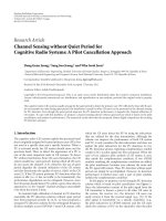
Figure 3: Data transmission using Channel MAC.
tion scheme or the potential scalability problems as discussed
in the previous paragraph. Instead, we consider a prediction
inaccuracy model, presented in [21], and evaluate the effect
of such prediction inaccuracies on the overall performance
in Section 5.1.1.
3.2. Channel MAC Protocol. In Channel MAC, a node pre-
arranges the instances at which it will send data packets
based on the predicted channel gain between the node and
the intended receiver and a signal amplitude threshold (P
th
)
for transmission. We also consider constant transmission
power in the network. When the predicted signal amplitude
goes above the P
th
threshold, the corresponding node can
potentially start transmission. However, before sending data,
a node will sense whether the channel is busy or not. If
the channel is idle, that is, no other node is currently
transmitting, the node starts transmission and continues
until the signal envelope goes below the P
th
threshold (i.e.,
the channel goes into a fade). The number of packets
transmitted during a good channel period depends on the
packet size and the duration of the good channel period.
If any other channel becomes good during transmission,
the corresponding node will sense the channel is busy and
will not transmit. It should be noted here that the carrier-
sensing threshold of the nodes is set to a much lower value
than the receiving threshold. Hence, the transmitters should
sense the medium is busy even if the channel gain between a
transmitter and an interfering node is low.
Given that each transmitter-receiver pair is likely to have
an independent fading channel, the probability of two or
more channels crossing the transmission threshold on a
positive slope exactly at the same instance is assumed to be
negligible. An instance is considered as a very small interval
on the order of 1 picosecond or less. Channel detection
time is considered negligible for a channel of size 200 KHz
or more as in [22]. However, due to finite propagation
delay, collisions can occur, decreasing the throughput. A
comprehensive analysis of collision probability in Channel
MAC and the reason why it is negligible is given in the
appendix. In case of collisions, colliding packets will be
retransmitted.
EURASIP Journal on Advances in Signal Processing 5
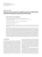
The detailed principles of Channel MAC are explained
in Figure 3.AssoonasChannel 1 (represented by 1 in
the figure) goes above the threshold, transmission for node
1 starts. Transmission is terminated as soon as the signal
amplitude goes below the threshold. Next, Channel 2 (2 in
the figure) goes above the threshold and starts transmission.
During the transmission at node 3 (its channel is 3 in the
figure), Channel 2 and Channel 1 become good but both
node 1 and node 2 will sense the channel busy and defer
transmission.
It should be noted that the Channel MAC does not rely
on a random backoff mechanism to randomise access to the
shared medium. Instead, Channel MAC uses the random
fluctuation of channels between different pairs of nodes to
randomise channel access. The decision to transmit is taken
at each node without explicit knowledge of the channel gain
between other nodes in the neighbourhood. Therefore, the
system is totally distributed.
3.3. Practical Considerations. In this section, we briefly de-
scribe some issues in implementing the Channel MAC
paradigm.
3.3.1. Start-Up Phase. To start the communication, a node
needs to predict the channel gain at the intended receiver.
To predict the channel gain, a node requires a few samples
of the previous channel gains. This can be obtained through
the received powers recorded on the acknowledgment (ACK)
packets or by sending periodic beacons. Whenever a node
needs to send a packet to a new node (i.e., start-up session
of any new transmitter-receiver pair), a series of beacon
messages can be used to measure and predict the channel
to the new node. At the start, these beacons need to be
sent randomly when the channel is idle. Once sufficient
measurements have been obtained, nodes can predict the
channel and start data transmission. A similar procedure
needs to be performed when there is a long period of
inactivity between two nodes. It should be noted here that
initially the predictions will be inaccurate and hence there
will be a period of low throughput until the prediction
accuracy becomes sufficiently high.
3.3.2. Mean Received Power Calculation. The widely used
radio signal-based distance estimation (RSS) provides high
accuracy in location measurements on the order of a meter
or better [23]. Conversely, the mean received power can be
measured if the distance information is available. We assume
each node uses the GPS or a similar scheme to estimate
its location and transmit the location, antenna gain, and
relevant information using a field in the packet. Thus each
transmitter-receiver pair knows the relative distance from
each other and can approximate the mean received power
for a constant transmitter power value. The information
required for this calculation can be sent using a field of either
control or data packets.
3.3.3. Power Threshold Selection. After measuring the mean
received power, each transmitter-receiver pair calculates
the threshold power level for the packet transmission and
reception based on the probability of a good channel, P. P
is the probability that the channel gain H
i
is above a certain
threshold H
T
,givenby[24]
P
= exp
−
H
2
T
h
2
0
,(2)
where h
0
is the average channel gain. Note that keeping
approximately the same P across all channels maintains fair
throughput in the network [11]. We assume all nodes in the
network agree on the same value of P for data transmission.
Hence, once the mean received power is estimated, a node
will estimate the channel gain threshold H
T
, using (2).
3.3.4. Acknowledgments. Once the receiving node receives
the packet, the received signal strength is estimated and
sent to the transmitting node in an ACK packet. If the
estimated received power in the current ACK packet is higher
than the threshold, the sender sends another packet to the
receiver. Otherwise, the sender defers packet transmission
and predicts the start of the next transmission instance (i.e.,
the time predicted signal strength crosses the threshold in an
upward direction).
4. Throughput Analysis of Channel MAC
In this section, the analytical throughput equations for
Channel MAC are derived and validated using a simple
Monte-Carlo simulation.
4.1. System Model. Let us define a neighbourhood of 2n
nodes, where N
T
∈ (1, 2, , n) are the transmitters and
N
R
∈ (1, 2, , n) are the receivers. For symmetry, let us
assume that each transmitter i
∈ N
T
is communicating with
receiver j
∈ N
R
.
4.2. Channel Model. We consider a simple two-state channel
model. It has either a nonfade state “ON” with gain 1 or a
fade state “OFF” with gain 0. The (ith) nonfade duration of
the
nth channel, denoted as l
ni
, is an arbitrary distributed
random variable with mean l (i.e., average nonfade duration
(ANFD) is l), where
n ∈ n, i ∈ R. Afterwards, the channel
goes into a fade with an arbitrary distributed fade duration
as shown in Figure 4. The instantaneous (ith) fading time of
the
nth channel, denoted as Θ
ni
, is a random variable with
the mean Θ,where
n ∈ n, i ∈ R. Θ is also known as average
fade duration (AFD) of the channel. Hence, the probability
of good channel, P, can be calculated as follows:
P
=
l
l + Θ
. (3)
We assume that all the channels in the network have the
same P value.
When the number of users in the network is 1 node
pair (this system is termed 1-user pair Channel MAC), the
resulting transmission pattern of the network is identical to
the channel model.
6 EURASIP Journal on Advances in Signal Processing
Arrival points of the
superpositioned
n-user pair
channel MAC
l
11
l
12
θ
11
θ
12
l
21
l
22
θ
21
θ
31
θ
32
l
31
l
32
θ
n1
l
n1
l
n2
l
n3
Resultant n-user
pair channel MAC
Channel 1
Channel 2
Channel 3
Figure 4: Two-state channel model.
We define the expected period of 1-user pair Channel
MAC, T
p
, in terms of the number of arrival points per unit
time period (i.e., level crossing rate, r) as follows:
T
p
=
1
r
= t + l,(4)
where t is the expected idle time for 1-user pair Channel
MAC.
4.2.1. Arrival Points of n-User Pair Channel MAC. We d efi ne
the “Superpositioned n-user pair Channel MAC” as the
superposition [25, pages 101–104] of arrival points of n
independent channels. We assume that, at each instance,
exactly one channel becomes good (i.e., transitions from
OFF to ON). The corresponding node can then transmit
data given that no one else is transmitting at that instance.
Following the operation of Channel MAC, we can identify
the transmission periods and idle periods of the network
with n user pairs, which we term as “Resultant n-user pair
Channel MAC” system.
Note the difference between Resultant and Superposi-
tioned n-user pair Channel MAC. In Resultant n-user pair
Channel MAC, the number of arrival points (i.e., transition
from OFF to ON) cannot be greater than the number of
arrival points in the Superpositioned n-user pair Channel
MAC. This is due to the fact that some of the arrival points of
the Superpositioned n-user pair system may not contribute
to throughput in Channel MAC operation as they may occur
while another node is transmitting.
We further assume that in Superpositioned n-user pair
Channel MAC, arrival points of individual channels are
“sparse.” That is, in any particular set
A of arrival points
occurring in a random and large time interval, there will be
with high probability, at least one point from each process. In
addition, no arrival points from one channel dominate over
others. Hence, an approximately equal number of arrival
points from different channels should be present in a large
enough time interval. These assumptions will be satisfied if
all the channels use the same P values as is the case with
Channel MAC.
4.3. Superposition of Point Processes. It is known that the
superposition of two independent renewal processes is itself
a renewal process if and only if both processes are Poisson
[26]. It is also known that the superposition of independent
and uniformly sparse processes converge to a Poisson process
as the number of processes and the sparseness increase.
Such convergence results were first examined by Palm
in 1943 and Khinchin in 1955 under rigid assumptions
[27]. A general Poisson limit theorem for independent
superpositions was obtained by Grigelionis in 1963 [28].
This theorem states that if the points of each individual
processes are (a) suitably sparse and (b) no one process
dominates the rest, the distribution of the point process is
close to Poisson. Corresponding results for point processes
generated by mixing Poisson and compound Poisson process
can be found in [29]. Similarly, practical applications such
as the superposition of arrival processes in a “single server
queuing model” consider approximation-based approaches,
where the superimposed point process is approximated as a
Poisson process [30]. All these works conclude that a Poisson
process is often a good approximation for a superposition
process if many processes are being superposed. Based on
our assumptions above, we assume that the arrival points
of the Superpositioned n-user pair Channel MAC converge
asymptotically to a Poisson process.
4.4. Expected Idle Time of Resultant n-User Pair Channel
MAC. It can be observed that the expected idle time, E[I], of
the system decreases with the increasing number of channels.
As per our assumptions, the Superpositioned n-user pair
Channel MAC is approximated by a Poisson point process.
Since the arrival points are memoryless, we derive
F
I
(x) = P(I ≤ x) = 1 −e
−nrx
∴ E[I] =
1
nr
.
(5)
4.5. Throughput Estimation. The expected period of arrival
point process for the Resultant n-user pair Channel MAC
T
p
is the summation of the expected duration of successful
transmission l andexpectedidletimeE[I]. The average
channel utilisation or throughput S of Channel MAC is given
by the ratio of l to the expected period of the Resultant n-user
pair Channel MAC [22]:
S
=
l
T
p
=
l
l + E[I]
. (6)
4.6. Model Validation. In this section, we use two distinct
channel models to verify the accuracy of the above through-
put estimations.
4.6.1. Simulation 1: Fixed l and Exponential Fade Duration.
We assume arbitrary distributions for both nonfade and fade
durations. As a special case, we consider fixed l for nonfade
duration and exponentially distributed fade duration with
mean (1/r
−l). The simulation approach we use is to generate
n independent channels with the same l and average fade
duration 1/r
− l. When one or more channel “ON” periods
EURASIP Journal on Advances in Signal Processing 7
0.4
0.5
0.6
0.7
0.8
0.9
1
Saturated throughput
0.10.20.30.40.50.60.70.80.9
Probability of good channel (P)
Analytical results: n
= 5
Rayleigh fading model: n
= 5
Fixed ANFD and exponential AFD: n
= 5
Analytical results: n
= 20
Rayleigh fading model: n
= 20
Fixed ANFD and exponential AFD: n
= 20
Figure 5: Throughput versus P for different number of node pairs.
overlap, only the first channel to go to “ON” after a nonzero
idle period contributes to the throughput.
4.6.2. Simulation 2: Rayleigh Fading Model. In the second
simulation, we generate a set of “ON” and “OFF” intervals
based on a Rayleigh fading channel. P which is equivalent
to the probability that the envelope amplitude of the
received signal H
i
is above a certain threshold H
T
,isgiven
by (2).
In the simulation, for a given P value, we derive the
signal envelope threshold, H
T
. Then, we generate a channel
model, covering a time period
T,intheformofasetoftime
intervals, Λ
={λ
1
, λ
2
, , λ
i
, }, where the signal envelope
is above the threshold H
T
. These Λ time periods are the
transmission intervals of a node when the probability of
good channel is P.Forn node pairs, n sets of independent
Λ time intervals were generated. In case of overlapping
transmission intervals from different nodes, only the first
transmission interval in the overlapping group contributes
to the throughput. We assume the same P for all nodes.
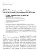
Throughput performance of the aforementioned models
for Channel MAC is presented in Figure 5. The results are
shown for a different numbers of node pairs (n
= 5 and 20)
at different probabilities of good channels. It can be observed
that the analytical results largely agree with the simulation
results for different n values over the range of channel
conditions. Furthermore, in Figure 6, the throughput versus
the number of nodes in Channel MAC using all three models
is shown at P
= .1and.85. It can be noted that, as expected,
the discrepancy between the simulation and the analytical
model decreases with increasing number of node pairs.
0.85
0.9
0.95
1
Saturated throughput
5101520
Number of user pairs
P
= .85
Analytical results
Rayleigh fading model
Fixed ANFD & exponential AFD
(a)
0.4
0.5
0.6
0.7
Saturated throughput
5101520
Number of user pairs
P
= .1
Analytical results
Rayleigh fading model
Fixed ANFD & exponential AFD
(b)
Figure 6: Throughput versus numbers of node pairs for P = .1and
P
= .85.
5. Network Simulation Using NS2
In this section, we evaluate the performance of the proposed
Channel MAC protocol through an event-based simulation.
The objective of this simulation study is to show that the pro-
posed fully-distributed medium access control mechanism
provides significant performance gains over the widely used
IEEE 802.11. The simulations in this paper are conducted
using NS2 version 2.27. We assume the fading between
different nodes is Rayleigh. However, it should be noted
here that the results can be extended to other flat fading
channels such as the Ricean channel. In this simulation
study, instead of using channel prediction we derive the
start and end of transmission periods for each channel as
follows. We generate a Rayleigh distributed fading within a
narrowband signal envelope according to the “dent model”
proposed in [31]. In the model, the carrier frequency is set
to 2.4 GHz, symbol rate is 19.2 Ksps, and node velocities
are set to 10 kmph (which corresponds to pedestrian speeds
over short time periods). The probability of good channel,
P, which is equivalent to the probability that the signal
envelope H
i
is above a certain threshold, H
T
,isgivenby
(2). Transmission intervals for all nodes in the network are
calculated as described in Section 4.6.
Nodes communicate using half-duplex radio based on
the Channel MAC mechanism at 1 Mbps. The transmission
8 EURASIP Journal on Advances in Signal Processing
range of a node is set to 250 m and the carrier sense threshold
is set to 550 m. A packet interframe space (PaIFS) is used
just before transmitting a packet. PaIFS is similar to DIFS
of IEEE 802.11 DCF mode. Between receiving a packet and
sending the ACK, a short interframe space (SIFS) is used.
PaIFS, SIFS, ACK, and MAC-PHY header values of Channel
MAC use similar values of IEEE 802.11 (basic access mode)
for comparison purposes (the MAC-PHY header and ACK
sizes are 400 and 240 bits, resp., PaIFS and SIFS durations
are 128 and 28 microseconds, resp.). The sensing delay for
each node pair is set to 0.01% of the packet transmission
time. This finite sensing delay and propagation delay will
lead to collisions. Generally, the next DATA transmission of
a node starts after getting an ACK. In the case of a collision
(i.e., no reception of ACK/timeouts), the node stops further
transmissions. For the 802.11 simulation, the basic access
method is used.
Generally, channel quality-based packet schedulers intro-
duce unfairness among the users. We assumed the same
probability of good channel P for all transmitters. Cor-
respondingly transmitter-receiver pairs fix the thresholds
according to (2)basedondifferent mean received powers.
This provides the same average nonfade durations of the
channels, which are the opportunities for packet transmis-
sion [32, Chapter 5]. Hence, the level-crossing rates (i.e., the
number of times the signal envelope crosses the threshold in
positive direction [32]) of the different channels are the same
for all node pairs. In [33], Tse and Hanly showed that such
selection of thresholds leads to fair channel access among all
nodes. Later, in a single-hop simulation setting, we measure
the throughput fairness in respect to the wireless nodes and
confirm the fairness of the Channel MAC protocol.
For the IEEE 802.11 simulation, we have used the fading
simulator extension [34] for NS2 to consider the time-
correlation of the channel based on P. The extension aids in
identifying the rms signal of the channel, R
rms
, using the two-
ray ground method. The packet reception threshold (R
th
)
based on P is derived using (2). Finally, we accept or discard
a received packet comparing its received power to the packet
reception threshold.
5.1. Simulation Scenarios and Results. In this section, we
describe the simulation scenarios and present corresponding
results. In all scenarios, we compare the throughput and
delay performance of the Channel MAC protocol with the
IEEE 802.11 protocol. We also evaluate the fairness of the
proposed protocol in a single-hop scenario and a number
of well-known multihop scenarios such as the flow-in-the-
middle scenario. In these scenarios, we calculate the fairness
measures for IEEE 802.11, Ideal MAC (collision-free), and
Channel MAC.
5.1.1. Single-Hop Scenario. In a single-hop simulation sce-
nario, we consider 2n nodes, where n nodes are transmitters
and the other n nodes are receivers, randomly distributed
in a one-hop neighbourhood. That is, each node can reach
all the other nodes in a single hop. In the simulation, we
consider n
= 5, 10, 20. Each source node generates 1000
0
0.1
0.2
0.3
0.4
0.5
0.6
0.7
0.8
0.9
1
Saturated throughput
0.40.50.60.70.80.9
Probability of good channel (P)
Channel MAC: n
= 5
IEEE 802.11: n
= 5
Channel MAC: n
= 10
IEEE 802.11: n
= 10
Channel MAC: n
= 20
IEEE 802.11: n
= 20
Figure 7: Throughput performance in single-hop scenario.
bytes UDP packets at a data rate of 1 Mbps and the data
rate of the channel is also set to 1 Mbps. This leads to a
saturated network (i.e., every node has a packet to send at
every instance) at this offered load. The MAC queue size is
set to 15 packets in both cases.
The saturated throughput (throughput achieved in a
saturated network) of Channel MAC for different probabili-
ties of good channels under Rayleigh fading is presented in
Figure 7. The performance of IEEE 802.11 under Rayleigh
fading is also shown in this figure for comparison. End-
to-end packet delay versus P for both Channel MAC and
IEEE 802.11 in single-hop case is shown in Figure 8.Ina
single-hop scenario, Channel MAC outperforms IEEE 802.11
for all values of P and all numbers of nodes. It can be
noted that for higher numbers of nodes, Channel MAC
achieves higher throughput at lower P values, increasing the
potential operating range. Furthermore, the total throughput
of the network increases with increasing number of nodes
due to multiuser diversity, contrary to the performance of
IEEE 802.11. In other words, with increasing number of
nodes, the probability of finding at least one good channel
at a given time increases, which improves the transmission
opportunities.
It should also be noted that increasing the number of
nodes leads to more collisions, which have a detrimental
effect on the throughput. However, it is evident from the
throughput result in Figure 7 that the increase in throughput
due to multiuser diversity is more than the decrease in
throughput due to collisions. At n
= 5, Channel MAC
outperforms IEEE 802.11 by 17%, and the improvement
grows to 41% for n
= 20.
EURASIP Journal on Advances in Signal Processing 9
0
0.1
0.2
0.3
0.4
0.5
0.6
0.7
End-to-end delay (s)
0.40.50.60.70.80.9
Probability of good channel
Channel MAC: n
= 5
IEEE 802.11: n
= 5
Channel MAC: n
= 10
IEEE 802.11: n
= 10
Channel MAC: n
= 20
IEEE 802.11: n
= 20
Figure 8: Delay performance in single-hop scenario.
Similar performance improvements are observed in
terms of delay. In this simulation scenario, the major
contributor to packet delay is queuing delay at the nodes.
With higher throughput, Channel MAC serves packets faster,
reducing the queuing delay, thus the reduction of packet
delay with the Channel MAC scheme.
Next, we observe the fairness performance in a single-
hop Channel MAC scenario. The fairness in resource sharing
of the wireless transmitters x
i
| i ∈ n in a single hop can be
calculated using the popular Jain fairness index [35]as
f
x
1
, , x
n
=
n
i=1
x
i
2
n
n
i=1
x
2
i
,(7)
where x
i
is the throughput of ith node.
We observe the fairness index to be above 0.98 for every
case, which is almost equal to that of IEEE 802.11 in the
similar settings. Therefore, by keeping the same probability
of good channel among every Tx-Rx pair, a fair throughput
share can be maintained in a single-hop network. IEEE
802.11 also maintains fairness which is preserved in a single
hop network.
5.1.2. Channel Prediction Inaccuracy. As we discussed earlier,
Channel MAC assumes that the channel can be predicted
accurately based on past channel values. In this section, we
use the model described in [21] to evaluate the effect of
channel prediction inaccuracies on system performances. We
define prediction accuracy as the percentage of predicted
values within a fixed prediction range/horizon. Consistent
with [5], we use a prediction accuracy of 90% in our
simulations. Figure 9 shows the throughput degradation of
0
0.1
0.2
0.3
0.4
0.5
0.6
0.7
0.8
0.9
1
Saturated throughput
Probability of good channel (p)
0.45 0.50.55 0.60.65 0.70.75 0.80.85 0.9
Channel MAC (imperfect prediction): n
= 5
IEEE 802.11: n
= 5
Channel MAC (perfect prediction): n
= 5
Channel MAC (imperfect prediction): n
= 10
IEEE 802.11: n
= 10
Channel MAC (perfect prediction): n
= 10
Channel MAC (imperfect prediction): n
= 20
IEEE 802.11: n
= 20
Channel MAC (perfect prediction): n
= 20
Figure 9: Throughput performance in a single-hop scenario
considering channel prediction inaccuracy.
01 2
34
5
Figure 10: Per-hop throughput of a 6-node multihop scenario.
Channel MAC at different node numbers due to prediction
inaccuracies. It can be observed that Channel MAC still
outperforms IEEE 802.11 for all possible values of n in case
of imperfect predictions.
5.1.3. Linear Chain Scenario. We use a 6-node linear chain
(i.e., 5 intermediate link/channels) (Figure 10) as an example
to illustrate the throughput performance of Channel MAC
in a multihop topology. The distance between consecutive
nodes is 245 m. The reception range and the carrier-sensing
range of the simulation are 250 m and 550 m, respectively.
Node 0 sends UDP traffic (packet-size of 1000 bytes) to node
5. The probability of good channels P is set to .85.
With an ideal MAC protocol (i.e., all flows are coor-
dinated to avoid collisions completely), the above linear
chain network can achieve a maximum utilisation of 1/4
[36]. However, in most practical MAC protocols, nodes in
the middle of the chain suffer more from contention and
interference than nodes at the end of the linear chain. Hence,
source nodes inject more packets into the chain than what the
next nodes can forward. As a result, packets are dropped in
10 EURASIP Journal on Advances in Signal Processing
0
0.05
0.1
0.15
0.2
0.25
End-to-end throughput (Mbps)
00.10.20.30.40.50.6
Offered load (Mbps)
Channel MAC
IEEE 802.11
Figure 11: Offered load versus end-to-end throughput (Mbps) in
the chain network at P
= .85.
the middle of the chain wasting the resources used to forward
them. The end-to-end throughput of a linear chain is hence
equal to the minimum throughput of all the intermediate
nodes [37].
In this simulation, we vary the offered load and measure
the end-to-end throughput and delay at P
= .85. The offered
load versus end-to-end throughput graph for the linear
chain scenario is shown in Figure 11. IEEE 802.11 achieves a
saturation throughput of around 0.15 Mbps, compared to a
saturation throughput of 0.23 Mbps for Channel MAC. It can
be observed in Figure 11 that, at all values of offered loads,
Channel MAC provides better throughput than IEEE 802.11.
The impact of the offered load on the end-to-end packet
delay is shown in Figure 12. As expected, the packet delay
increases with increased offered load due to the increasing
queuing delay. In Channel MAC, we observe a relatively
lower delay than IEEE 802.11 at all offered loads. This is due
to shorter queue delays at intermediate nodes due to higher
throughput with Channel MAC. In Figure 13, the saturation
throughput at different values of the probability of good
channel is given. It can be observed that the throughput
of Channel MAC is higher than that of its IEEE 802.11
counterpart for all channel conditions.
As shown in [36], IEEE 802.11 backoff mechanism is
unsuitable for ad hoc forwarding. For example, during a
transmission from node 3 to 4 (channel 4), node 0 (as it is not
aware of the transmission from node 4 to 5) may send data to
node 1 (channel 1). But node 1 will not respond with an ACK
to node 0 due to collision. As a result, node 0 will backoff and
retry. For the duration of node 3’s transmission, all attempts
by node 0 will fail, resulting in a large increase of the backoff
window. Therefore, after completion of node 3’s transmis-
0
0.5
1
1.5
2
2.5
3
Packet delay (s)
00.10.20.30.4
Offered load (Mbps)
Channel MAC
IEEE 802.11
Figure 12: Offered load versus packet delay in the chain network at
P
= .85.
0.04
0.06
0.08
0.1
0.12
0.14
0.16
0.18
0.2
0.22
0.24
Saturated end-to-end throughput (Mbps)
0.40.50.60.70.80.9
Probability of good channel (P)
Channel MAC
IEEE 802.11
Figure 13: Saturated throughput at all P values.
sion, node 0 may remain in backoff for a long time, thus
missing transmission opportunities. Furthermore, channel
fading decreases effective throughput. On the other hand,
under Channel MAC, due to the same level crossing rate
(i.e., same fading statistics), both channel 1 and 4 can capture
the medium uniformly. Therefore, node 0’s unnecessary idle
EURASIP Journal on Advances in Signal Processing 11
1
2
3
4
5
6
7
Total received throughput (Mbps)
10 20 30 40 50
Number of node pairs (n)
Channel MAC
IEEE 802.11
Figure 14: Channel MAC and IEEE 802.11 throughput for the
random network.
times due to large backoff delay are eliminated. Eventually,
the resultant throughput (0.23 Mbps at P
= .9) reaches a
level close to the maximum possible ideal MAC throughput
of 0.25 Mbps.
5.1.4. Random Network Topology. In a random network
scenario, we consider nodes randomly distributed in an area
of 1500
×1500 m
2
. We only consider single-hop flows in these
simulations. The data generation rate is 1 Mbps per node,
which generates enough data to saturate the network. The
reception and sensing range for all nodes are set to 250 m
and 550 m as before and P is set to .85. We average a large
number of simulation results to derive the throughput for a
number of nodes.
Figure 14 shows the average received throughput for both
Channel MAC and IEEE 802.11. With the number of nodes,
the received throughput increases rapidly in Channel MAC
as compared to IEEE 802.11. For n
= 10, Channel MAC
outperforms IEEE 802.11 by about 100%. The improvement
in throughput grows to around 130% for n
= 50. This
improvement is again due to the multiuser diversity gain. In
Figure 15, the end-to-end packet delay for different number
of nodes is presented. As expected, the packet delay in
Channel MAC is much lower than that of IEEE 802.11 in the
random network scenario. This is due to the fact that with
higher throughput at each node, packets are served faster
with Channel MAC, reducing the queuing delay, which is the
major contributor to delay in this scenario.
5.1.5. Flow-in-the-Middle Topology. Carrier sense multiple
access (CSMA)-based protocols like IEEE 802.11 can lead to
large differences between the observed throughput in neigh-
bouring nodes [38, 39]. This fact can be demonstrated using
0.04
0.06
0.08
0.1
0.12
0.14
0.16
0.18
0.2
End-to-end packet delay (s)
10 20 30 40 50
Number of node pairs (n)
Channel MAC
IEEE 802.11
Figure 15: Channel MAC and IEEE 802.11 end-to-end packet delay
for the random network.
Flow 1 Flow 2 Flow 3
Figure 16: Flow-in-the-middle (FIM) topology.
the flow-in-the-middle topology as shown in Figure 16,with
three flows (flow 1 to 3) across the nodes separated by 245 m.
The capture threshold, denoted as CPThreshold, is set to
10 dB, which corresponds to 445 m of signal interference
region (suppose a packet is received by a node in an interval.
If another packet transmission starts during that interval
so that the latter packet reaches the node with a power
which is CPThreshold below the received power of the first
packet, the node will be able to successfully receive the
first packet. Otherwise, both packets will not be properly
received). Sources of two neighbouring flows are separated
by more than the signal interference region but less than
the carrier sense region (550 m). Hence, flow 1 and 3 are
out of carrier-sensing range from each other. Flow 2 has a
chance to capture the medium when the other flows are idle.
Therefore, both flows 1 and 3 compete with flow 2, resulting
in throughput starvation of flow 2. This problem is known
as the flow-in-the-middle (FIM) problem. The probability
of good channel condition P is set to .75 across the entire
network in this experiment.
In Figures 17 and 18 we show the throughput of each
flow under IEEE 802.11 and Channel MAC. In IEEE 802.11
the middle flow (flow 2) receives very low throughput
12 EURASIP Journal on Advances in Signal Processing
0
0.5
1
1.5
2
2.5
Saturated end-to-end throughput (Mbps)
IEEE 802.11 Channel MAC
Flow 1
Flow 2
Flow 3
Figure 17: FIM throughput with IEEE 802.11 and Channel MAC
for P
= .75.
(almost zero), while the outer flows (flow 1 and 3) receive
throughput close to the maximum. The reason of this dis-
parity was widely investigated in the literature, for example,
in [40]. In the ideal situation, the middle flow should contend
with the two outer flows, whereas flow 1 and 3 contend
only with flow 2. Hence, the effective capacity of flow 2
ideally is upper bounded by 1/3 of its maximum capacity.
But the capacity of each outer flow can grow up to 2/3
of its maximum capacity. In the case of IEEE 802.11, each
unsuccessful transmission by flow 2 increases its waiting
period exponentially. Moreover, node 2 freezes its transceiver
most of the time since the outer flows capture the medium
frequently. Even when flow 2 wins a contention, packets
may be lost due to channel fading, further reducing the
throughput.
On the other hand, the end-to-end throughputs of
the flows increase in Channel MAC as compared to IEEE
802.11 due to the opportunistic channel diversity principle.
In Channel MAC, nodes try to capture the medium with
equal probability, resulting in a close to equal share of
resource usage for each flow. Therefore, the severe unfairness
among the saturated chains decreases in Channel MAC
by maintaining the same probability P of good channel
condition across the network. Due to the fairness in medium
access, Channel MAC operates closer to the ideal situation.
5.2. Multiple Chain Networks. In this section, we study the
interactions among multiple flows considering an N
× M
lattice network as shown in Figure 19. In each chain, nodes
are separated by 245 m. CPThreshold was set to 10 dB. Nodes
of two immediate chains are separated by 500 m. Hence,
we observe the flow-in-the-middle starvation problem [40],
where the middle chain starves due to an increased carrier
0
0.1
0.2
0.3
0.4
0.5
0.6
0.7
0.8
0.9
1
Normalised saturated throughput
IEEE 802.11 Channel MAC
Flow 1
Flow 2
Flow 3
Figure 18: FIM normalised throughput with both IEEE 802.11 and
Channel MAC for P
= .75.
Chain 1
Chain 2
Chain 3
Chain 4
M
N
Figure 19: Multihop networks.
sensing impact. Each chain consists of 6 nodes (i.e., N = 6).
Each left-most node is transmitting data to the right-most
node of its chain. Incorporating subsequent chains (e.g.,
M
= 2, 3, etc.), we investigate the end-to-end throughput
and fairness of different chains for different lattice structure
(i.e., different values of M).
The capacity of such a regular lattice structure using an
ideal MAC is given in [36]. Due to the placement of parallel
chains, every second chain can operate without interchain
interference, potentially giving 1/4 of the link capacity. The
two outer chains can use 2/3 of the link capacity, whereas the
internal chains can use 1/3 of the link capacity. Furthermore,
due to intrachain interference, the capacities of each outer
flow and internal flows finally become 1/6 and 1/12 of the
link capacity, respectively. However, in the case of two parallel
chains, each flow can use 1/2 of its link capacity.
Figures 20, 21, 22,and23 show the end-to-end through-
put for subsequent chains for different lattice structures. The
source of a chain injects more packets than the forwarding
capability of internal nodes. This is due to the fact that
EURASIP Journal on Advances in Signal Processing 13
0
0.02
0.04
0.06
0.08
0.1
0.12
0.14
0.16
0.18
Saturated end-to-end throughput (Mbps)
IEEE 802.11 Channel MAC
Flow 1
Flow 2
Figure 20: Channel MAC and IEEE 802.11 throughput for the
multihop network at P
= .9: N = 2.
forwarding rates of internal nodes are limited due to the
increased neighbour interference. This rate discrepancy leads
to higher packet loss and retransmissions in IEEE 802.11.
While these extra packets are transmitted, other nodes in
the interference range cannot transmit, leading to even lower
efficiency. Hence, the exponential backoff of IEEE 802.11
is unsuitable for such ad hoc forwarding of packets, which
is also shown in [36]. Lastly, the fading channel leads to
more throughput losses. On the other hand, the end-to-end
throughputs of the chains increase in Channel MAC in every
case as compared to IEEE 802.11.
Furthermore, we observe much reduced discrepancies
between saturated throughput for different flows with Chan-
nel MAC as compared to IEEE 802.11. For example, consider
the end-to-end saturated throughput for the lattice structure
for M
= 5 as shown in Figure 23. In IEEE 802.11, we observe
that the end-to-end throughput diminishes to zero in chains
2 and 4, whereas other chains attain higher throughput than
the mean. In contrast, this severe unfairness among the
saturated chains decreases in Channel MAC by maintaining
the same probability P of good channel condition across
the network. A comparison of the throughput for each flow
in ideal MAC, IEEE 802.11, and Channel MAC is given in
Ta bl e 1 . Due to the opportunistic and fair communication
paradigm of Channel MAC, the throughput of each flow is
close to the ideal MAC throughput.
6. Conclusion
ThegoaloftheChannelMACprotocolistouseoppor-
tunistic communication principles in a distributed manner
0
0.05
0.1
0.15
0.2
0.25
0.3
0.35
Saturated end-to-end throughput (Mbps)
IEEE 802.11 Channel MAC
Flow 1
Flow 2
Flow 3
Figure 21: Channel MAC and IEEE 802.11 throughput for the
multihop network at P
= .9: N = 3.
Table 1: Saturated throughput (Mbps) of each flow when M
= 4.
Flow
Ideal MAC IEEE 802.11 Channel MAC
(P
= 1) (P = .9) (P = .9)
1 0.17 0.15 0.14
2 0.083 0 0.08
3 0.083 0.15 0.08
4 0.083 0 0.07
5 0.17 0.15 0.14
to improve the performance of ad hoc networks. In this
paper, we model and simulate Channel MAC and show
that Channel MAC can achieve higher performance than
IEEE 802.11 in distributed wireless networks. Furthermore,
the throughput in Channel MAC increases with increasing
number of nodes, due to the multiuser diversity of the
system. It is also shown that, in a linear chain topology of 5
nodes, Channel MAC can increase the saturation throughput
by around 50%. In addition to the increased throughput, a
significant drop in the end-to-end delay is observed.
Furthermore, we investigated the starvation problem
(fairness issue) for typical network scenarios, for example,
the flow-in-the-middle topology and the chain topology
(single and multiple) under IEEE 802.11 and Channel MAC.
We have shown that by using the same P (probability of good
channel condition) in the network, the severe starvation
problem is reduced. The exponential backoff of IEEE 802.11
is unsuitable for packet forwarding in a chain network. This
problem is reduced in Channel MAC due to the channel
diversity as shown in both the single chain and multiple chain
14 EURASIP Journal on Advances in Signal Processing
Table 2: Parameters used to calculate the probability of collision in the Channel MAC.
Symbol Parameter
a Propagation delay
a Normalised propagation delay with respect to packet transmission time
n Number of nodes
l Average nonfade duration of the channel, equivalent to transmission time
r Normalised level crossing rate (LCR) of the channel with respect to packet transmission time
p
coll
Probability of collision
ρ Normalised threshold level with respect to rms signal level
d
tx
Transmission range of the sender
f
m
Maximum Doppler frequency
0
0.05
0.1
0.15
0.2
0.25
0.3
0.35
Saturated end-to-end throughput (Mbps)
IEEE 802.11 Channel MAC
Flow 1
Flow 2
Flow 3
Flow 4
Figure 22: Channel MAC and IEEE 802.11 throughput for the
multihop network at P
= .9: N = 4.
(lattice) structure. It results in a higher total throughput
as compared to IEEE 802.11 for any lattice structure. The
throughput of individual chains also becomes close to the
ideal MAC throughput.
Furthermore, we show that in a large random network
scenario, up to 130% throughput improvement can be
observed, as compared to IEEE 802.11. Therefore, we argue
that the nonideal, distributed paradigm based on the oppor-
tunistic communication principle can significantly improve
the performance of distributed wireless networks compared
to IEEE 802.11.
In this paper, we consider a single-rate data transmission.
However, a number of rate adaptive mechanisms [20, 41]at
the MAC layer have been proposed to exploit the multirate
transmission capability based on the underlying channel
conditions. We intend to address the issue of rate and power
0
0.1
0.2
0.3
0.4
0.5
0.6
0.7
Saturated end-to-end throughput (Mbps)
IEEE 802.11 Channel MAC
Flow 1
Flow 2
Flow 3
Flow 4
Flow 5
Figure 23: Channel MAC and IEEE 802.11 throughput for the
multihop network at P
= .9: N = 5.
Table 3: Analytical P
coll
at n pair of Tx-Rx.
n Approximate P
coll
in all P range of good channel
10 .001
20 .002
30 .003
50 .004
adaptation in the context of Channel MAC in the future.
Furthermore, in this paper we assume the existence of perfect
prediction schemes. In the future, we will investigate the
integration of prediction schemes with Channel MAC and
other implementation issues such as initialisation of the
network, packet headers, and channel information exchange.
EURASIP Journal on Advances in Signal Processing 15
Table 4: Simulation results of P
coll
at n pair of Tx-Rx.
nd
tx
= 10 m 30 m 50 m 70 m 90 m 110 m 250 m 550 m 1000m
5 0 0 0 0 0 0 0 0 .001
10 .0 .004 .004 .0042 .0044 .0045 .0046 .0048 .0049
20 .0006 .0008 .002 .004 .005 .005 .006 .0064 .0066
30 .0008 .002 .003 .004 .005 .008 .009 .01 .022
Table 5: IEEE 802.11 collision probability results for different
window sizes (W) and node numbers (n).
nW= 8 W = 16 W = 32
10 .47 .38 .29
20 .58 .5 .38
30 .62 .55 .45
50 .74 .63 .55
Appendix
Collision Probability in Single-Hop
Channel MAC
In this appendix, we calculate the collision probability of
Channel MAC in a single-hop network, and show why the
collision probability of Channel MAC is negligible compared
to that of IEEE 802.11.
The instance of the predicted signal amplitude crossing
the threshold in the positive direction is termed as an arrival
point in Channel MAC. We assume that the arrival point
process of a channel is Poisson. Theoretically, the probability
of arrival points for 2 or more nodes occurring at the same
instance reaches zero. However, collisions can still occur
at the receiver due to the finite propagation delays in the
network [22]. We consider constant propagation delay, equal
to the largest possible value in the network, leading to
pessimistic bounds on performance. Furthermore, due to
numerical precision error of the sensing circuitry, more than
one arrival point from different nodes can simultaneously
occur within a short interval η. In other words, η is the
precision limit. In our calculations, we assume up to 15
decimal points of precision; hence η
= 10
−15
second. We
measure the probability of collision based on Poisson arrival
points by different nodes within a distance of 250 m.
The parameters used for the calculations are collected in
Ta bl e 2 . Transmission range of the sender is assumed to be
250 m and the maximum Doppler frequency is set to 20 Hz.
Furthermore, the arrival points are assumed to be Poisson
distributed. The average nonfade duration of the channel
(packet transmission interval) and level-crossing rates are
estimated assuming the Rayleigh fading as in [32,Chapter
5]. The propagation delay and the level crossing rates
are normalised to the packet transmission interval. Then,
the probability that at least one arrival occurs within the
normalised propagation delay of an on-going transmission
is equal to the probability of collision in the system.
The results from the analytical model of (A.6)aregiven
in Ta bl e 3 ;
α
=
d
tx
3 ×10
8
=
250
3 ×10
8
second, (A.1)
ρ
=
−log(p), (A.2)
l
=
1
ρf
m
√
2π
=
1
ρ20
√
2π
,(A.3)
r
=
2πf
m
ρp ×l,(A.4)
a =
a
l
,(A.5)
P
coll
= 1 −e
−nra
. (A.6)
From (A.6), if
a → 0, then P
coll
→ 0. The collision
probabilities for different network sizes at transmission range
250 m are given in Tab le 4 and similar results for NS2
simulations for different transmission ranges and network
sizes are given in Ta bl e 4 . The small differences in collision
probabilities between the analytical and simulation results
are due to the Poisson approximation of the arrival point
process of the Rayleigh faded channels in (A.6). Further-
more, we compare the results obtained above to the collision
probability observed in IEEE 802.11 given in Tab le 5 .The
results for IEEE 802.11 are taken from [42]. This shows
a significantly higher order collision probability in IEEE
802.11. Hence, we can ignore packet collision in Channel
MAC.
Acknowledgments
The authors would like to thank Arek Dadej of The Institute
for Telecommunications Research, University of South Aus-
tralia, Stavros Toumpis, associate editor of EURASIP JASP,
and the anonymous reviewers for their careful comments
and suggestions to improve the paper.
References
[1] P. Gupta and P. R. Kumar, “The capacity of wireless networks,”
IEEE Transactions on Information Theory,vol.46,no.2,pp.
388–404, 2000.
[2] M. Grossglauser and D. N. C. Tse, “Mobility increases the
capacity of ad hoc wireless networks,” IEEE/ACM Transactions
on Networking, vol. 10, no. 4, pp. 477–486, 2002.
[3] Y. E. Sagduyu and A. Ephremides, “The problem of medium
access control in wireless sensor networks,” IEEE Wireless
Communications, vol. 11, no. 6, pp. 44–53, 2004.
16 EURASIP Journal on Advances in Signal Processing
[4] A. Goldsmith, Wireless Communications, Cambridge Univer-
sity Press, Cambridge, UK, 1st edition, 2005.
[5]P.P.Pham,S.Perreau,andA.Jayasuriya,“Newcross-layer
design approach to ad hoc networks under Rayleigh fading,”
IEEE Journal on Selected Areas in Communications, vol. 23, no.
1, pp. 28–39, 2005.
[6] R. Knopp and P. A. Humblet, “Information capacity and
power control in single-cell multiuser communications,” in
Proceedings of the IEEE International Conference on Commu-
nications (ICC ’95), vol. 1, pp. 331–335, Seattle, Wash, USA,
June 1995.
[7] X. Qin and R. Berry, “Exploiting multiuser diversity for
medium access control in wireless networks,” in Proceedings
of the 22nd Annual Joint Conference of the IEEE Computer and
Communications Societies (INFOCOM ’03), vol. 2, pp. 1084–
1094, San Francisco, Calif, USA, March-April 2003.
[8] S. Adireddy and L. Tong, “Exploiting decentralized channel
state information for random access,” IEEE Transactions on
Information Theory, vol. 51, no. 2, pp. 537–561, 2005.
[9] P. Venkitasubramaniam, S. Adireddy, and L. Tong, “Oppor-
tunistic ALOHA and cross layer design for sensor networks,”
in Proceedings of the IEEE Military Communications Conference
(MILCOM ’03), vol. 1, pp. 705–710, Monterey, Calif, USA,
October 2003.
[10] Q. Zhao and L. Tong, “Distributed opportunistic transmission
forwirelesssensornetworks,”inProceedings of the IEEE Inter-
national Conference on Acoustics, Speech, and Signal Processing
(ICASSP ’04), vol. 3, pp. 833–836, Montreal, Canada, May
2004.
[11] M. Ashraf, A. Jayasuriya, S. Perreau, and L. Rasmussen,
“Channel MAC: a novel medium access control paradigm for
wireless ad hoc networks,” in Proceedings of the Australian
Telecommunication, Networks and Applications Conference
(ATNAC ’06), pp. 404–408, Melbourne, Australia, December
2006.
[12] A. Duel-Hallen, S. Hu, and H. Hallen, “Long-range prediction
of fading signals,” IEEE Signal Processing Magazine, vol. 17, no.
3, pp. 62–75, 2000.
[13] A. Duel-Hallen, “Fading channel prediction for mobile radio
adaptive transmission systems,” Proceedings of the IEEE, vol.
95, no. 12, pp. 2299–2313, 2007.
[14] S. Semmelrodt and R. Kattenbach, “Investigation of different
fading forecast schemes for flat fading radio channels,” in
Proceedings of the 58th IEEE Vehicular Technology Conference
(VTC ’03), vol. 1, pp. 149–153, Orlando, Fla, USA, October
2003.
[15] R. Roy and T. Kailath, “ESPRIT—estimation of signal param-
eters via rotational invariance techniques,” IEEE Transactions
on Acoustics, Speech, and Signal Processing,vol.37,no.7,pp.
984–995, 1989.
[16] T. Zemen, C. F. Mecklenbr
¨
auker, and B. H. Fleury, “Time-
variant channel prediction using time-concentrated and band-
limited sequences,” in Proceedings of IEEE International Con-
ference on Communications ( ICC ’06), vol. 12, pp. 5660–5665,
Istanbul, Turkey, June 2006.
[17] R. J. Lyman and A. Sikora, “Prediction of fading envelopes
with diffuse spectra,” in Proceedings of the IEEE Interna-
tional Conference on Acoustics, Speech, and Signal Processing
(ICASSP ’05), vol. 3, pp. 753–756, Philadelphia, Pa, USA,
March 2005.
[18] R. J. Lyman, Linear prediction of continuous-time, bandlimited
processes with applications to fading in mobile radio,Ph.D.
thesis, University of Florida, Gainesville, Fla, USA, 2000.
[19] H. Kantz and T. Schreiber, Nonlinear Time Series Analysis,
Cambridge University Press, Cambridge, UK, 1999.
[20] B. Sadeghi, V. Kanodia, A. Sabharwal, and E. Knightly,
“Opportunistic media access for multirate ad hoc networks,”
in Proceedings of the 8th Annual International Conference on
Mobile Computing and Networking (MobiCom ’02), pp. 24–35,
Atlanta, Ga, USA, September 2002.
[21] A. Aguiar, H. Karl, and A. Wolisz, “Channel adaptive tech-
niques in the presence of channel prediction inaccuracy,” in
Proceedings of the 5th European Wireless Conference (EW ’04),
Barcelona, Spain, February 2004.
[22] L. Kleinrock and F. Tobagi, “Packet switching in radio
channels—part I: carrier sense multiple-access modes and
their throughput-delay characteristics,” IEEE Transactions on
Communications, vol. 23, no. 12, pp. 1400–1416, 1975.
[23] N. Patwari, R. J. O’Dea, and Y. Wang, “Relative location in
wireless networks,” in Proceedings of the 53rd IEEE Vehicular
Technology Conference (VTC ’01), vol. 2, pp. 1149–1153,
Rhodes, Greece, May 2001.
[24] W. C. Jakes, Microwave Mobile Communications, John Wiley &
Sons, New York, NY, USA, 1974.
[25] D. R. Cox and V. Isham, Point Processes, Chapman &
Hall/CRC, London, UK, 1980.
[26] E. Cinlar, “Superposition of point processes,” in Stochastic
Point Processes: Statistical Analysis, Theory and Applications,
pp. 549–606, John Wiley & Sons, New York, NY, USA, 1972.
[27] D. Schuhmacher, Estimation of distances between point pro-
cess distributions, Ph.D. thesis, University of Zurich, Zurich,
Switzerland, 2005.
[28] B. Grigelionis, “On the convergence of sums of random
step processes to a Poisson process,” Theory of Probability
Applications, vol. 2, no. 8, pp. 177–182, 1963.
[29] R. Banys, “On superpositions of random measures and point
processes,” in Proceedings of the 6th International Conference on
Mathematical Statistic s and Probability Theory, vol. 2 of Lecture
Notes in Statistic s, pp. 26–37, Wisla, Poland, 1978.
[30] W. Whitt, “Approximating a point process by a renewal
process—I: two basic methods,” Operations Research, vol. 30,
no. 1, pp. 125–147, 1982.
[31] P. Dent, G. E. Bottomley, and T. Croft, “Jakes fading model
revisited,” Electronics Letters, vol. 29, no. 13, pp. 1162–1163,
1993.
[32] T. Rappaport, Wireless Communications: Principles and Prac-
tice, Prentice Hall PTR, Upper Saddle River, NJ, USA, 2001.
[33] D. N.C. Tse and S. V. Hanly, “Multiaccess fading channels—
part I: polymatroid structure, optimal resource allocation
and throughput capacities,” IEEE Transactions on Information
Theory, vol. 44, no. 7, pp. 2796–2815, 1998.
[34] R. J. Punnoose, P. V. Nikitin, and D. D. Stancil, “Efficient
simulation of Ricean fading within a packet simulator,” in
Proceedings of the 52nd IEEE Vehicular Technology Conference
(VTC ’00), vol. 2, pp. 764–767, Boston, Mass, USA, September
2000.
[35] R. Jain, D. Chiu, and W. Hawe, “A quantitative measure of
fairness and discrimination for resource allocation in shared
computer systems,” DEC Research Report TR-301, Littleton,
Mass, USA, Digital Equipment, September 1998.
[36] J. Li, C. Blake, D. S. J. De Couto, H. I. Lee, and R. Morris,
“Capacity of ad hoc wireless networks,” in Proceedings of the
7th Annual International Conference on Mobile Computing and
Networking (MOBICOM ’01), pp. 61–69, Rome, Italy, July
2001.
EURASIP Journal on Advances in Signal Processing 17
[37] Y. Gao, D M. Chiu, and J. C. S. Lui, “Determining the end-to-
end throughput capacity in multi-hop networks: methodology
and applications,” in Proceedings of the Joint International
Conference on Measurement and Modeling of Computer Syste ms
(SIGMETRICS ’06), vol. 34, pp. 39–50, Saint Malo, France,
June 2006.
[38] C. Chaudet, I. G. Lassous, E. Thierry, and B. Gaujal, “Study of
the impact of asymmetry and carrier sense mechanism in IEEE
802.11 multi-hops networks through a basic case,” in Proceed-
ings of the 1st ACM International Workshop on Performance
Evaluation of Wireless Ad Hoc, Sensor, and Ubiquitous Networks
(PE-WASUN ’04), pp. 1–7, Venezia, Italy, October 2004.
[39] X. Wang and K. Kar, “Throughput modelling and fairness
issues in CSMA/CA based ad-hoc networks,” in Proceedings
of the 24th Annual Joint Conference of the IEEE Computer and
Communications Societies (INFOCOM ’05), vol. 1, pp. 23–34,
Miami, Fla, USA, March 2005.
[40] M. Garetto, T. Salonidis, and E. W. Knightly, “Modeling
per-flow throughput and capturing starvation in CSMA
multi-hop wireless networks,” in Proceedings of the 25th
IEEE International Conference on Computer Communications
(INFOCOM ’06), pp. 1–13, Barcelona, Spain, April 2006.
[41] G. Holland, N. Vaidya, and P. Bahl, “A rate-adaptive MAC
protocol for multi-hop wireless networks,” in Proceedings of
the 7th Annual International Conference on Mobile Computing
and Networking (MOBICOM ’01), pp. 236–251, Rome, Italy,
July 2001.
[42] H. Vu and T. Sakurai, “Collision probability in saturated IEEE
802.11 networks,” in Proceedings of Australian Telecommuni-
cation Networks and Applications Conference (ATNAC ’06),pp.
21–25, Melbourne, Australia, December 2006.