Báo cáo hóa học: " Research Article APRON: A Cellular Processor Array Simulation and Hardware Design Tool" doc
Bạn đang xem bản rút gọn của tài liệu. Xem và tải ngay bản đầy đủ của tài liệu tại đây (812.16 KB, 9 trang )
Hindawi Publishing Corporation
EURASIP Journal on Advances in Signal Processing
Volume 2009, Article ID 751687, 9 pages
doi:10.1155/2009/751687
Research Article
APRON: A Cellular Processor Array Simulation and Hardware
Desig n Tool
DavidR.W.BarrandPiotrDudek
School of Electr ical and Electronic Engineering, The University of Manchester, P. O. Box 88, Manchester M60 1QD, UK
Correspondence should be addressed to David R. W. Barr,
Received 12 September 2008; Accepted 21 March 2009
Recommended by David Lopez Vilarino
We present a software environment for the efficient simulation of cellular processor arrays (CPAs). This software (APRON) is
used to explore algorithms that are designed for massively parallel fine-grained processor arrays, topographic multilayer neural
networks, vision chips with SIMD processor arrays, and related architectures. The software uses a highly optimised core combined
with a flexible compiler to provide the user with tools for the design of new processor array hardware architectures and the
emulation of existing devices. We present performance benchmarks for the software processor array implemented on standard
commodity microprocessors. APRON can be configured to use additional processing hardware if necessary and can be used as a
complete graphical user interface and development environment for new or existing CPA systems, allowing more users to develop
algorithms for CPA systems.
Copyright © 2009 D. R. W. Barr and P. Dudek. This is an open access article distributed under the Creative Commons Attribution
License, which permits unrestricted use, distribution, and reproduction in any medium, provided the original work is properly
cited.
1. Introduction
Massively parallel processing systems have been the topic
of high-performance computing research and design for
many years [1–4], but in recent years single-chip imple-
mentations of such systems are becoming a reality. Cellular
processor arrays (CPAs) such as the ones presented in [5–
10] implement data processing at a fine-grain level of paral-
lelism. Unlike sequential and coarse-grain parallel processing
systems, such as multicore processors [11–13], which have
large and complex instruction sets, CPAs are comprised of
simpler processors, with a reduced instruction set. Typically
they are used to perform lower-level data-parallel algorithms
and operate in the Single Instruction Multiple Data (SIMD)
mode, that is, every processor executes the same instruction
but operates on their own local memories. The processors
require much less silicon area due to their simplicity
(compared to standard microprocessors) which means high
numbers of them can be placed on a device, usually arranged
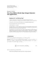
in a 2D grid (Figure 1). The massively parallel nature of
the device and spatial positioning of the processors give
performance and efficiency advantages, in particular in
data-intensive algorithms which require a high memory
bandwidth, as each processor is able to access its own
data and exchange data with its neighbours. A nonparallel
system would have to perform many instructions, including
memory sequential accesses to accomplish the same task. The
low power consumption of a CPA, significantly lower than
that of an equivalently performing sequential system (such
as a desktop PC or workstation), is an appealing property for
designers of low power embedded systems.
The highly parallel nature of CPAs has increased appeal
to a variety of fields, where many simple computations
must be performed on data arrays. The applications include
embedded vision systems [6], high-speed image process-
ing [5, 8], cellular nonlinear networks (CNNs) [7, 14],
and computational neuroscience models [15–17]. These
applications often require simple numerical operations and
neighbour communication but use operations that are
applied homogeneously to large data-sets, at high speeds.
The fine-grain nature of many CPAs means that thousands
of local memories can be operated on simultaneously, and
the simplicity of the processors allows for fast execution of
instructions.
The design of CPAs presents a set of challenges. It
requires difficult trade-offs and design decisions, such as
accuracy or speed, analogue or digital, and memory or array
size. The drive to achieve a high density of processors in
2 EURASIP Journal on Advances in Signal Processing
Global
instruction
Read-out
circuitry
Host system &
instruction
delivery micro-
controller
Cellular processor
array
Processing
element
Figure 1: An overview of a simple cellular processor array system.
a single chip often makes memory a limited resource and
reduces their computational ability. Also, the specialised
nature of the hardware often makes it less accessible to
potential application developers, while typically used short
word lengths or analogue storage techniques limit their
accuracy. Further to this, many CPAs require additional
interfaces and control systems which are specifically built for
the device, introducing additional design costs and possibly
restricting the performance of the overall CPA system.
This paper is an extended version of work presented
in [18] and presents APRON (Array Processing enviRON-
ment), a high-speed, flexible, and virtual CPA implemented
entirely in software. The software fulfils two objectives: firstly
to provide an extensible, customisable implementation of a
general purpose array processing engine, which is a basis for
the design and “virtual prototyping” of new CPAs; secondly
to provide a high-speed emulation of any CPA-based device,
allowing the user to design pixel-parallel image processing
algorithms and explore multilayer neural networks, cellular
automata, and other phenomena related to CPAs, with a
variety of tools for data analysis, performance evaluation,
and algorithm development. APRON software is written
to take advantage of the high-speeds of modern desktop
computer systems to provide optimised array processing per-
formance. To this end it is not intended to replace low-power
embedded devices but serves as a fast, accurate substitute
in environments where custom hardware is not available.
APRON has been designed to provide user-friendly tools
and achieve the maximum computational performance, with
minimal overheads, without the need for custom low-level
implementations.
This paper is organised as follows: Section 2 presents
the APRON simulation core and the integrated development
environment (IDE); Section 3 presents the potential appli-
cations/research fields where APRON can be used effectively
and how the system can emulate several types of CPA device
simultaneously; Section 4 highlights the flexible architecture
of the APRON compiler and illustrates how it can be mod-
ified to emulate or prototype hardware devices; Section 5
presents a performance analysis and benchmarks of the
APRON system. Throughout the paper, performance figures
are presented, which are summarised in the conclusion.
2. APRON System Overview
2.1. The Simulation Core. The APRON simulation core
is a platform-independent module that can be used in
many applications for fast array processing in software.
Thecoreprovidesavirtualarrayprocessor,operatingon
three data types with a flexible instruction set and a virtual
microcontroller. The microcontroller controls the program
counter which permits nonlinear sequencing of algorithm
instructions. APRON by default uses 32-bit single precision
floating point numeric representations in all operations but
it is possible to change this if necessary to lower bit-size inte-
ger types. The data types are registers, kernels, and linkmaps.
Registers are two-dimensional arrays of numeric ele-
ments called cells, which are 16-byte aligned in memory
contiguously, to facilitate cache/page management and to
take advantage of the extended x86 intrinsic architectures:
SSE (Streaming SIMD Extensions) and SSE2 [19]. These
architectures provide an SIMD vector processor in the silicon
fabric of the CPU. This vector processor can process four
single-precision floats in a minimal number of clock cycles,
providing a calculation throughput much faster than that of
the standard floating point unit (FPU). SSE also provides
cache management facilities, meaning that registers can be
pre-cached close to the processor, and even read/written
straight from/to the main system memory, without polluting
the cache if necessary. APRON registers adopt one of two
forms. A data register contains numeric data, and a mask
register contains binary data, which is used to enable and
disable the write privileges to a data register, in effect
permitting regional register operations (where global register
operations are default). For many operations, the target
register can also be a source register due to the sequencing
of instructions sent to the CPU (e.g., giving x
= x +1
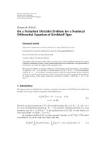
functionality). Figure 2 shows how data is sequenced, sent
to the vector processor, and combined with a mask register
to emulate the effect of disabling a processing element’s
“enabled flag”, providing local autonomy. The contents of the
target register should only be updated if the mask register’s
corresponding bit is set. This requires additional logic when
working with a vector of four elements, of which only some
of the corresponding mask register bits are set, to form a
combined result vector, which is written to the target register.
The mask register contains a 32-bit floating point NaN
(0xFFFFFFFF), for each processing element that is enabled,
and a 0 (0x00000000) for those that are disabled. Whilst at
first this may seem like a gross overuse of memory, having
all the bits set to 1 is useful for rapid logic functions; in this
case a logic OR is computed between the data register’s vector
and the corresponding mask vector. This is an efficient way
of implementing branching in the vector processor.
AkernelisanN
× N matrix used in two-dimensional
convolution/filtering operations and is applied to a register.
Kernels come in two forms. A standard kernel is used in
typical greyscale image filtering operations (convolutions),
such as Gaussian blur and gradient-detect. A template
kernel is a binary kernel used for binary pattern matching,
comprising of hits, misses, and do not cares. A logic OR
operation is performed within the domain of the kernel
EURASIP Journal on Advances in Signal Processing 3
xxxx
yyyy
cccc
xxxx
yyyy
bbbb
SSE FPU
0
b
0
b
cccc
c
b
c
b
c
0
c
0
SSE FPU (OR)
c
b
c
b
Source register 1
Source register 2
Mask register
Target register
Figure 2: Disabling processor elements is achieved by restricting writes to the register memory by using the mask register in a sequence of
logic operations. Dashed lines are memory writes, and the others are reads.
and the register, and the binary result is placed in a
result register. Unfortunately, SSE2 does not offer a simple
way of executing the kernel operation quickly, due to a
lack of efficient sideways communication within the vector
processor (however SSE3 does support this and is becoming
standard on modern processors). Instead, APRON ensures
all data required is in the highest level of cache, as close
to the processor as possible, reducing cache misses (and
eliminating paging), and the OS is stopped from swapping
out the APRON process for the duration of the operation.
Thecodeiswritteninsuchawayastobeoptimisedgreatlyby
the C++ compiler. The disassembly shows that 95 assembly
level instructions are required for a fully filtered pixel using a
3
×3matrix.
Linkmaps are a structured list of all the connections
from a single cell. APRON supports local neighbour con-
nectivity by default, so registers can be shifted and rotated
in the 4 standard compass directions, but by having no
hardware connectivity limitations, it is possible to have any
cell connected to any number of cells anywhere within
the register. Linkmaps exist for each cell in the register,
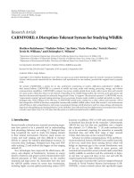
allowing unlimited connectivity possibilities. Each link is
also accompanied by a multiplicative coefficient which is
analogous to a synaptic weight (See Figure 3). When a
linkmap is used, each source register value is multiplied
by each of its connections defined by the linkmap. Each
target register value is the result of an accumulation function,
which is either a summation or maximisation of all the
multiplicative connections that link to that value’s location.
The APRON IDE allows the algorithmic generation of
linkmaps through a built-in Python interpreter and a set
of parametric maps (registers pre-filled with data), which
means the connectivity output from a register’s cell can
vary in a spatially controlled way. Linkmaps can become
large, for a fully specified linkmap of a register size N
× N;
N
4
connections are required. Often this is not the case,
so connections below a specified value are assumed to be
negligible and are omitted from the linkmap list.
A variation of the linkmap is the parametric linkmap,
in which the connectivity is described parametrically; for
example, all of the connections are based on the same
Gaussian equation, but different coefficients can change the
shape of that equation. Currently, this is computationally
time consuming and is the subject of ongoing research, as
the potential of using additional special-purpose hardware
to perform this task could greatly reduce the memory band-
width requirements of a fully connected linkmap. APRON is
a vehicle for testing various connectivity acceleration strate-
gies, whilst keeping the model structure intact, permitting
fair benchmark comparisons between each technique.
4 EURASIP Journal on Advances in Signal Processing
AB
C
1
1.4
−2.3
3.1
1.2−
1
.
7
−0.2
0.4
Source register
Target register
−2
Figure 3: Linkmaps allow multiplicative connections between the
processing cells. Each cell can be connected to any other cell.
Here, different linkmaps are shown for cells A and B, where C
=
1.7A−2.1B.
Linkmaps allow modelling of CPAs with elaborate inter-
processor connectivity patterns. However, their main use is
for implementing multilayer topographic neural networks
and other models in the field of computational neuroscience.
The use of APRON in this context will be elaborated in our
future publications.
The simulation core has been designed to be extensible,
so if necessary additional hardware (such as FPGAs or
existing processor arrays) can be used to increase the
computation speed. Currently the core supports 63 oper-
ations/instructions, including mathematical operators, reg-
ister translation, filtering, linkmap training, and external
data transfer. A simple plug-in interface permits users
to build their own modules, which can be accessed at
runtime during the simulation for transferring/computing
register and other data. In effect, this allows any form
of operation to be performed. Being a “virtual processor
array” many techniques which are difficult to implement
in hardware are relatively simple in APRON, an example
being subwindowing and scaling of registers, where isolated
regions of registers can be transferred to different locations
in other registers.
2.2. Flexible Simulation Compiler and Simulation Environ-
ment. To accompany the simulation core, a flexible com-
piler has been developed that allows the user to develop
algorithms, systems, and model devices in an intuitive way.
Consequently, a special purpose scripting language called
“APRON-Script” has been developed which is easy to use
and serves as the underlying description mechanism for
all simulations, prototypes, and algorithms. All APRON-
Script code can be checked for syntax errors and validated
automatically. The scripting language does not require
variable declaration and operates on an assumption that one
line of code corresponds to one hardware instruction. This
makes looking for performance bottlenecks and optimisation
easier. Multiple source-code files can be combined into a
single project, which is subsequently compiled into an object
code for the simulator. This promotes source-code reuse
and eases the amalgamation and distribution of projects.
The user can define environmental constraints such as the
number and dimensions of registers, constants, and macros
for a specific device they are emulating, which can be given to
other users who wish to develop algorithms for that platform.
By using a stand-alone compiler, a variety of popular source
editing tools can be used, and user-friendly attributes such as
on-line documentation and syntax highlighting are available,
promoting more rapid development.
The simulator provides tools for executing and analysing
algorithms. All registers are visually viewable as 2D images
and can be numerically inspected. The user can step through
code or enter a “run” mode, which executes the algorithms as
fast as possible. For long simulations on slower computers,
a low-priority run mode is provided. The simulator also
provides dynamic input/output with some included plug-
ins. Currently APRON provides a module to read and write
data to files, a module to interface with an imaging device
(e.g., a webcam) for capturing real-time visual input and
a module to communicate with other APRON simulations
over a network, providing a convenient way of implementing
large-scale simulations. A module could also be an interface
to external hardware devices, such as robotic arms, pan,
tilt chassis, and so forth, in effect enabling APRON to
be a development environment for intelligent systems or
autonomous agents, with sensor input, efficient image and
neural processing, and actuator output. An APRON script
algorithm can also send interrupts to the simulator to
perform tasks, such as update the display, reposition win-
dows, display performance information, issue breakpoints,
and display run-time error information. Simulations can
be terminated at any time. Each instruction is timed and
displayed, for identifying performance bottlenecks.
3. Applications
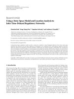
3.1. Generic Processor Array. APRON has been optimised for
speed and accuracy. Using just the default APRON-Script
instructions, it is possible to implement a wide range of
array processing algorithms. Essentially, APRON is still a
serial processing system, and so the smaller the registers, the
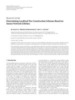
better the performance. The benchmarks in Figure 7 show
that for simple numeric operations, global register (128
×
128) operations occur in several microseconds, meaning tens
of thousands of register operations can be performed per
second. This would imply APRON could potentially be used
in both practical and research applications. Algorithms are
written in default APRON-Script, which in this scenario
can be considered a high-level language. The optimised
simulation core allows APRON to outperform popular
alternatives such as MATLAB and regular (na
¨
ıve) C/C++
implementations.
3.2. Vision Systems. The APRON simulator allows registers
to be filled with data acquired from an imaging device
(e.g., a webcam). Therefore live image data can be used
during simulation. When operating in “run” mode, many
algorithms execute fast enough to be interactive and respon-
sive to the visual input. Taking Sobel Edge detection as an
EURASIP Journal on Advances in Signal Processing 5
G
x
=
+1 +2 +1
000
−1 −2 −1
× AG
y
=
+1 0 −1
+2 0
−2
+1 0
−1
× A
G
=
G
2
x
+ G
2
y
Figure 4: The Sobel Operator equations, used in APRON bench-
marks, where G is the result of a filtered pixel at location (x, y), and
A is the unfiltered image.
example (see Figure 4), APRON can complete this algorithm
for a 128
× 128 array in 0.5 ms. Imaging devices vary in
capturing/transfer time, but webcams typically take between
10 and 100 ms to both capture and transfer an image into
APRON. Therefore, a complete capture-process cycle can
take 10.5 ms, giving a frame-rate of 95 fps. Higher quality
cameras may bring this down to 2 ms, giving 400 fps. Vision
systems implemented in the APRON virtual array processor
can be considered similar to pixel-parallel vision chip systems
[20]. For 3
× 3 filtering of a 128 × 128 array, APRON has a
throughput of 81 MP/s (Mega-Pixels/Second) and for simple
operations (add/multiply) 958 MP/s; for 512
× 512 this is
51 MP/s and 244 MP/s, respectively. For comparison, in [21],
a3
×3 filter on a 3.0 Ghz Pentium4 processor gives 9.7 MP/s;
a Xilinx Virtex-II Pro, 202 MP/s; an nVidia 6800 Ultra GPU,
278 MP/s. These results do not take into consideration any
other processing or communication requirements, unlike
APRON. It may often be the case that actually transferring
the data to/from these devices has a substantially negative
effect on the performance of the system as a whole.
3.3. Cellular Nonlinear Networks. APRON is easily config-
ured to behave as a Cellular Nonlinear Network (CNN), for
example, implementing the classical Chua model [22]. As
with the Vision System description previously, an imaging
device can be used as input. The performance of the model
varies with the array size and the type of algorithm executing
(timing and iteration requirements vary). For example,
APRON can perform the “greyscale feedback convolution”
task in 180 μs, which could be compared with results
presented in [7].
3.4. Topographic Neural Network Models. These models often
represent abstractions of known neuroanatomy, where neu-
rons are grouped into layers and can have complex interlayer
connectivity, such as those described in [15–17]. Usually
special purpose software is developed to simulate such
models as in [23], but APRON can be configured to perform
these simulations taking advantage of its optimised routines.
The high numerical precision and specific instruction set of
APRON enables the implementation of many types of neural
network models, using array registers in a way similar to
that in [24]. Unlike hardware processor arrays, APRON has
fewer limitations on resources used, supporting over 32 000
registers (of a maximum 2048
× 2048 elements). Neurons
are arranged into homogeneous layers, the size of a register;
however, the neuron parameters need not be homogeneous.
For example, a layer of Izhikevich [25]neuronscanbe
implemented using 2 registers to store the states, 1 register
to store the spike output, and several temporary registers
for calculating the state update. Network connectivity is
provided through the use of linkmaps described previously.
On a 1.8 GHz Intel Core2 Duo processor, an Izhikevich
neuron takes approximately 21 ns to update, potentially
allowing over 45 000 neurons to be updated in real time
with a 1 ms time step. Gaussian receptive fields can be
implemented either through linkmaps or by using a Gaussian
blurring filter on a register filled with the output of the layer
[24]. A single 3
× 3 blurring filter applied to a 128 × 128
register takes approximately 170 μs.
Combining the “virtual” vision chip and processor array
results in a powerful modelling tool suitable for use in
retinal and visual-cortical simulations, often in a more
controllable environment than that delivered by hardware-
oriented systems. This flexibility allows the developer to
create entire “system-on-virtual-chip” applications that may
execute at speeds suitable for practical application use.
4. Hardware Prototyping/Emulation
One definite benefit a software CPA has over hardware is
the relatively unlimited possibilities for processor element
complexity, communication strategy, and memory resources.
APRON provides many optimised operations (here consid-
ered low level) which can be combined to form higher-level
more complex macros. This ensures that the CPA designer
is using optimised code to implement the functionality of a
cell’s processing element. APRON provides at the very least
the ability to read and write to each cell individually, which
is sufficient to implement the most complex and diverse
operations.
4.1. Customizing APRON for Device Emulation. Figure 5
shows the data flow through the APRON compiler and
simulator. The APRON compiler has three levels of abstrac-
tion. The highest is the scripting language itself, which is
human readable, and consists of a combination of APRON
instructions and macros. A macro is similar to a function,
in that it encapsulates many APRON instructions into what
appears to be a single instruction, except it becomes explicitly
unrolled into the instruction sequence rather than placed
onto the stack when called. Macros have global bodies,
that is, they can access any resource, but have local labels
and variables as well, to maintain the encapsulation. For
example, in the scenario where the same macro is called
twice, it is important not to have one macro jump to
instructions in the other macro. Macros are defined in
external “ruleset” files (akin to “header files” programmed
in APRON-Script syntax), which also define resource name
changing, constant declaration, operator overloading, and
some environmental properties such as Register dimensions.
The simulator provides a facility to debug the macros
verbosely, in order to find errors in the ruleset.
Using macros, a cellular processor array designer could
specify the complete instruction set of a hardware device,
knowing the APRON instructions will deliver repeatable
results. This is useful for both the emulation of existing
6 EURASIP Journal on Advances in Signal Processing
User-defined macros
User-defined bit stream
(ICWs)
APRON-defined bit stream
(ICWs)-low-level
APRON script (human readable)-high-level
Algorithm
User
hardware
APRON simulator
APRON
hardware
APRON
software
User
simulator
APRON object code (machine readable)-medium-level
User-defined
translation rules
User-defined plug-in
interface
User
output
APRON compiler
Figure 5: APRON Compilation/System Diagram. The shaded
regions show user configurable components that customize
APRON. The boxed region indicates components that need to be
programmed and imported as a dynamic library.
hardware and the prototyping of new hardware. The designer
could build several rulesets, describing the hardware at
different levels of abstraction, from an accurate, slower
model of the analogue current or bit transfers/operations
in the individual cells to a faster, abstract behavioural
model of the device. In particular, when designing analogue
processor arrays, it is possible to model low-level circuit and
device behaviour including spatial and temporal noise, by
emulating such components. Although APRON does not
simulate these effects intrinsically (i.e., there is no dedicated
support for individual device characteristics), they can be
sufficiently modelled using the constructs APRON provides
to create accurate real-world behaviours, allowing algorithm
designers to take phenomena such as nonlinearities, error
propagation, and device mismatch into account [26]. The
APRON IDE already provides the tools for the development
and analysis of algorithms and a fast interactive simulation
tool; therefore, the designer does not have to create any
software himself. The “ruleset” can be distributed to any
user that wishes to develop algorithms for the particular
CPA. This approach has been applied successfully to the
ASPA vision chip [5], and APRON is used for algorithm
development for that device. APRON will also be used for
the development of SCAMP devices [6].
The middle layer of abstraction is APRON object code,
which is a machine readable structure defining each instruc-
tion in the APRON-Script algorithm, after all necessary pre-
processing (such as macro unrolling) has been applied. This
structure breaks down the script instruction into a function
name and a variety of parameters. The object code by default
is then turned into a binary Instruction Code Word (ICW)
stream. A single object-code instruction can consist of many
ICWs. The ICW stream is the lowest level of abstraction in
the APRON system. This stream is delivered to the APRON
Core for execution
The module responsible for the translation from object
code to an ICW stream is hot swappable, with a defined
interface, meaning it is possible for designers to create their
own ICW streams. This has the following several benefits.
(1) The user can use the APRON environment as a code
editor/compiler for a custom CPA.
(2) The ICWs can be delivered to other applications, and
even hardware devices.
(3) The ICWs can be delivered to a custom simulation
core, by passing the APRON Core entirely, providing
a highly customised simulation, but utilising the
development environment and tools APRON pro-
vides.
(4) It is similar to 3 but actually uses a hardware device
and APRON as a software interface or graphical user
interface to the hardware.
4.2. Modelling ASPA in APRON. TheASPAvisionchip
[5] is a digital cellular processor array, which contains
a bit-serial/bit-parallel synchronous data path as well as
asynchronous wave-propagation circuitry. This allows a wave
edge to be propagated across the CPA in a single instruction,
very quickly. Therefore it has many applications in more
complex image processing tasks, such as skeletonisation and
object identifying. The traditional approaches to building a
complete CPA system involve building the device, then build-
ing an accompanying interface system, and then designing
some compiler and simulation tools. APRON is being used
for the latter, with a little customisation.
Firstly, the APSA instruction set was completely mod-
elled in detail in APRON, by defining a ruleset, which
is a set of macros built entirely in APRON-Script, one
corresponding to each ASPA instruction. This limits the
algorithm developer to only using these macros and therefore
only using valid ASPA instructions. The resulting “ASPA-
Script” can be compiled in two ways. The first is to generate
the actual hardware ICWs and store them in a file, which
can subsequently be used to program the ASPA device. (The
hardware ICWs may differ from those that are created for the
simulator and can be defined algorithmically as part of the
macro definitions.) The second is to unroll the ASPA-Script
macros back into APRON-Script and run this code in the
simulator. The process of simulating when using a ruleset is
invisible to the algorithm developer, as the simulator presents
the ASPA-Script for debugging and analysis. The detail of
the ruleset can be targeted for different types of simulation.
The most detailed simulation involves modelling the bit-
level transfers between the registers in ASPA, providing good
debugging information at the expense of performance. A
higher-level simulation may assume the user is using 8-bit
integers and model the device at that level, providing an
adequate simulation of the device at high speed.
EURASIP Journal on Advances in Signal Processing 7
!macro def
propagate(0)
!macro begin
r[P FLAG]
= 0
r[AUX2]
= mask(r[C FLAG], <=,0)
maskon(r[AUX2])
r[P
FLAG]
= 255
:#START
:glob
sum
= 0
r[AUX1]
= r[P FLAG]%kernel[OR KERN]
r[AUX2]
= mask(r[AUX1], >,0)
maskon(r[AUX2])
r[AUX1]
= 255
maskoff(0)
maskoff(0)
maskoff(0)
maskoff(0)
r[AUX2]
= mask(r[PFL], >=,1)
maskon(r[AUX2])
r[AUX1]
= 0
r[AUX3]
= r[P FLAG]−r[AUX1]
r[AUX2]
= mask(r[AUX3], !=,0)
maskon(r[AUX2])
r[AUX3]
= 1
:glob
sum
= sum(r[AUX3])
r[P FLAG]
= r[AUX1]
jumpif(:glob sum, >, 0.0, :#START)
!macro end
···
···
r[PFL] = 0
vr
= 255
sub
glob(r[C], r[A], vr)
if(C)
r[PFL]
= 255
endif(0)
vr
= 250
sub glob(r[C], r[B], vr)
propagate(0)
r[C]
= 0
···
···
APRON-SCRIPT MACRO ASPA-SCRIPT ALGORITHM
Figure 6: APRON Macro definition of the ASPA function “propagate()”. On the right is a snippet of ASPA-Script assembled from macros.
On the left is an expansion of the propagate macro written in APRON-Script.
Table 1: Descriptions of the benchmark tests performed.
Te s t
Description
ADD
Two registers were filled with random values. The
two registers were added and written to a third
separate register 10 000 times.
MULT
Same as ADD, but with a multiply operation.
CONDMULT
Same as MULT, but the two registers were
multiplied, only where the contents of register 1
are greater than θ, using a mask register.
FILTER
One register was filled with random values. A
3
×3 Gaussian Blur Kernel was used to filter the
register and the result was written to a second
separate register, repeated 10 000 times.
As an example, Figure 6 shows an implementation of the
ASPA “propagate()” function, which has been implemented
in APRON-Script. Even though this is one instruction on
an ASPA device, it needs several looped APRON operations.
However, when the instruction is simulated, it will behave as
a single step. This process is transparent to the user and often
fast enough due to the efficient operations provided by the
APRON core.
The ASPA ruleset is a portable definition of the ASPA
device, with which other developers can rapidly create
algorithms for the chip, without having the hardware to test
them on. This has been achieved without needing to build a
custom simulator for the ASPA device. The plug-in feature
of APRON can be exploited for additional functionality,
including being used as an interface to an actual ASPA device.
This makes APRON a complete design, test, and develop-
ment suite for the ASPA. At present a hardware interface has
been implemented successfully for the SCAMP device, where
frames of preprocessed data from the SCAMP device can be
operated on further by efficient APRON routines.
5. Benchmarking
Throughout the development of APRON, a great effort has
been made into optimizing the APRON Core, to make it
as fast as possible. In order to assess its performance, a set
of benchmarks were compiled that measure the execution
time of commonly used operations and the performance
of APRON, MATLAB (7.01), and unoptimised high-level
8 EURASIP Journal on Advances in Signal Processing
0E +00
4E
−04
8E
−04
1.2E
−03
Time (s)
ADD MULT CONDMULT FILTER
Operation times for 128
×128 registers
0E +00
5E
−03
1E
−02
1.5E
−02
2E
−02
2.5E
−02
Time (s)
ADD MULT CONDMULT FILTER
Operation times for 512
×512 registers
0E +00
3E
−02
6E
−02
9E
−02
1.2E
−01
Time (s)
ADD MULT CONDMULT FILTER
AMD MATLAB, 1.8 GHz Opteron 265, 1GB RAM
AMD na
¨
ıve C++, 1.8 GHz Opteron 265, 1GB RAM
INTEL na
¨
ıve C++, 1.8GHzCore2Duo,2GBRAM
AMD APRON, 1.8 GHz Opteron 265, 1GB RAM
INTEL APRON, 1.8GHzCore2Duo,2GBRAM
Operation times for 1024
×1024 registers
Figure 7: Benchmarks showing the performance of different array
processing operations on different software platforms.
(na
¨
ıve) C++ is compared. The tests performed are described
in Ta bl e 1 , and the results are shown in Figure 7.
Two test machines were used with similar specifications, a
1.8 GHz AMD Opteron 265, running Microsoft Windows XP,
and a 1.8 GHz Intel Core2 Duo running in Windows Vista.
It was not possible to benchmark MATLAB programs on
the Intel platform at this time. The benchmark results show
that APRON is faster than MATLAB at all tasks, often by a
factor of 3, and faster than a na
¨
ıve C++ approach in almost
all cases. The results have shown interesting differences
between Intel and AMD processors, with AMD being on
the whole slower. This is most likely due to the nature
of AMD’s implementation of Intel’s SSE technology. The
operating system’s memory/process management system also
contributes to the performance, and this can be seen in the
results of the larger register filtering tests, as SSE is not used
for this operation.
APRON performs 128
×128 array operations using single
precision floats in tens of microseconds, which is suitable
for a great range of experiments and applications. Execution
times can largely be reduced four-fold if the change to using
8-bitintegersismade.
6. Conclusion
This paper introduced an efficient software package used
for the simulation and prototyping of cellular processor
arrays. This software is useful throughout the life cycle
of a cellular processor array-based device, from the initial
design, modelling, and prototyping of the hardware, through
to being used as an algorithm development platform, a
simulator, and even a hardware interface. An example
application of modelling a hardware CPA was presented, and
the benefits that APRON provided to the user experience of
working with the CPA were highlighted. APRON software
proves to be faster than other software (and some hardware)
environments for the tasks of emulating, prototyping, and
simulating cellular processor arrays and can even be used as a
stand-alone “array processing” system in many applications.
Software tools like APRON can encourage the “massively-
parallel” programming style and provide tools that ease
the transition from software to massively parallel hardware
implementations.
It is interesting to see that “virtual” massively-parallel
devices created in software are beginning to compete with
custom ICs and FPGAs in terms of computational per-
formance, at comparatively lower cost. With commercial
CPU manufacturers producing more parallel, lower power
devices, perhaps software environments such as APRON will
become more appealing to researchers interested in fine-
grain processor arrays and their applications in areas such
as computational neuroscience and image processing.
Acknowledgment
This work has been supported by the EPSRC, Grant no.
EP/C516303.
References
[1] K. E. Batcher, “Design of a massively parallel processor,” IEEE
Transactions on Computers, vol. 29, no. 9, pp. 836–840, 1980.
[2] S. F. Reddaway, “The DAP approach,” in Infotech State of the
Art Report on Supercomputers, vol. 2, pp. 309–329, Infotech
International, Maidenhead, UK, 1979.
[3] W. D. Hillis, The Connection Machine, MIT Press, Cambridge,
Mass, USA, 1985.
[4] Y. I. Fet, Parallel Processing in Cellular Arrays, John Wiley &
Sons, New York, NY, USA, 1995.
[5] A. Lopich and P. Dudek, “Global operations on SIMD
cellular processor arrays: towards functional asynchronism,”
in Proceedings of the International Workshop on Computer
Architectures for Machine Perception and Sensing (CAMPS ’06),
pp. 18–23, Montreal, Canada, September 2006.
EURASIP Journal on Advances in Signal Processing 9
[6] P. Dudek, “Implementation of SIMD vision chip with 128 ×
128 array of analogue processing elements,” in Proceedings of
IEEE International Symposium on Circuits and Systems (ISCAS
’05), vol. 6, pp. 5806–5809, Kobe, Japan, May 2005.
[7] A. Zarandy, M. Foldesy, P. Szolgay, S. Tokes, C. Rekeczky, and
T. Roska, “Various implementations of topographic, sensory,
cellular wave computers,” in Proceedings of IEEE International
Symposium on Circuits and Systems (ISCAS ’05), vol. 6, pp.
5802–5805, Kobe, Japan, May 2005.
[8] A. Rodr
´
ıguez-V
´
azquez, G. Li
˜
n
´
an-Cembrano, L. Carranza, et
al., “ACE16k: the third generation of mixed-signal SIMD-
CNN ACE chips toward VSoCs,” IEEE Transactions on Circuits
and Systems I, vol. 51, no. 5, pp. 851–863, 2004.
[9] M. Laiho, J. Poikonen, P. Virta, and A. Paasio, “A 64
×
64 cell mixed-mode array processor prototyping system,” in
Proceedings of the 11th IEEE International Workshop on Cellular
Neural Networks and Their Applications (CNNA ’08), Santiago
de Compostela, Spain, July 2008.
[10] J. A. Kahle, M. N. Day, H. P. Hofstee, C. R. Johns, T. R.
Maeurer, and D. Shippy, “Introduction to the cell multipro-
cessor,” IBM Journal of Research and Development, vol. 49, no.
4-5, pp. 589–604, 2005.
[11] D. Wentzlaff,P.Griffin, H. Hoffmann, et al., “On-chip
interconnection architecture of the tile processor,” IEEE Micro,
vol. 27, no. 5, pp. 15–31, 2007.
[12] L. Seiler, D. Carmean, E. Sprangle, et al., “Larrabee: a
many-core
×86 architecture for visual computing,” ACM
Transactions on Graphics, vol. 27, no. 3, article 18, pp. 1–15,
2008.
[13] W. J. Dally, U. J. Kapasi, B. Khailany, J. H. Ahn, and A. Das,
“Stream processors: progammability and efficiency,” ACM
Queue, vol. 2, no. 1, pp. 52–62, 2004.
[14]D.BalyaandT.Roska,“FaceandeyedetectionbyCNN
algorithms,” Journal of VLSI Signal Processing Systems for
Signal, Image, and Video Technology, vol. 23, no. 2-3, pp. 497–
511, 1999.
[15] B. E. Shi, “An eight layer cellular neural network for spatio-
temporal image filtering,” International Journal of Circuit
Theory and Applications, vol. 34, no. 1, pp. 141–164, 2006.
[16] J. Sirosh and R. Miikkulainen, “A unified neural network
model for the self-organization of topographic receptive fields
and lateral interaction,” in Proceedings of the Joint Conference
on Information Scie nces (JCIS ’94), pp. 282–285, Durham, NC,
USA, November 1994.
[17] D. Balya and B. Roska, “Cellular wave computing the
multi-channel mammalian retina model by the Bi-I camera-
computer,” in Proceedings of the 10th IEEE International
Workshop on Cellular Neural Networks and Their Applications
(CNNA ’06), pp. 1–12, Istanbul, Turkey, August 2006.
[18] D. R. W. Barr and P. Dudek, “A cellular processor array
simulation and hardware prototyping tool,” in Proceedings
of the 11th IEEE International Workshop on Cellular Neural
Networks and Their Applications (CNNA ’08), pp. 213–218,
Santiago de Compostela, Spain, July 2008.
[19] Intel, AP-809, “Real and complex FIR filter using streaming
SIMD extensions,” version 2.1, January 1999.
[20] D.R.W.Barr,S.J.Carey,A.Lopich,andP.Dudek,“Acontrol
system for a cellular processor array,” in Proceedings of the 10th
IEEE International Workshop on Cellular Neural Networks and
Their Applications (CNNA ’06), pp. 176–181, Istanbul, Turkey,
August 2006.
[21] B. Cope, P. Y. K. Cheung, W. Luk, and S. Witt, “Have GPUs
made FPGAs redundant in the field of video processing?”
in Proceedings of IEEE International Conference on Field-
Programmable Technology (FPT ’05), pp. 111–118, Singapore,
December 2005.
[22] L. O. Chua and L. Yang, “Cellular neural networks: applica-
tions,” IEEE transactions on circuits and systems, vol. 35, no.
10, pp. 1273–1290, 1988.
[23] J. A. Bednar, “Understanding neural maps with topographica,”
Brains, Minds, and Media, vol. 3, Article ID bmm1402, 2008.
[24] D. R. W. Barr, P. Dudek, J. M. Chambers, and K. Gurney,
“Implementation of multi-layer leaky integrator networks on
acellularprocessorarray,”inProceedings of IEEE International
Joint Conference on Neural Networks (IJCNN ’07), pp. 1560–
1565, Orlando, Fla, USA, August 2007.
[25] E. M. Izhikevich, “Simple model of spiking neurons,” IEEE
Transactions on Neural Networks, vol. 14, no. 6, pp. 1569–1572,
2003.
[26] P. Dudek, “Accuracy and efficiency of grey-level image filtering
on VLSI cellular processor arrays,” in Proceedings of IEEE
International Workshop on Cellular Neural Networks and Their
Applications (CNNA ’04), pp. 123–128, Budapest, Hungary,
July 2004.