Báo cáo hóa học: " Research Article Interference Mitigation Technique for Coexistence of Pulse-Based UWB and OFDM" doc
Bạn đang xem bản rút gọn của tài liệu. Xem và tải ngay bản đầy đủ của tài liệu tại đây (924.3 KB, 11 trang )
Hindawi Publishing Corporation
EURASIP Journal on Wireless Communications and Networking
Volume 2008, Article ID 285683, 11 pages
doi:10.1155/2008/285683
Research Article
Interference Mitigation Technique for
Coexistence of Pulse-Based UWB and OFDM
Kohei Ohno and Tetsushi Ikegami
Department of Electronics and Communications, Meiji University, 1-1-1 Higashimita, Tama-ku,
Kawasaki, Kanagawa 214-8571, Japan
Correspondence should be addressed to Kohei Ohno,
Received 31 May 2007; Revised 16 December 2007; Accepted 4 February 2008
Recommended by Ryuji Kohno
Ultra-wideband (UWB) is a useful radio technique for sharing frequency bands between radio systems. It uses very short pulses to
spread spectrum. However, there is a potential for interference between systems using the same frequency bands at close range. In
some regulatory systems, interference detection and avoidance (DAA) techniques are required to prevent interference with existing
radio systems. In this paper, the effect of interference on orthogonal frequency division multiplexing (OFDM) signals from pulse-
based UWB is discussed, and an interference mitigation technique is proposed. This technique focuses on the pulse repetition
cycle of UWB. The pulse repetition interval is set the same or half the period of the OFDM symbol excluding the guard interval to
mitigate interference. These proposals are also made for direct sequence (DS)-UWB. Bit error rate (BER) performance is illustrated
through both simulation and theoretical approximations.
Copyright © 2008 K. Ohno and T. Ikegami. This is an open access article distributed under the Creative Commons Attribution
License, which permits unrestricted use, distribution, and reproduction in any medium, provided the original work is properly
cited.
1. INTRODUCTION
Spectrum sharing technologies are attractive since there is
a real lack of frequency bands for radio systems. Cognitive
radio is one approach to coexisting radio systems. Ultra-
wideband (UWB) is also able to share spectrum with other
systems by spreading spectra extremely widely [1]. However,
in UWB systems, a potential for interference exists when
systems operate in the same frequency band. The Federal
Communication Commission (FCC) allocated a frequency
band for UWB from 3.1 GHz to 10.6 GHz and determined
transmission power to be a maximum of
−41.3 dBm/MHz
in 2002 [2]. Detection and avoidance (DAA) techniques are
required in both Japanese and European regulations to emit
−41.3 dBm/MHz in the 4 GHz band [3, 4].
The effect of interference from UWB on narrow band
systems has been evaluated by hardware experiments and
computer simulations [5–7]. In multiband-orthogonal fre-
quency division multiplexing (MB-OFDM) UWB systems,
interference is detected using FFTs in the OFDM receiver.
Null subcarriers are used for interfering bands [8]. Adaptive
pulse waveform techniques are investigated as interference
mitigation techniques in pulse-base UWB systems. UWB
pulses consist of several narrow pulses that are combined
to suppress an interfering band spectrum [9, 10]. Different
interference characteristics are reported with changing the
pulse repetition frequency and the center frequency of nar-
row band systems [7]. Low duty cycle (LDC)-UWB is recog-
nized by European regulation as a DAA technique, since the
average power is reduced by determining the maximum peak
power [4]. Critical interference mitigation techniques are less
favored. It is necessary to consider power consumption and
transmitter-receiver hardware size for potential UWB system
applications when DAA techniques are investigated.
The effect of interference from UWB on various kinds
of systems is investigated, and a multicarrier type template
wave to mitigate the influence of IEEE802.11a interference
is proposed [11].Theproposedtemplateiseffective not
only for narrowband interference such as that produced
by existing wireless LAN systems, but also for wideband
interference such as that produced by MB-OFDM. This is
achieved using a multicarrier template and hopping band
detection [12]. The technique can be also applied to the DAA
technique [13].
In this paper, a technique to mitigate interference on
OFDM signals from pulse-based UWB (p-UWB) is exam-
ined using a physical layer approach. The proposed system
focuses on pulse repetition interval in UWB assuming a
2 EURASIP Journal on Wireless Communications and Networking
Data
Primary
modulation
mapping
Serial
to
parallel
IFFT
Parallel
to
serial
DAC
BPF
Carrier
frequency
Tx
Data
De-mapping
Parallel
to
serial
FFT
Serial
to
parallel
ADC BPF
Carrier
frequency
Rx
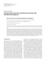
Figure 1: OFDM transmitter-receiver structure.
simple transmitter-receiver structure and a low-data rate
personal area network (PAN) system. OFDM signals have
a common modulation scheme for high-data rate wireless
systems such as wireless LANs or mobile systems. In this
paper, direct sequence (DS)-UWB is also discussed in
relation to the effectiveness of the proposed mitigating
methods.
This paper is organized as follows. In Section 2, the sys-
tem models of UWB and OFDM are explained. In Section 3,
Section 3.1, simulation results for the pulse repetition cycle
are shown. The mechanism for the proposed interference
mitigation technique and discussion of simulation results
are considered in Section 3.2.InSection 4, the proposed
interference mitigation technique is applied to a DS-UWB
system.
2. SYSTEM MODEL
2.1. Pulse-based UWB
A pulse-based UWB (p-UWB) signal can be expressed:
s
uwb
(t) =
∞
i=0
d
i
s
0
t − iT
r
,(1)
where T
r
is the pulse repetition interval, i denotes ith pulse,
d
i
is modulated data, and s
0
(t) is the UWB pulse waveform,
such as monocycle, sinusoidal wave enveloped with various
waveforms, or differentials of Gaussian functions. Here,
UWB pulse bandwidth is assumed to be wider than OFDM
signals, and Bi-Phase modulation is adopted. Thus, d
i
denotes +1 or −1.
2.2. OFDM
OFDM is a common modulation scheme. It is used for
many wireless systems, for example, wireless local area
networks (LANs). OFDM is also expected to be a next
generation mobile and wireless metropolitan area network
(MAN) system since it has many advantages in bandwidth,
transmission rate, and antimultipath effect, and so forth.
A typical ODFM signal can be expressed:
s
ofdm
(t)
= Re
∞
h=0
s
B
t − hT
SYM
·w
t − hT
SYM
·exp
− j2πf
c
t
,
w(t)
=
⎧
⎨
⎩
1
T
GI
<t<T
FFT
+ T
GI
,
0
t<T
GI
, t>T
FFT
+ T
GI
,
(2)
s
B
kT
FFT
N
=
N−1
l=0
d
c
l
+ jd
s
l
exp
j2πkl
N
,(3)
where, N is the number of subcarriers, f
c
is a carrier
frequency, and l and h are lth subcarriers in the hth
symbol, respectively. d
c
l
and d
s
l
are transmitting data after
primary modulation. T
FFT
and T
GI
are the IFFT/FFT period
and guard interval duration, respectively. T
SYM
is symbol
duration including T
FFT
, T
GI
,andacyclicprefixduration
T
cp
. w(t) denotes a window function for IFFT. The window
function is assumed to be rectangular, that is, “1” in the
symbol and “0” elsewhere. The OFDM transmitter-receiver
structure is shown in Figure 1 [14].
In this paper, OFDM systems are used unchanged in
relation to interference mitigation, because it is difficult to
change the specifications of existing systems after standard-
ization. We can assume that it is impossible to synchronize
the timing of the UWB and OFDM systems to mitigate
interference.
K. Ohno and T. Ikegami 3
Table 1: Simulation parameters for MB-OFDM and IEEE802.11a.
Parameter MB-OFDM IEEE802.11a
N: Number of FFT point 128 64
Band width: BW 528 MHz 20 MHz
D
F
: Subcarrier frequency spacing 4.125 MHz (= BW/N) 312.5 kHz (= BW/N)
T
FFT
: IFFT/FFT period 242.42 ns (1/D
F
)3.2μ s(1/D
F
)
T
CP
:Cyclicprefixduration
60.61 ns
—
(
= 32/528 MHz)
T
GI
: Guard interval duration
9.47 ns
0.8 μ s(T
FFT
/4)
(
= 5/528 MHz)
T
SYM
: Symbol interval
312.5 ns
4.0 μ s(T
FFT
+ T
GI
)
(T
CP
+ T
FFT
+ T
GI
)
Frequency band (carrier frequency)
Lower Band:
5.2 GHz
Band#1: 3.432 GHz,
Band#2: 3.960 GHz,
Band#3: 4.488 GHz
Frequency hopping
Primary modulation QPSK 16QAM
3. TECHNIQUE FOR THE MITIGATION OF
p-UWB INTERFERENCE WITH OFDM
In this section, the effects of interference from UWB on
OFDM signals are evaluated with specific focus on the pulse
repetition cycle of UWB. It is proposed that adjusting the
pulse repetition interval of UWB should mitigate the effect
of interference with OFDM. The p-UWB interference signal
is also derived from the OFDM receiver to demonstrate the
mechanism of this interference mitigation technique.
3.1. Simulation evaluation
An MB-OFDM system and an IEEE 802.11a wireless LAN are
used as the systems to coexist with p-UWB in this simulation.
The parameters of the OFDM systems are shown in Ta bl e 1.
An MB-OFDM system is a type of UWB signal used
for high-data rate systems such as wireless Universal Serial
Bus (USB). It consists of 128 subcarriers at 4.125 MHz
intervals and uses 3.1 to 10.6 GHz in 14 bands each of
528 MHz bandwidth. This simulation treats the lower-
three bands (3.342, 3.960, 4.488 GHz). Every symbol of
312.5 nanoseconds is frequency hopped in these bands. The
signal is paused in the cyclic prefix 60.6 nanoseconds [15, 16].
IEEE802.11a wireless LAN systems are narrow band
OFDM systems in the 5 GHz band. The primary modulation
is changed adaptively to transmission environments [17]. In
this paper, Quadrature amplitude modulation 16(QAM) is
used as the primary modulation scheme for simplicity.
The UWB pulses used in this study are Gaussian
enveloped sinusoidal pulses as per (4). The pulses can be
easily applied to various center frequencies and bandwidths:
s
0
(t) = exp
−
at
2
τ
2
sin
2πf
0
t
,(4)
where a
= log
e
10 is the amplitude of the −10 dB point to
define the pulse width, τ is half the pulse width, and f
0
is the
center frequency. The pulse width is set at 1 nanosecond, and
the center frequency is 4.2 GHz in this simulation to use the
lower-UWB band from 3.1 GHz to 5.3 GHz. Thus, the pulse
bandwidth is wider than that of the MB-OFDM.
The proposed interference mitigation technique has an
advantage that the average power of UWB is not reduced
unlike the LDC-UWB. The evaluated result is shown by the
desired to undesired signal power ratio (D/U ratio) defined
as average power over time for each signal for the duration.
Therefore, the peak power of the p-UWB is larger if the pulse
repetition interval is longer.
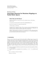
Bit error rate (BER) performance versus the pulse
repetition interval T
r
is shown in Figure 2. Notice that BER
performances become better in both coexisting systems MB-
OFDM and IEEE802.11a WLAN when the pulse repetition
interval is equal to the OFDM IFFT/FFT duration or half that
of the IFFT/FFT. The characteristics of the BER performance
due to changing the pulse repetition interval are the same for
MB-OFDM and IEEE802.11a systems.
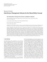
BER performance is also shown for a D/U ratio in the
AWGN channel where E
b
/N
0
is equal to 20 dB in Figure 3.
In the MB-OFDM system, the BER performance is the same
for T
r
= 1nanosecond and T
r
= 10 nanoseconds, that is,
high-duty cycle UWB. The BER performance is improved
by extending the pulse repetition interval. When the pulse
repetition interval equals half the MB-OFDM IFFT/FFT
duration, BER performance becomes better by about 3 dB
over when it is affected by interference from a high-duty cycle
UWB system. The BER deteriorated when interfered with by
T
r
= 200 nanoseconds p-UWB but is 6 dB better in compar-
ison to when interfered with by high-duty cycle UWB with a
repetition interval set to the same length as the MB-OFDM
OFDM IFFT/FFT duration. When the pulse repetition inter-
val is further increased, the BER performance deteriorates
again. The BER performance of the IEEE802.11a WLAN
shows the same characteristics as MB-OFDM when pulse
repetition interval is normalized by the IFFT/FFT duration.
4 EURASIP Journal on Wireless Communications and Networking
Pulse repetition interval (ns)
0 50 100 150 200 250 300
BER
10
−5
10
−4
10
−3
10
−2
10
−1
10
0
D/U = 6dB
D/U
= 3dB
D/U
= 0dB
D/U
=−3dB
D/U
=−6dB
(a) MB-OFDM
Pulse repetition interval (ns)
0 500 1000 1500 2000 2500 3000 3500
BER
10
−5
10
−4
10
−3
10
−2
10
−1
10
0
D/U =−9dB
D/U
=−12 dB
D/U
=−15 dB
D/U
=−18 dB
D/U
=−21 dB
(b) IEEE802.11a
Figure 2: BER performance of OFDM interfered with by p-UWB for changing pulse repetition intervals (E
b
/N
0
= inf.).
D/U (dB)
−10 −8 −6 −4 −20 2 4 6 810
BER
10
−5
10
−4
10
−3
10
−2
10
−1
10
0
T
r
= 1ns
T
r
= 10 ns
T
r
= 100 ns
T
r
= 121 ns
T
r
= 200 ns
T
r
= 242 ns
T
r
= 1000 ns
(a) MB-OFDM
D/U (dB)
−24 −22 −20 −18 −16 −14 −12 −10 −8 −6 −4
BER
10
−5
10
−4
10
−3
10
−2
10
−1
10
0
T
r
= 10 ns
T
r
= 100 ns
T
r
= 1066 ns
T
r
= 1600 ns
T
r
= 2400 ns
T
r
= 3200 ns
T
r
= 4000 ns
(b) IEEE802.11a
Figure 3: BER performance of OFDM interfered with by p-UWB (E
b
/N
0
= 20 dB).
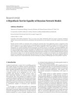
In Figure 4, BER performance is evaluated for a multi-
path channel. The channel model adopted is CM3 as set out
by the IEEE802.15.4a working group [18]. IEEE802.15.4a is a
standard for low-duty cycle PAN systems. Interference prob-
lems often occur when the victim transmitter is very close
to the UWB transmitter. In most of cases, their positions
are in line of sight (LOS). CM3 is designed for office LOS
environments. It is assumed that OFDM receiver channel
estimation and multipath compensation are perfect for the
desired signal. The BER performance improves as the pulse
repetition interval is set as per the proposal. The effectiveness
of the proposed method is clearer for the IEEE802.11a
WLAN system since the symbol duration is longer.
Pulse-based UWB should be transmitted at intervals of
one half or one IFFT/FFT period to take the coexisting
OFDM system into account. In UWB systems, the interfer-
ence problem occurs when a UWB system terminal and a
coexisting system terminal are used at close range, since the
spectrum is extremely spread and has the suppressed the
power spectrum density. The pulse repetition interval should
be adjusted to minimize the effects of the most harmful
coexisted OFDM system.
K. Ohno and T. Ikegami 5
D/U (dB)
−10 −50 5101520
BER
10
−5
10
−4
10
−3
10
−2
10
−1
10
0
T
r
= 1ns
T
r
= 100 ns
T
r
= 121 ns
T
r
= 150 ns
T
r
= 242 ns
T
r
= 1000 ns
(a) MB-OFDM
D/U (dB)
−25 −20 −15 −10 −50
BER
10
−5
10
−4
10
−3
10
−2
10
−1
10
0
T
r
= 10 ns
T
r
= 1000 ns
T
r
= 1600 ns
T
r
= 2400 ns
T
r
= 3200 ns
T
r
= 4000 ns
(b) IEEE802.11a
Figure 4: BER performance of OFDM interfered with by p-UWB in CM3.
3.2. Analysis of the interfering signal in
the OFDM receiver
In this section, a mechanism for determining the pulse
repetition cycle in the proposed interference mitigation
technique is illustrated.
The interfering signal is derived from OFDM signal
demodulation in the receiver. The received interfering UWB
pulse waveform is presumed to be
r(t)
=
∞
i=0
d
i
a
0
δ
t − iT
r
,(5)
where a
0
is the amplitude of the received UWB pulse. The
received UWB interfering signal is passed through a band
pass filter (BPF) for the OFDM signal and is down converted
to the baseband as follows.
Filtering
r
filter
(t) = r(t) ⊗ h
r
(t)exp
j2πf
c
t
=
∞
i=0
d
i
a
0
h
r
t − iT
r
exp
j2πf
l
t − iT
r
.
(6)
Down convert
r
dc
(t)=r
filter
(t)exp
−
j
2πf
c
t + φ
=
∞
i=0
d
i
a
0
h
r
t − iT
r
exp
−
j
2πf
c
iT
r
+ φ
=
∞
i=0
d
i
a
0
h
r
t−iT
r
)
cos
2πf
c
iT
r
+φ
+j sin
2πf
c
iT
r
+φ
,
(7)
where h
r
(t) denotes the impulse response of the BPF in
the baseband. φ is the phase difference and is assumed to
be a random value. The signal is delimited by a window
interval and is converted from analog to digital. Quantization
is ignored here. The signal is sampled at T
FFT
/N. The signal
duration of the filter impulse response is 2
·T
FFT
/N, assuming
that the filter has the same bandwidth as the OFDM signal.
Therefore, the h
r
(t) is represented by one or two sampling
points. Equation (8) shows the signal after analog to digital
conversion (ADC) assuming one sampling point per pulse:
r
filter
(n) =
I−1
i=0
d
i
a
in
cos
2πf
c
iT
r
+ φ
δ
n − n
0
− in
r
−
j sin
2πf
c
iT
r
+ φ
δ
n − n
0
− in
r
,
(8)
where I is the number of pulses in a window interval, that
is, T
FFT
/T
r
. a
in
is amplitude of the each sampling point, n
0
is
the first pulse position in a window interval, and n
r
is pulse
repetition cycle after sampling, thus n
r
= T
r
N/T
FFT
, and is
rounded off to an integer number.
The signal is processed using an FFT:
R
fft
(k)
=
N−1
n=0
r
filter
(n)exp
−
j2π
nk
N
=
I−1
i=0
√
2 d
i
a
in
cos
2πf
c
iT
r
+ φ
cos
2πk
N
n
0
+ in
r
+
π
4
+ j sin
2πf
c
iT
r
+ φ
sin
2πk
N
n
0
+ in
r
+
π
4
.
(9)
6 EURASIP Journal on Wireless Communications and Networking
R
fft
(k)/σ
2
00.511.522.533.54
f
y
(x)(normalizedΣ f
y
(x) = 1)
10
−3
10
−2
10
−1
10
0
T
r
= 1ns
T
r
= 121 ns
T
r
= 242 ns
Gaussian
Tw o s i ne wa ve s
Sine wave
Figure 5: APD of the interfering signal after FFT in the OFDM
receiver.
The real and imaginary parts of the R
fft
(k) interfere with the
In-phase and Quadrature-phase components of the OFDM
demodulation, respectively. Therefore, the interfering sig-
nal’s contribution to the OFDM demapping can be expressed
as the sum of sinusoidal waves. The number of sinusoidal
waves is the number of interfering UWB pulses in a window
interval. The effect of interference depends on the amplitude
probability density (APD) of R
fft
(k). To mitigate the effect
of the interference, the amplitude of the interfering signal
should be constant. Conversely, if the R
fft
(k) has high-peak
amplitude, like Gaussian distribution, the BER performance
of the victim system deteriorates.
When the pulse repetition interval is equal to the OFDM
IFFT/FFT duration, the effect of interference is approximated
as interference from a sinusoidal wave. The normalized APD
variation of the sinusoidal wave is expressed as (10)[19]. The
APD of R
fft
(k) depends a great deal on the BER performance
of the OFDM signal:
f
y
(x) =
⎧
⎪
⎨
⎪
⎩
1
π
√
1 − x
2
/2
|
x| <
√
2
,
0
|
x|≥
√
2
.
(10)
Figure 5 shows the APD of R
fft
(k) including only the
interferer. Here, the OFDM signal is assumed to be a MB-
OFDM, and the band is fixed to avoid frequency hopping to
the same band as the p-UWB signal. The p-UWB waveform
is the same as Section 3.1 and is shown in (4). The pulse
width is 1 nanosecond. The APD, where T
r
equals T
FFT
,is
almost the same as the APD of a sinusoidal wave shown in
(10).
The effect on interference of increasing the number of
interfering pulses can be approximated to a Gaussian distri-
bution by the central limit theorem. The APD is also con-
firmed to correspond to a Gaussian distribution in Figure 5
when the pulse repetition interval equals 1 nanosecond.
When the pulse repetition interval is equal to half the
IFFT/FFT duration, the number of pulses in a window
interval I becomes two, and real part of the R
fft
(k)isderived
thus
Re
R
fft
(k)
=
d
0
a
0n
cos(φ)cos
2πkn
0
N
+
π
4
+d
1
a
1n
cos
πf
l
T
FFT
+φ
cos
2πkn
0
N
+ πk+
π
4
.
(11)
Equation (12) can be separated into two cases where k is
either even or odd, since the phase difference between the
first and second terms is kπ.
k
= even number
Re
R
fft
(k)
=
d
0
a
0n
cos(φ)+d
1
a
1n
cos
πf
l
T
FFT
+ φ
×
cos
2πkn
0
N
+
π
4
=
A
even
cos
2πkn
0
N
+
π
4
,
(12)
k
= odd number
Re
R
fft
(k)
=
d
0
a
0n
cos(φ) − d
1
a
1n
cos
πf
l
T
FFT
+ φ
cos
2πkn
0
N
+
π
4
=
A
odd
cos
2πkn
0
N
+
π
4
.
(13)
To simplify the equation, A
even
and A
odd
are set as per (12)
and (13), respectively.
Normalized APD of the interfering signal is expressed as
the sum of two sinusoidal wave distributions as follows:
f
y
(x) =
f
y,even
(x)+ f
y,odd
(x)
2
, (14)
f
y,even
(x) =
⎧
⎪
⎪
⎨
⎪
⎪
⎩
1
π
1 −
x/A
even
2
|
x| <A
even
,
0
|x|≥A
even
.
(15)
f
y,odd
(x) is expressed in the same way as A
odd
in (16). f
y
(x)is
normalized so that total power as 1. Thus
1
2
A
odd
2
2
+
A
even
2
2
=
1. (16)
Therefore, the maximum amplitude of R
fft
(k) becomes two
in the worst case, when either A
even
or A
odd
is equal to zero.
a
0n
and a
1n
become the same when the total number of
subcarriers in the OFDM is an even number. For the MB-
OFDM system, cos(φ)andcos(πf
c
T
FFT
+ φ) become the
K. Ohno and T. Ikegami 7
D
sym
/U
filter
(dB)
02468101214
BER
10
−5
10
−4
10
−3
10
−2
10
−1
10
0
T
r
= 1ns
T
r
= 121 ns
T
r
= 200 ns
T
r
= 242 ns
Gaussian (theory)
T
r
= 121 ns (theory)
T
r
= 200 ns (theory)
T
r
= 242 ns (theory)
Figure 6: BER performance of OFDM signal compared to theoret-
ical values.
same, since f
c
is set multiple to 264 MHz (= 528/2), and
T
FFT
is N/528 MHz. The system operates a 528 MHz-based
oscillator to reduce the hardware structure. d
i
is modulated
to
±1. Thus, A
even
or A
odd
is equal to zero, and the APD of
the interfering signal in the MB-OFDM receiver is expressed:
f
y
(x) =
⎧
⎪
⎪
⎪
⎪
⎪
⎪
⎪
⎪
⎨
⎪
⎪
⎪
⎪
⎪
⎪
⎪
⎪
⎩
1
2π
√
1 − x
2
/4
|
x| < 2, x
/
=0
,
2
x
i
=−2
1
2π
1 − x
2
i
/4
+
1
2π
(x
= 0),
0
|
x|≥2
.
(17)
The distribution also corresponds to the simulation results
when the pulse repetition interval is 121 nanoseconds in
Figure 5. The derivation is accurate, though the pulse
waveform is assumed to have an impulse shape, and sampling
points are omitted in ADC.
The BER performance for the OFDM interfered with by
the p-UWB is calculated from the APD of the interfering
signal. The D/U ratio is redefined as D
sym
/U
filter
here to
compare the simulation and theory. The desired signal power
D
sym
is the average power per symbol duration (excluding
the cyclic prefix duration). The undesired signal power U
filter
is defined as the average power over time after the signal
is passed through the BPF in the OFDM receiver and does
not depend on the pulse waveform under the assumption
that UWB bandwidth is wider than the OFDM system. The
BER performance of OFDM interfered with by p-UWB is
expressed in (18) when the number of the interfering pulses
I can be considered large:
BER
gauss
D
sym
U
filter
=
1
2
erfc
D
sym
2U
filter
. (18)
The APD of the interference is assumed to be a Gaussian
distribution. Thus, (18) is the same as the formula for BER
performance by coherent detection in an AWGN channel.
Equations (19)and(20) show BER performance in which the
pulse repetition interval is the same as and half the OFDM
IFFT/FFT duration, respectively:
T
r
= T
FFT
(I = 1)
BER
|I=1
D
sym
U
filter
=
∞
√
D
sym
/2U
filter
f
y
(x)dx
=
⎧
⎪
⎪
⎪
⎪
⎨
⎪
⎪
⎪
⎪
⎩
1
2
−
1
π
arcsin
D
sym
2U
filter
D
sym
2U
filter
< 1
,
0
D
sym
2U
filter
≥ 1
,
(19)
T
r
= T
FFT
/2
BER
|T
r
=T
FFT
/2
D
sym
U
filter
=
⎧
⎪
⎪
⎪
⎪
⎨
⎪
⎪
⎪
⎪
⎩
1
4
−
1
2π
arcsin
D
sym
4U
filter
D
sym
4U
filter
< 1
,
0
D
sym
4U
filter
≥ 1
.
(20)
The BER of a signal interfered with by a sinusoidal wave
is derived from the probability distribution function shown
in (10)[19]. When the pulse repetition interval is half the
IFFT/FFT period, the error rate converges by 1/4, because the
interfering signal becomes zero at 1/2 probability from (17).
Theoretical and simulated BER performances are shown
in Figure 6. Coexisting pulse UWB and MB-OFDM
are simulated, and performance when the pulse repeti-
tion interval equals 1 nanosecond, 121 nanoseconds, and
242 nanoseconds corresponds to the theoretical values.
Therefore, the number of interfering pulses in a window
interval should be reduced to mitigate the effect of p-UWB
interference on OFDM.
BER performance was investigated for varying numbers
of interfering UWB pulses in each window interval as the
IFFT/FFT duration cannot necessarily be a multiple of the
pulse repetition interval. The number of UWB pulses in a
window interval can fall into either of two cases: I
0
and I
0
+1,
since the pulse repetition cycle is constant. I
0
has a smaller
number of pulses in a window interval. The probability of
the number of interfering pulses is expressed:
I
= I
0
P
b,I
0
=
(I
0
+1)T
r
− T
FFT
T
r
, (21)
8 EURASIP Journal on Wireless Communications and Networking
OFDM
(MB-OFDM)
DS-UWB
to mitigate
ahalfof
sub-carriers
(Eq. 26)
DS-UWB
to reduce peak
power ratio
(Eq. 27)
T
FFT
IFFT/FFT period
GI
CP
T
c
= T
FFT
/2 T
r
= MT
c
T
c
= T
FFT
/2
Symbol
Symbol
t
t
t
Figure 7: Time frames of proposed DS-UWB.
I = I
0
+1
P
b,I
0
+1
=
T
FFT
− I
0
T
r
T
r
. (22)
The undesired power in each window interval also differs
from the undesired power defined as the average across the
duration U:
I
= I
0
U
I
0
=
I
0
T
r
T
FFT
·U, (23)
I
= I
0
+1
U
I
0
+1
=
I
0
+1
T
r
T
FFT
·U, (24)
and BER performance is expressed:
BER
D
sym
U
filter
=
P
b,I
0
BER
|I=I
0
D
sym
U
filter
·
T
FFT
I
0
T
r
+ P
b,I
0
+1
BER
|I=I
0
+1
D
sym
U
filter
·
T
FFT
I
0
+1
T
r
.
(25)
The BER performance worsens because the interfering power
is increased in the second term of (25). To mitigate the
effect of the interference, the probability of the rebeing large
numbers of interfering pulses P
b,I
0
+1
should be reduced to
a satisfactory level or the undesired power in any window
interval U
I
0
+1
should to be close to the average power U.For
this purpose, it is necessary that T
FFT
= I
0
T
r
or T
FFT
= (I
0
+
1)T
r
from (22)and(24), respectively. Therefore, the number
of interfering UWB pulses in a window interval should be
constant over time to mitigate the effect of the interference.
For example, the BER performance of the MB-OFDM
interfered with by the p-UWB is derived when T
r
is equal
to 200 nanoseconds. The number of UWB pulses in each
window interval is one or two. The probabilities of a single
pulse P
b,1
and two pulses P
b,2
occurring in a given window
are 0.21 and 0.79, respectively. The BER is calculated from
(19) when I
= 1. When the number of interfering pulses is
two, and the pulse repetition interval is not half the symbol
duration, the BER must be derived from the APD of the
interfering signal R
fft
(k). The interfering signal is the sum of
two sinusoidal waves. Therefore, the APD is expressed as the
convolution of the APD of the sinusoidal wave from (10).
The BER performance is derived by integrating the APD and
(19). The BER performance for T
r
= 200 nanoseconds can
be calculated using (25). BER performance is illustrated in
Figure 6 and is almost identical to the simulated result. The
performance is worse than for pulse repetition intervals equal
to, and half of, the IFFT/FFT period.
There are, therefore, two main aspects of the proposed
interference mitigation technique: the APD of the interfering
signal after FFT process in the OFDM receiver and varying
the interfering power for the window interval. To reduce
high-peak amplitude of interfering signal, the number
of interfering pulses in any window interval should be
minimized to regulate the pulse repetition interval.
In conventional UWB systems, the pulse repetition
cycle is decided from the p-UWB system requirements.
Thus, in most cases, a shorter-pulse repetition interval is
chosen without considering the effects of interference. Pulse
repetition intervals effective in mitigating the effects of
interference for the OFDM signal are investigated. When
K. Ohno and T. Ikegami 9
interfering signals exist in the UWB allocated band, the pulse
repetition interval should be adjusted to IFFT/FFT duration
of OFDM system.
4. A TECHNIQUE FOR THE MITIGATION OF
DS-UWB INTERFERENCE ON OFDM
In this section, an interference mitigation technique focused
on pulse repetition cycle is applied to direct sequence
(DS)-UWB. Spreading codes and chip repetition cycles are
proposed to mitigate the interference effects in OFDM
subcarriers and to reduce the peak power of UWB signals.
4.1. Interference mitigation for individual subcarriers
To protect individual OFDM subcarriers, UWB pulse coding
patterns and pulse repetition intervals are proposed. Impor-
tant information can be transmitted on OFDM subcarriers
resistant to interference from UWB signals.
When the pulse repetition interval is half the IFFT/FFT
duration, in MB-OFDM and IEEE802.11a systems ( f
c
=
5.18–5.32 GHz), half of the subcarriers is not interfered with
as per (17). If there are two interfering UWB pulses in a
window interval that are modulated with the same codes,
that is, [+1 +1] or [
−1 −1], even numbered subcarriers
are not interfered with. Odd numbered subcarriers are not
interfered with, if the pulses are modulated with different
codes, that is, [+1
−1] or [+1 −1].
If UWB is encoded as DS-UWB, the spreading codes are
all either the same ([+1 +1]) or alternating ([+1
−1]). The
proposed UWB signal is expressed:
s
uwb
(t) =
∞
i=0
M
−1
m=0
d
i
c
m
·s
0
t −
mT
FFT
2
−
iMT
FFT
2
, (26)
where M is the length of the spreading codes, c
m
is the
spreading code, and m is mth chip. The pulse repetition
interval is constant at half the IFFT/FFT period of the
OFDM. An example DS-UWB time frame is shown in
Figure 7.
Simulation results are presented in Figure 8. The MB-
OFDM parameter is used as the OFDM signal. The UWB
pulse is the same as that in (4). When all codes are
alike([+1+1]or[+1+1+1+1+1+1+1+1]),the
effects of interference on the even numbered subcarriers
are improved when compared to the subcarriers in p-
UWB. The mitigation effects are better, when the spreading
code is longer, because the probability of two UWB pulses
modulated by the same codes falling in the same window
interval is increased; the error rate becomes 1/M better than
ordinary p-UWB. However, the BER of the odd numbered
subcarriers deteriorates by 2
− 1/M, since the average BER is
the same as for p-UWB. When the spreading code contains
alternating codes like [+1
−1] or [+1 −1+1−1+1−1
+1
−1], the performance of the odd numbered subcarriers
improves greatly. The error rate is the same as for the even
numbered subcarriers using the same codes.
The total BER performance of the even subband pulses
and the odd subband pulses is the same as the performance
D/U (dB)
−10 −8 −6 −4 −20 2 4 6 810
BER
10
−5
10
−4
10
−3
10
−2
10
−1
10
0
[+1 + 1] even subcarriers
[+1 + 1] odd subcarriers
[+1
− 1] even subcarriers
[+1
− 1] odd subcarriers
[+1+1+1+1+1+1+1+1]even
[+1+1+1+1+1+1+1+1]odd
[+1
− 1+1−1+1− 1+1− 1] even
[+1
− 1+1−1+1− 1+1− 1] odd
Figure 8: BER performance of OFDM for even and odd numbered
subcarriers interfered with by DS-UWB.
of uncoded p-UWB. However, it is important to protect
individual subcarriers from UWB interference. Total BER
performance is also better than for that interfered with by
high-data rate p-UWB, because the pulse repetition interval
is set to half the OFDM IFFT/FFT duration.
4.2. Using DS-UWB to reduce the peak power of UWB
UWB transmitting power is defined both as average power
over a period sufficient for measurement, and the peak
power output, by most regulations. Extending the pulse
repetition interval should reduce UWB transmitting power
as measured according to various regulations. Here, the
UWB signal is spread as DS-UWB, and the symbol repetition
cycle is controlled to mitigate the effects of interference. The
DS-UWB is expressed:
s
uwb
(t) =
∞
i=0
M
−1
m=0
d
i
c
m
·s
0
t − mT
c
− iT
r
, (27)
where T
c
denotes the chip repetition cycle, which is set to
match the UWB pulse width. An example of DS-UWB time
frame is illustrated in Figure 7.
Figure 9 shows BER performance versus the symbol
repetition cycle of DS-UWB. DS-UWB is spread over 8 and
64 chips, the spreading codes are M-sequence (maximum
length sequence) and add “+1” to set the code length.
The OFDM signal used is a MB-OFDM PAN system. The
bandwidth of the MB-OFDM signal is wider than the gap
that exists in the DS-UWB spectrum depending on the
10 EURASIP Journal on Wireless Communications and Networking
Symbol repetition interval (ns)
0 50 100 150 200 250 300
BER
10
−4
10
−3
10
−2
10
−1
D/U
= 6dB
D/U
= 9dB
D/U
= 6dB
D/U
= 3dB
D/U
= 0dB
D/U
=−3dB
(a) 8 chip spreading code
Symbol repetition interval (ns)
50 100 150 200 250 300
BER
10
−4
10
−3
10
−2
10
−1
D/U
= 6dB
D/U
= 3dB
D/U
= 0dB
D/U
=−3dB
(b) 64 chip spreading code
Figure 9: BER performance of OFDM signal interfered with by DS-UWB for changing symbol repetition intervals (T
c
= 1 nanosecond).
D/U (dB)
−10 −8 −6 −4 −20 2 4 6 810
BER
10
−5
10
−4
10
−3
10
−2
10
−1
10
0
T
r
= 8ns
T
r
= 121 ns
T
r
= 200 ns
T
r
= 242 ns
(a) 8 chip spreading code
D/U (dB)
−10 −8 −6 −4 −20 2 4 6 810
BER
10
−5
10
−4
10
−3
10
−2
10
−1
10
0
T
r
= 8ns
T
r
= 121 ns
T
r
= 200 ns
T
r
= 242 ns
(b) 64 chip spreading codes
Figure 10: BER performance of OFDM interfered with by DS-UWB (E
b
/N
0
= 20 dB).
spreading codes. The characteristics of the BER performance
are almost the same as Figure 2(a). When the symbol
repetition interval is equal to or half of the OFDM IFFT/FFT
period, the BER performance improves the same extent as
the p-UWB paired with an OFDM signal.
In Figure 10, the BER performance is evaluated by chang-
ing the D/U ratio. The improvement in the BER performance
drops as spreading code length increases, because the symbol
duration of DS-UWB is also extended. In (8), the number
of sampling points for each pulse is assumed to be one since
the impulse response duration of the BPF is short. However,
the number of sampling points for each symbol becomes
larger than for p-UWB. Thus, the sinusoidal wave in (9)is
also increased to extend symbol duration, and the effect of
the interference becomes closer to a Gaussian distribution.
Therefore, it is important that the symbol duration of DS-
UWB should be shorter, and the symbol repetition interval
should be set to equal to or half of the OFDM IFFT/FFT
duration.
5. CONCLUSION
In this paper, an interference mitigation technique is
proposed to set a pulse repetition cycle that does not
K. Ohno and T. Ikegami 11
reduce UWB average signal power. Coexistence issues among
pulse-based UWB and OFDM signals are discussed. When
the pulse repetition interval is set to the same as or
half the OFDM IFFT/FFT duration, BER performance of
the OFDM signal improves. Thus, it is important when
deciding the pulse repetition interval for coexisting OFDM
system parameters. This interference mitigation technique is
expanded for DS-UWB systems. An explanation of how the
symbol repetition interval in DS-UWB can be set to mitigate
interference with individual subcarriers and to reduce the
UWB peak power is provided.
The proposed interference mitigation techniques relate
only to control the pulse repetition interval. This provides
the advantage that they can be implemented in relatively
simple UWB transmitter/receiver structures. Therefore, the
system is suitable for simple hardware and low-data rate
UWB systems.
REFERENCES
[1] M. Z. Win and R. A. Scholtz, “Ultra-wide bandwidth time-
hopping spread-spectrum impulse radio for wireless multiple-
access communications,” IEEE Transactions on Communica-
tions, vol. 48, no. 4, pp. 679–691, 2000.
[2] FCCET Docket 98–153, “FIRST REPORT AND ORDER:
Revision of Part 15 of the Commission’s Rules Regarding
Ultra-Wideband Transmission Systems,” February 2002.
[3] Ministry of internal Affairs Communications, “The report of
UWB radio system group,” February 2005.
[4] Electronic Communications Committee, “ECC Decision of 1
Dec. 2006 on the harmonized conditions for devices using
UWB technology with Low Duty Cycle in the frequency band
3.4GHz–4.8GHz,” CEPT, December 2006.
[5] A. Tomiki, I. Pasya, and T. Kobayashi, “Simulation of interfer-
ence effects from MB-OFDM and DS-UWB to a QPSK digital
transmission system,” IEICE Transactions on Fundamentals of
Electronics, Communications and Computer Sciences, vol. E89-
A, no. 11, pp. 3059–3065, 2006.
[6] M. Hamalainen, J. Saloranta, J P. Makela, I. Oppermann, and
T. Patana, “UWB impact on IEEE802.11b wireless local area
network,” in Proceedings of the 6th International Symposium on
Wireless Personal Multimedia Communications (WPMC ’03),
pp. 278–282, Yokosuka, Japan, October 2003.
[7] S. Choi, S. Cho, and H. Lee, “UWB interference test in
IEEE802.11b WLAN environment,” in Proceedings of the
International Workshop on Ultra Wideband Systems (IWUWBS
’03), Oulu, Finland, June 2003.
[8] H. Yamaguchi, “Active interference cancellation technique for
MB-OFDM cognitive radio,” in Proceedings of the 34th Euro-
pean Microwave Conference, vol. 2, pp. 1105–1108, London,
UK, October 2004.
[9] H. Zhang and R. Kohno, “Re-configurable soft-spectrum
UWB receiving scheme with multi-mode and multi-rate
adaptation,” in Proceedings of the 6th International Symposium
on Wireless Personal Multimedia Communications (WPMC
’03), Yokosuka, Japan, October 2003.
[10]H.Zhang,X.Zhou,K.Y.Yazdandoost,andI.Chlamtac,
“Multiple signal waveforms adaptation in cognitive ultra-
wideband radio evolution,” IEEE Journal on Selected Areas in
Communications, vol. 24, no. 4, pp. 878–884, 2006.
[11] K. Ohno and T. Ikegami, “Interference mitigation study
for UWB radio using template waveform processing,” IEEE
Transactions on Microwave Theory and Techniques, vol. 54,
no. 4, pp. 1782–1792, 2006.
[12] K. Ohno and T. Ikegami, “Interference detection and miti-
gation by using multi-carrier template wave for pulse based
UWB,” in Proceedings of the 9th IEEE International Symposium
on Spread Spectrum Techniques and Application (ISSSTA ’06),
pp. 183–187, Manaus, Brazil, August 2006.
[13] K. Ohno and T. Ikegami, “Interference DAA technique for
coexisting UWB radio,” in Proceedings of the 65th Vehicular
Technology Conference (VTC ’07), pp. 2910–2914, Dublin,
Ireland, April 2007.
[14] R. van Nee, OFDM for Wireless Multimedia Communications,
Artech House, London, UK, 1999.
[15] A. Batra, “Multi-band OFDM Physical Layer Proposal,”
IEEE802.15-03/267r6, September 2003.
[16] A. Batra, “Physical Layer Submission to 802.15 Task Group 3a:
Multi-band OFDM,” IEEE802.15-03/268r3, March 2004.
[17] IEEE, “Part 11: Wireless LAN Medium Access Control (MAC)
and Physical Layer (PHY) specifications: High-speed Physical
Layer in the 5 GHZ Band,” IEEE Std 802.11a-1999, September
1999.
[18] A. F. Molisch, et al., “IEEE 802.15.4a channel model final
report,” IEEE P802.15-04/662r0-SG4a, November 2004.
[19] A. Papulis, Probability, Random Variables, and Stochastic
Process, McGraw-Hill, New York, NY, USA, 1965.