Báo cáo hóa học: "Research Article OV-CDMA System: Concept and Implementation" potx
Bạn đang xem bản rút gọn của tài liệu. Xem và tải ngay bản đầy đủ của tài liệu tại đây (900.63 KB, 9 trang )
Hindawi Publishing Corporation
EURASIP Journal on Wireless Communications and Networking
Volume 2008, Article ID 460628, 9 pages
doi:10.1155/2008/460628
Research Article
OV-CDMA System: Concept and Implementation
Elie Inaty and Rafic Ayoubi
Department of Computer Engineering, Faculty of Engineering, University of Balamand, P.O. Box 100,
Deir El-Balamand, El-Koura, Lebanon
Correspondence should be addressed to Elie Inaty,
Received 7 September 2007; Revised 5 December 2007; Accepted 25 January 2008
Recommended by Stefan Kaiser
A new method is proposed to achieve a multirate overlapped code division multiple access system (OV-CDMA) based on a novel
code overlapping procedure. The signal-to-interference ratio (SIR) performance has been investigated for such system. A channel
model that allows multirate overlapped transmission is presented based on which a closed form solution for the SIR has been
derived. In addition, a simple yet very efficient block diagram of the transmitter and the receiver architecture has been proposed
for such a system. Based on the proposed block diagram, the encoder-decoder has been implemented using an FPGA. Numerical
results show that the newly proposed OV-CDMA scheme outperforms the classical variable processing gain fast frequency hopping
CDMA (VPG-FFH-CDMA) for different system scenarios. Finally, real-time measurements have been successfully obtained using
a hardware prototype utilizing the simple Xilinx Spartan IIE (XC2S200E) FPGA.
Copyright © 2008 E. Inaty and R. Ayoubi. This is an open access article distributed under the Creative Commons Attribution
License, which permits unrestricted use, distribution, and reproduction in any medium, provided the original work is properly
cited.
1. INTRODUCTION
During the past few years, there has been a growing interest
in the development of broadband wireless communication
networks for multimedia applications. The communication
services in such networks can be high- and low-speed data,
video, and many others with different performance and
trafficrequirements[1–3].
Classical fast frequency hopping CDMA (FFH-CDMA)
has been discussed in many works [4–6]. A multirate FFH-
CDMA system using variable processing gain (PG) (VPG-
FFH-CDMA) has been proposed in [3, 7, 8]. The intention
was to guarantee the one-to-one correspondence between
the PG and the source transmission rate. The drawback of
this system is the drastic decrease in the transmitted signal
power especially for higher rate users for which the PG
becomes very small. The solution to this problem is the use
of power control [9]; on the other hand, Kwong and Yang
in [7, 8] considered the multilength frequency hopping
codes. Using these codes, rate and QoS are now dynamically
matched to users’ needs. The cutoff rate of the system is still
limited by the physical constraints of the codes.
In this work, the general problem we considered is how
much we can increase the transmission rates of different
classes of traffic beyond the nominal permitted rates. Our
aim is to optimize performance to meet the quality of service
(QoS)requirementsgivenafixednumberofusersinthe
network and a multimedia distribution. For an op-timized
family of codes, we will show that it is possible to increase a
class bit rate beyond the nominal rate without decreasing the
PG of the desired user or allowing any time delay between the
data symbols. Our system achieves a multirate transmission
by introducing an overlap between the transmitted symbols,
hence the name overlapped code division multiple access
system (OV-CDMA). In addition, we will consider the im-
plementation of the OV-CDMA system [10]. The control
unit of the transmitter and the receiver has been accom-
plished using FPGA. A pipeline technique is used to achieve
a high-computational efficiency. A prototype is built and
tested. We have been able to achieve a transmission rate
ranging from 0.1 to 20 Mbps. It is imperative to mention
that the five-channel case implemented in this paper can be
easily modified to higher number of channels. This is the
main advantage of FPGA [11].
The paper is organized as follows. In Section 2,we
present the OV-CDMA encoding/decoding technique.
Section 3 derives the performance of the OV-CDMA system.
Section 4 describes the OV-CDMA system implementation
2 EURASIP Journal on Wireless Communications and Networking
where the block diagrams of the transmitter and the receiver
are presented and discussed. In addition, the hardware im-
plementation using FPGA is discussed in Section 5. Section 6
contains the numerical results and the measurements. Fi-
nally, the conclusion is presented in Section 7.
2. OV-CDMA SYSTEM MODEL
Consider a multirate OV-CDMA communication system
that supports M users in N different classes, which share the
same medium [10]. The corresponding PGs for each class are
given by G
0
>G
1
> ··· >G
N−1
. The nominal bit duration
is given by T
s
= G
s
T
c
with T
c
being the chip duration. The
corresponding nominal rate is R
n s
= 1/T
s
. When the data
rate increases beyond R
n s
, multibits can be coded during
the time period T
s
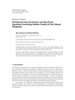
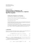
and transmitted together as revealed in
Figure 1. In this figure, the PG is G
s
= 5, which means that
five channels are used in the coding process. When user k
transmits using rate R
s
>R
n s
, it introduces a bit overlap
coefficient ε
s
according to which the new rate is related to
the nominal rate through the following:
R
s
=
G
s
G
s
− ε
s
R
n s
. (1)
In Figure 1, the overlapping coefficient is ε
s
= 3; therefore,
the new transmission rate is R
s
= (5/2)R
n s
. This means that
the new transmission rate is 2.5 times the transmission rate
without overlap. At a given receiver, the decoder observes
practically multicode which is delayed according to the
transmission rate of the source as shown in Figure 1.
In this paper, we assume the following: (1) a chip and bit
synchronous system and a discrete rate variation, (2) all users
in the class-s, s
∈{0, 1, , N − 1} have the same bit overlap
coefficient 0
≤ ε
s
<G
s
− 1;thuseachclassischaracterizedby
(G
s
, ε
s
), and (3) a unit transmission power for all the users.
2.1. Signal structure
We d efine a
(s)
k
(t, f )andb
(s)
k
(t) as the hopping pattern and
the baseband signal, respectively, where t and f represent
the time and frequency dimensions. From Figure 1, the bit
stream can be seen to be serial-to-parallel converted to v
pulses. Assuming that the desired user is using the class-
m, which is characterized by a PG G
m
and an overlapping
coefficient ε
m
. Since the desired user nominal time period
is T
m
= G
m
T
c
, we are interested only in modeling the k th
interfering channel during a time period T
m
. Because the
bit b
k
X
from the v-bitsisdelayedbyτ
X
= X(G
s
− ε
s
)T
c
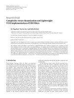
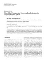
,
this suggests that the channel model, as seen by the desired
receiver, can be represented as a tapped delay line with tap
spacing of τ
−1
=−(G
s
− ε
s
)T
c
from left and τ
1
= (G
s
−
ε
s
)T
c
from right. The tap weight coefficients b
k
X
∈{−1, 1}
depending on whether the transmitted bit is zero or one.
The truncated tapped delay line model as seen by the desired
receiver is shown in Figure 2. Accordingly, the transmitted
signal is given by
S
k
(t, f ) =
v
b
k
v
a
(s)
k
t − τ
v
, f
. (2)
b
k
−2
f
k
0
f
k
1
f
k
2
f
k
3
f
k
4
τ
−2
b
k
−1
f
k
0
f
k
1
f
k
2
f
k
3
f
k
4
τ
−1
ε
s
= 3
b
k
0
f
k
0
f
k
1
f
k
2
f
k
3
f
k
4
f
k
0
f
k
1
f
k
2
f
k
3
f
k
4
τ
1
b
k
1
f
k
0
f
k
1
f
k
2
f
k
3
f
k
4
τ
2
b
k
2
Figure 1: Coding method of the proposed OV-CDMA system with
G
s
= 5andε
s
= 3.
a
(s)
k
(t, f )
τ
−1
τ
−1
τ
1
τ
1
b
k
X
r
b
k
1
b
k
0
b
k
−1
b
k
−X
1
Wireless
channel
Receiver
y(t, f )s
k
(t, f )
Σ
Figure 2: OV-CDMA channel model.
Lemma 1. Given an interferer k with (G
s
, ε
s
) and the desired
user with (G
m
, ε
m
) for alls, m ∈{0,1, , N − 1}. At the de-
sired receiver end, during the nominal t ime period T
m
, the ob-
served total number of taps in channel k is given by
N
k
G
m
, G
s
, ε
s
=
ε
s
G
s
− ε
s
+
ΔG + ε
s
G
s
− ε
s
+1, (3)
where ΔG
= G
m
− G
s
.
Lemma 2. Given an interferer k with (G
s
, ε
s
) and the desired
user with (G
m
, ε
m
), the observed total number of transmitted
codes from transmitter k that undergo a total overlap with the
desired correlator during T
m
and excluding the normal bit b
k
0
is
given by
X
t
=
|
ΔG|
G
s
− ε
s
,(4)
where
x is the highest integer smaller than x and |ΔG| is
given by
|ΔG|=
⎧
⎨
⎩
G
m
− G
s
, if G
m
>G
s
,
G
s
− G
m
, if G
m
≤ G
s
.
(5)
The received signal at the input of the decoder is therefore
given by
y(t, f )
= n(t)+
M−1
k=0
X
r
v=−X
l
b
k
v
a
(s)
k
t − τ
v
, f
,(6)
where n (t) is an additive white Gaussian noise (AWGN) with
two-sided power spectral density Γ
0
/2.
E. Inaty and R. Ayoubi 3
2.2. Decoder’s output
Without loss of generality, we assume that the correlation-
matched filter is matched to the zeroth signal with class-m.
The output of the matched filter correlator will be
Z
(m)
0
= Γ +
T
m
0
M
−1
k=0
S
k
t − τ
v
, f
a
(m)
0
(t, f ) dt,(7)
where Γ is a zero-mean AWGN with variance σ
2
n
= ΓT
m
/4.
The multiple access interference (MAI) I
k
from user k that
transmits data with rate R
s
can be written as
I
k
=
−1
v=−X
l
τ
v
0
b
k
v
h
a
(s)
k
t − τ
v
, a
(m)
0
(t)
dt
+
X
t
v=0
τ
v
+T
s
τ
v
b
k
v
h
a
(s)
k
t − τ
v
, a
(m)
0
(t)
dt
+
X
r
v=X
t
+1
T
m
τ
v
b
k
v
h
a
(s)
k
t − τ
v
, a
(m)
0
(t)
dt, G
m
>G
s
,
I
k
=
1−X
t
v=−X
l
τ
v
0
b
k
v
h
a
(s)
k
t − τ
v
, a
(m)
0
(t)
dt
+
0
v=−X
t
T
m
0
b
k
v
h
a
(s)
k
t − τ
v
, a
(m)
0
(t)
dt
+
X
r
v=1
T
m
τ
v
b
k
v
h
a
(s)
k
t − τ
v
, a
(m)
0
(t)
dt, G
m
≤ G
s
,
(8)
for all k
/
= 0. h(·) is the Hamming function [10]. The sequen-
ces a
(s)
k
(t)anda
(m)
0
(t) are numbers representing frequencies
used at time t for the kth interferer and the desired user,
respectively. Notice that a
(s)
k
(i) = a
(s)
k
(i + T
s
). In addition,
we define a new performance parameter called the auto-
interference I
0
caused by the desired user’s signal and it is
given by
I
0
=
−1
v=−X
r
τ
v
0
b
0
v
h
a
(m)
0
t − τ
v
, a
(m)
0
(t)
dt
+
X
r
v=1
T
m
τ
v
b
0
v
h
a
(m)
0
t − τ
v
, a
(m)
0
(t)
dt.
(9)
3. OV-CDMA PERFORMANCE EVALUATION
Since the user may set a connection for a particular multi-
media class and modify it dynamically, the index s is a dis-
crete random variable with a certain prior probability
p
(i)
k
= Pr(user k chooses class-i)
= Pr(s = i) ∀ i ∈{0, 1, , N − 1}
(10)
with
N−1
s
=0
p
(s)
k
= 1andwecallp
(s)
k
the multimedia probabil-
ity mass function (pmf) for user k. I
k
,forall0≤ k ≤ M − 1,
is assumed to be an independent random variable. Hence the
variance of the decision variable Z
(m)
0
is
var
Z
(m)
0
=
M−1
k=1
N
−1
s=0
p
(s)
k
σ
2
I
k
/s
+ σ
2
I
0
+ σ
2
n
, (11)
σ
2
I
k
/s
and σ
2
I
0
represent the interference power caused by an
active user k using class-s and the auto-interference power
caused by the desired user due to overlapping, respectively,
and they are given by
σ
2
I
k
/s
= E
I
2
k
s
−
E
2
I
k
s
,
σ
2
I
0
= E
I
2
0
−
E
2
I
0
,
(12)
where E(
·) is the expectation operator over all possible values
of the overlapping bits b
k
X
for X ∈{−X
l
, , X
r
} assuming
that Pr(b
k
X
= 1) = Pr(b
k
X
=−1) = 1/2. E(I
k
/s) and the cross
terms generated from squaring the summation in E(I
2
k
/s)
become zeros because the average over the bit is zero, which
enables us to write
E
I
2
k
s
=
R
k
T
m
, T
s
, ε
s
=
⎧
⎪
⎪
⎪
⎪
⎪
⎪
⎪
⎪
⎪
⎪
⎪
⎪
⎪
⎪
⎪
⎪
⎪
⎪
⎨
⎪
⎪
⎪
⎪
⎪
⎪
⎪
⎪
⎪
⎪
⎪
⎪
⎪
⎪
⎪
⎪
⎪
⎪
⎩
1
2
−1
v=−X
l
H
2
k,0
0, τ
v
+
X
t
v=0
H
2
k,0
τ
v
, τ
v
+ T
s
+
X
r
v=X
t
+1
H
2
k,0
τ
v
, T
m
, G
m
>G
s
,
1
2
1−X
t
v=−X
l
H
2
k,0
0, τ
v
+
0
v=−X
t
H
2
k,0
0, T
m
+
X
r
v=1
H
2
k,0
τ
v
, T
m
, G
m
≤ G
s
,
(13)
E
I
2
0
= R
0
T
m
, ε
m
=
1
2
−1
v=−X
r
H
2
0,0
0, τ
v
+
X
r
v=1
H
2
0,0
τ
v
, T
m
,
(14)
where
H
k,0
τ
i
, τ
j
=
τ
j
τ
i
h
a
k
t − τ
v
, a
0
(t)
dt. (15)
Let q
v
= τ
v
/T
c
,wecanwrite
H
k,0
0, τ
v
= T
c
H
v
0, q
v
= T
c
q
v
−1
j=0
h
a
k
j
−q
v
, a
0
j
,
H
k,0
τ
v
, T
m
= T
c
H
v
q
v
, G
m
= T
c
G
m
−1
j=q
v
h
a
k
j
−q
v
, a
0
j
,
H
k,0
τ
v
, τ
v
+ T
s
=
T
c
H
v
q
v
, q
v
+G
s
=
T
c
q
v
+G
s
−1
j=q
v
h
a
k
j
−q
v
, a
0
j
.
(16)
4 EURASIP Journal on Wireless Communications and Networking
If we define R
k
(G
m
, G
s
, ε
s
)=R
k
(T
m
, T
s
, ε
s
)/(T
2
c
/2) and R
0
(G
m
,
ε
m
) = R
0
(T
m
, ε
m
)/(T
2
c
/2), then we substitute into (12), the
SIR experienced by any active user that uses class-m is
SIR
m
=
α
2
G
2
m
M−1
k
=1
N−1
s
=0
p
(s)
k
R
k
G
m
, G
s
, ε
s
+R
0
G
m
, ε
m
+σ
2
n
,
(17)
where α is a random variable with a Rayleigh distribution
assuming a Rayleigh fading channel. Thus the distribution of
α
2
is exponential [12].
3.1. Effective increase in the number of hits
Proposition 1. For one-coincidence sequences with nonrepeat-
ing frequencies [13, 14], the expected value of the increase in
the number of hits caused by any active interferer with (G
s
, ε
s
)
on a desired user with (G
m
, ε
m
) is given by (19). In addition,
the effective increase of the number of hits due to the auto-
interference is
I
0
H
G
m
, ε
m
=
0, (18)
where X
r
, X
l
, X
t
,and|ΔG| are given throughout Lemmas 1 and
2, and F is the total number of available frequencies,
I
k
H
G
m
, G
s
, ε
s
=
1
F
G
s
−
G
s
−ε
s
2
X
l
−
G
s
−ε
s
2
X
2
l
+
G
m
−
G
s
−ε
s
2
X
r
−
G
s
−ε
s
2
X
2
r
+
G
s
−ε
s
2
−|ΔG|
X
t
+
G
s
−ε
s
2
X
2
t
.
(19)
3.2. Average SIR
Assuming that the overlapping codes are independent virtual
active users and one-coincidence sequences, we can compute
the average correlations given in (13). In addition, if we
assume that the multimedia pmf is the same for every user,
p
(s)
k
= p
(s)
, the average SIR for the desired user with (G
m
, ε
m
)
will be
SIR
m
=
α
2
G
2
m
(M − 1)/2
β + σ
2
n
,
(20)
where β
={
N−1
s
=0
([p
(s)
·G
s
]/F)+
N−1
s
=0
[p
(s)
·I
k
H
(G
m
, G
s
, ε
s
)]}.
In (20), we have been able to separate the interference power
into the normal MAI power caused by active users when R
s
=
R
n s
and the one caused by virtual users that overlap with the
desired user’s code when R
s
>R
n s
.
4. OV-CDMA SYSTEM IMPLEMENTATION
Throughout this paper, and without loss of generality, the
analysis is based on the five-channel example presented
in Figure 1. The problem of designing a transmitter that
performs the overlapping operation is simplified to find a
0
5
10
15
20
25
30
SIR (dB)
00.10.20.30.40.50.60.70.80.91
OV-CDMA
VPG-FFH-CDMA
M = 10
M
= 20
M
= 10
M
=
20
Normalized transmission rate
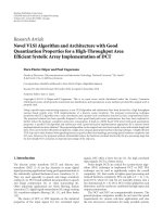
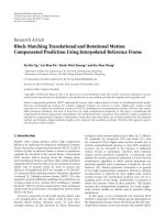
Figure 3: Average SIR versus the normalized transmission rate.
way to transmit more that one frequency channels during the
same chip period T
c
as shown in Figure 1.
4.1. OV-CDMA transmitter implementation
For example, during the first period T
c
, the transmitter
should send channels f
k
0
, f
k
2
,andf
k
4
at the same time.
Classical FFH-CDMA transmitters use what is widely known
as frequency synthesizer to generate one carrier frequency at
each T
c
seconds. It cannot generate multifrequency at the
same time. For this reason, we propose a new architecture
based on multifrequency generators and a switching opera-
tion that is performed by a central processing unit as revealed
by Figure 4(a). The control unit will determine the switches
which must be closed and the other which should be open.
The result is summed and transmitted. This task can be
easily accomplished using the desired user’s code as shown
in Figure 4(b). The above five-by-five matrix of binary data
represents the digital control code that must be used by the
control unit for the five-channel example shown in Figure 1.
Note that during the first chip duration, the switches are
controlled by the first row of the matrix such that S
1
, S
3
,
and S
5
are closed, and S
2
and S
4
are open. This enables us
to transmit simultaneously channels f
k
0
, f
k
2
,and f
k
4
. This
matrix will be repeated every bit duration T
n
.
4.2. OV-CDMA receiver implementation
The receiver should first perform the decoding operation of
the overlapped code then decide whether the transmitted bit
is zero or one. The block diagram of the receiver is shown
in Figure 5. It is composed of two major parts: the analog
part and the digital part using FPGA. In the analog circuitry
part, the incoming radio frequency signal is detected using
the CDM2502 antenna. The incoming electric signal is
subdivided into five channels with equal power. Then, for
every channel, a bandpass filter (BPF) is used with a center
E. Inaty and R. Ayoubi 5
f
k
0
f
k
1
f
k
2
f
k
3
f
k
4
S
1
S
2
S
3
S
4
S
5
Control unit
User’s code sequence
Data bit stream b
∈{0, 1}
(a)
1
0
1
0
1
0
1
0
1
0
1
0
1
0
1
0
1
0
1
0
1
0
1
0
1
T
c
T
n
(b)
Figure 4: (a) Five-channel OV-CDMA transmitter, (b) OV-CDMA digital control unit.
T
c
0
||
2
dt
T
c
0
||
2
dt
T
c
0
||
2
dt
T
c
0
||
2
dt
T
c
0
||
2
dt
E
1,1
0
E
3,1
0
E
5,1
0
E
2,2
0
E
4,2
0
E
1,3
0
E
3,3
0
E
5,3
0
E
2,4
0
E
4,4
0
E
1,5
0
E
3,5
0
E
5,5
BPF
f
0
BPF
f
1
BPF
f
2
BPF
f
3
BPF
f
4
tT
c
Splitter
Reset
every T
c
sec
Sum the
elements of the
5
× 5matrixevery
5T
c
(s)
Comparison
with a
threshold
0
1
Figure 5: Five-channel OV-CDMA receiver.
frequency f
k
i
, which is one of the employed channels by the
desired user. An energy detector (ED) is used to measure the
energy of the filtered signal. An analog-to-digital converter
(ADC) is utilized in order to convert the analog information
from the ED into digital one so that it can be accepted by the
FPGA logic.
It is imperative to mention that we will use the same
code logic used in the encoder side. This code replica is
used to dispread the received signal and to obtain the
transmitted data stream. The outputs of the ADCs are held
inside the registers then shifted to the right at every time
period T
c
. After five consecutive cycles, a 5 × 5matrixis
constructed. The contents of this matrix are added, then
the result is compared to a predefined detection threshold.
The compared data is the energy added after five consecutive
cycles. If the result is less than the threshold, it is estimated
that 0 is transmitted; otherwise, it is judged that 1 is sent.
5. DIGITAL IMPLEMENTATION USING FPGA
After data is received, it is digitally processed using FPGA
technology. The target FPGA family is a Xilinx Spartan IIE
(XC2S200E) due to the availability of boards based on this
family in our labs. In order to achieve high performance, pi-
pelining technique was used. A block diagram of the FPGA
implementation is shown in Figure 6. Even though the figure
shows an example of eight channels, only five channels were
implemented in hardware. However, our implementation
can be generalized to any number of channels.
6 EURASIP Journal on Wireless Communications and Networking
M-I
M-I
M-I
M-I
M-I
M-I
M-I
Counter FSM
Load
Reset
Serial
adder
ACC
16-bit shift
register
>
Comparator
with a
threshold
<
Output
bit
= “1”
Output
bit
= “0”
16-bit shift
register
Serial
adder
16-bit shift
register
16-bit shift
register
Module-I (M-I)
ADC 1
ADC 2
ADC 3
ADC 4
ADC 5
ADC 6
ADC 7
ADC 8
Figure 6: Logic block diagram of the decoder and the decision of the receiver.
Name
Va lu e
3.2
clk
ADC1
ADC2
ADC3
ADC4
ADC5
Idata
Start
Output
U0
U0
U0
U0
U0
U0
U0
U0
U0U0
200
0
221
0
250
0
200
0
200
0
250
0
220
0
200
0
220
0
200
0
200
200
250
0
0
0
0
0
200
220
250
0
250
0
250
0
220
0
250
0
200
0
200
0
250
0
250
200
200
170 ns 800 ns 1.6 μs2.4 μs
0 ps 320 ns 640ns 960 ns 1.28 μs1.6 μs1.92 μs2.24 μs2.5
μs
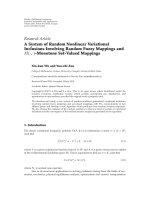
Figure 7: Simulated timing diagram.
For an N-channel receiver, an N × N addition is required
every bit period T
n
,whichiscomposedofN chip periods T
c
;
in addition, each T
c
seconds is composed of 16-bit stream.
The addition is performed in a tree fashion (see Figure 6).
Therefore, it takes log
2
(N)cyclestosumN numbers (N
channels). Since we need N
× N addition, the summation
should be performed N times; that is Nlog
2
(N) cycles.
However, by using pipelining technique, we were able to
reduce the number of cycles for an N
× N addition to
log
2
(N)+(N − 1).
This high-speed implementation is achieved at the
expense of N
−1 adders. In order to reduce the area occupied
by the design, serial adders were used. Even though the
summation of 16-by-16 bits requires 16 cycles, the clock fre-
quency achieved is several times higher than that of a parallel
adder.
As an example, consider an 8-channel receiver (Figure 6).
Every chip period T
c
eight 8-bit ADCs convert the received
analog signals into eight bits, which are extended into 16
bits and shifted serially into eight 16-bit shift registers. The
serial outputs from every two shift registers are fed into a
serial adder, which will perform the summation and generate
the sum of one bit at a time. The output of each adder is
connected to the input of another 16-bit shift register in
order to store the results of the summation. Each module
(M-I) in Figure 6 corresponds to two shift registers at the
input of an adder and another shift register connected to the
output of the adder.
For thiseight channels example, the proposed implemen-
tation consists of a three-stage pipeline that performs the
addition in a tree fashion. After initially filling the pipeline
stages (this requires 3 clock cycles), all pipeline stages will
be performing similar tasks. For instance, every clock cycle,
Stage 1 would be performing four summations on the newly
received data from the ADCs, whereas Stage 2 would be
doing two parallel summations on the already summed data
E. Inaty and R. Ayoubi 7
Table 1: Implementation results.
Number of slices 138 out of 2352 5%
Number of slice flip flops 232 out of 4704 4%
Number of 4 input LUTs 86 out of 4704 1%
Max. clock frequency 100.675 MHz
from Stage 1 that corresponds to the older ADC conversion.
At the same time, Stage 3 would be summing the results
from Stage 2 of the previous data. After eight clock cycles,
an output bit is generated based on a threshold comparison,
and the accumulator register is cleared in order to start
accumulating data for a new output bit. This process is
repeated after each eight clock cycles.
Ta bl e 1 summarizes the mapping results in terms of lo-
gical resources and maximal clock period on a Xilinx Spartan
IIE XC2S200E speed grade-7 FPGA. As shown in Tab le 1,for
our 5-channel receiver, the utilization of the FPGA chip did
not exceed 5%, which means that we can easily upgrade our
design into cases including larger number of channels on the
same Spartan IIE used. Moreover, the clock period achieved
was less than 10 nanoseconds.
6. NUMERICAL RESULTS AND MEASURMENTS
For the purpose of comparing the performance of our newly
proposed OV-CDMA system with existing multirate systems,
Figure 3 shows the SIR comparison between the OV-CDMA
and the classical VPG-FFH-CDMA systems while varying
the transmission rate. The transmission rate is normalized
in the sense that it begins by zero when ε
s
= 0 for the
OV-CDMA system and when G
s
= 40 for the VPG FFH-
CDMA system. The normalized transmission rate increases
by increasing ε
s
or decreasing G
s
for the OV-CDMA and
the VPG-FFH-CDMA, respectively. Notice that, for either
M
= 10 or M = 20 users, the SIR for the OV-CDMA system
is always greater than that of the VPG-FFH-CDMA system.
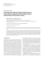
In Figure 7, we present the simulated timing diagram for
the OV-CDMA receiver in which the input signals ADC1,
ADC2, ADC3, ADC4, and ADC5 to the FPGA are coming
from the ADCs. This simulation is performed for an over-
lapping coefficient ε
s
= 3. Each input is composed of eight
parallel bits. Each output bit lasts for the whole period of five
data reception, after which the new bit is output based on
the last five data reception. The optimal detection threshold
is obtained using the maximum likelihood detection scheme.
After comparison with the threshold, the decision for the
possible transmitted symbol is shown in Output.
The test bed has been implemented using an educational
FPGA board which is the Xilinx Spartan IIE XC2S200E speed
grade-7. In addition, the setup includes a wireless local area
network antenna of type CDM2502 working in the 2.4-
2.5 GHz band. Using this test bed, we have been able to trans-
mit and receive a digital signal successfully. Figures 8(a) and
8(c) show the transmitted and the corresponding measured
received information signals, respectively, in the presence of
three interferers and using the five channels encoder-decoder
presented previously. The results show clearly that the
0246810121416 19
010 0
Input waveform
(a)
00.02 0.04 0.06 0.08 0.1
−4
−2
0
2
4
Tr an sm it te d wav e
Amplitude
Time
(b)
0246810121416 19
010 0
Output waveform
(c)
Figure 8: Measured signals: (a) binary input wave, (b) OV-CDMA
coded signal, and (c) binary-decoded wave.
three transmitted bits are received successfully. In addition,
Figure 8(b) is the measured OV-CDMA coded transmitted
signal of the desired user.
Using the test bed built in our labs, we have been able
to measure the SIR and the bit error rate (BER) of our
proposed system. An experiment has been conducted using a
very high number of coded bits using our technique. Figure 9
8 EURASIP Journal on Wireless Communications and Networking
0 5 10 15 20 25 30 35 40
5
10
15
20
25
SIR (dB)
ε
s
= overlapping coefficient, M = 20
Measured
Analytical
Figure 9: System’s SIR (in dB) versus the overlapping coefficient
using real measurements and the analytical results obtained in (20).
1234567 8
Number of active users
10
−6
10
−5
10
−4
10
−3
10
−2
10
−1
Measured BER
Figure 10: Measured bit error rate.
shows the measured SIR and the simulated one using the
derivedequationin(17) versus the overlapping coefficient.
We assume 20 active terminals. It is clear that there is a total
agreement between the measured and the analytical results.
On the other hand, using a transmission rate of 10 Mbits/s,
Figure 10 presents measured BER versus the total number
of active simultaneous users in the network. It is clear that
our system guarantees a good performance in the presence
of MAI.
7. CONCLUSION
In this paper, we have proposed a simple technique yet
very efficient to implement a multirate/multiclass CDMA
system based on a novel code overlapping procedure. A
system model was presented and the SIR was derived. The
block diagram of the transmitter and the receiver were
presented and discussed. Moreover, an efficient FPGA-based
transceiver implementation was shown. This implementa-
tion was efficient in terms of both speed and area. Using
simple educational FPGA board of type Xilinx Spartan
IIE (XC2S200E), the measurement results showed that the
proposed system can achieve very good performance in
the presence of MAI. Both simulation and measurements
showed that it is possible to increase the transmission
rate well beyond the nominal rate. On the other hand,
simulation results reveal that our newly proposed OV-
CDMA outperform the classical VPG-FFH-CDMA.
ACKNOWLEDGMENTS
This paper was presented in part at the IEEE VTC 2004 and
IEEE ISCAS 2006 conferences. This work was supported in
part by the Lebanese CNRS under Grant CNRSL no. 4082.
REFERENCES
[1] T. D. C. Little and A. Ghafoor, “Network considerations for
distributed multimedia object composition and communica-
tion,” IEEE Network, vol. 4, no. 6, pp. 32–40, 1990.
[2] T. Ottosson and A. Svensson, “Multi-rate performance in
DS/CDMA system,” Tech. Rep. 14, Department of Informa-
tion Theory, Chalmers University of Technology, G
¨
oteborg,
Sweden, March 1995.
[3] R. Wyrmas, W. Zhang, M. J. Miller, and R. Anjaria, “Multiple
access options for multimedia wireless systems,” in Proceedings
of the 3rd Workshop on third Generation, pp. 289–294,
Manchester, UK, April 1992.
[4] E. Geraniotis, “Multiple-access capability of frequency-
hopped spread-spectrum revisited: an analysis of the effect of
unequal power levels,” IEEE Transactions on Communications,
vol. 38, no. 7, pp. 1066–1077, 1990.
[5]M.V.HegdeandW.E.Stark,“Ontheerrorprobability
of coded frequency-hopped spread-spectrum multiple-access
systems,” IEEE Transactions on Communications,vol.38,no.5,
pp. 571–573, 1990.
[6] S. Maric, “Construction of optimal frequency hopping
sequences for minimizing bit errors in selective fading chan-
nels characteristic to digital cellular systems,” IEE Proceedings
Communications, vol. 142, no. 4, pp. 271–273, 1995.
[7] W. C. Kwong and G C. Yang, “Frequency-hopping codes
for multimedia services in mobile telecommunications,” IEEE
Transactions on Vehicular Technology, vol. 48, no. 6, pp. 1906–
1915, 1999.
[8] W. C. Kwong and G C. Yang, “New frequency-hopping codes
for multimedia mobile communication systems,” in Proceed-
ings of the IEEE Pacific Rim Conference on Communications,
Computers and Signal Processing (PACRIM ’99), pp. 329–332,
Victoria, BC, Canada, August 1999.
[9] P. Liu, P. Zhang, S. Jordan, and M. L. Honig, “Single-
cell forward link power allocation using pricing in wireless
networks,” IEEE Transactions on Wireless Communications,
vol. 3, no. 2, pp. 533–543, 2004.
[10] E. Inaty and C. Ghostine, “Overlapped FFH-CDMA and
variable processing gain FFH-CDMA: performance evaluation
and comparison,” in Proceedings of the 59th IEEE Vehicular
Technology Conference (VTC ’04), vol. 3, pp. 1436–1440,
Milan, Italy, May 2004.
E. Inaty and R. Ayoubi 9
[11] E. Inaty and R. Ayoubi, “FPGA-based transmitter-receiver
architecture of an overlapped CDMA system: design and sim-
ulation,” in Proceedings of the IEEE International Symposium
on Circuits and Systems (ISCAS ’06), pp. 2797–2800, Kos
island, Greece, May 2006.
[12] T. Rappaport, Wireless Communications, Principles and Prac-
tice, Prentice Hall PTR, Upper Saddle River, NJ, USA, 2002.
[13] L. D. Wronski, R. Hossain, and A. Albicki, “Extended
hyperbolic congruential frequency hop code: generation and
bounds for cross- and auto-ambiguity function,” IEEE Trans-
actions on Communications, vol. 44, no. 3, pp. 301–305, 1996.
[14] L. Bin, “One-coincidence sequences with specified distance
between adjacent symbols for frequency-hopping multiple
access,” IEEE Transactions on Communications, vol. 45, no. 4,
pp. 408–410, 1997.