Báo cáo hóa học: " Research Article Minimum BER Receiver Filters with Block Memory for Uplink DS-CDMA Systems" pdf
Bạn đang xem bản rút gọn của tài liệu. Xem và tải ngay bản đầy đủ của tài liệu tại đây (881.07 KB, 12 trang )
Hindawi Publishing Corporation
EURASIP Journal on Wireless Communications and Networking
Volume 2008, Article ID 462710, 12 pages
doi:10.1155/2008/462710
Research Article
Minimum BER Receiver Filters with Block Memory for
Uplink DS-CDMA Systems
Are Hjørungnes
1
and M
´
erouane Debbah
2
1
UNIK - University Graduate Center, University of Oslo, Instituttveien 25, P.O. Box 70, 2027 Kjeller, Norway
2
Alcatel-Lucent Chair on Flexible Radio,
´
Ecole Sup
´
erieure d’
´
Electricit
´
e, Plateau de Moulon, 3 Rue Joliot-Curie,
91192 Gif-sur-Yvette Cedex, France
Correspondence should be addressed to Are Hjørungnes,
Received 24 September 2007; Revised 28 January 2008; Accepted 10 March 2008
Recommended by Tongtong Li
The problem of synchronous multiuser receiver design in the case of direct-sequence single-antenna code division multiple access
(DS-CDMA) uplink networks is studied over frequency selective fading channels. An exact expression for the bit error rate (BER)
is derived in the case of BPSK signaling. Moreover, an algorithm is proposed for finding the finite impulse response (FIR) receiver
filters with block memory such that the exact BER of the active users is minimized. Several properties of the minimum BER
FIR filters with block memory are identified. The algorithm performance is found for scenarios with different channel qualities,
spreading code lengths, receiver block memory size, near-far effects, and channel mismatch. For the BPSK constellation, the
proposed FIR receiver structure with block memory has significant better BER with respect to E
b
/N
0
and near-far resistance than
the corresponding minimum mean square error (MMSE) filters with block memory.
Copyright © 2008 A. Hjørungnes and M. Debbah. This is an open access article distributed under the Creative Commons
Attribution License, which permits unrestricted use, distribution, and reproduction in any medium, provided the original work is
properly cited.
1. INTRODUCTION
CDMA is a multiple access technique where the user sepa-
ration is done neither in frequency, nor in time, but rather
through the use of codes. However, the frequency selective
fading channel destroys in many cases the codes separation
capability and equalization is needed at the receiver. Since
the beginning of the nineties, multiuser detection [1–
3] has provided multiuser receivers with different perfor-
mance/complexity tradeoffs. Usual target metrics concern
either maximizing the likelihood, the spectral efficiency, or
minimizing the mean square error. In many cases, analytical
expressions of the multiuser receivers performance can be
obtained which depend mainly on the noise structure, the
channel impulse response, the nature of the codes, and the
receiver parameters [4–7].
In the present work, minimum BER is used as a target
metric for designing the DS-CDMA FIR receiver filters for
BPSK signaling, where the receiver has one FIR multiple-
input single-output (MISO) filter with block memory for
each user. It is assumed that the system is synchronized.
Various works (see, e.g., [8–10]), have minimized BER with
respect to the receiver parameters in a perfect synchronized
system when the receiver is modeled by a memoryless block
receiver filter. In [11], they have studied minimum BER
receiver filter for single-user SISO systems and no transmitter
filter was considered. An adaptive algorithm for finding
minimum BER filters without block memory in the receiver
filters was proposed in [12]. The case of receiver filters with
block memory of a DS-CDMA system has been studied
for blind equalization in [13], and the problem of CDMA
receiver design has also been studied in [14], however, the
problem of minimum BER receiver filter design for multiuser
CDMA systems has to the best of our knowledge not been
treated in the literature for communication over frequency
selective channels.
In this contribution, a general framework based on the
discrete-time equivalent low-pass representation of signals is
provided. In particular, (i) exact BER expressions are derived
for an uplink multiuser DS-CDMA system using FIR receiver
filters with block memory; (ii) the significant performance
improvements achieved using receiver filters with block
memory are assessed; (iii) an iterative numerical algorithm
is proposed based on the BER expression for finding the
2 EURASIP Journal on Wireless Communications and Networking
complex-valued minimum BER FIR MISO receiver filters
with block memory, for given spreading codes and known
channel impulse responses. Note that the additive noise on
the channel is complex-valued and it might be colored.
Finally, (iv) several properties of the minimum BER filters
with block memory are identified.
The rest of this paper is organized as follows. Section 2
introduces the DS-CDMA model and formulates the
DS-CDMA receiver optimization problem mathematically.
Section 3 presents the proposed solution, and Section 4 sum-
marizes the proposed numerical optimization algorithm.
In Section 5, numerical results obtained with the proposed
algorithm are presented and comparisons are made against
the MMSE receiver with block memory. Conclusions are
drawn in Section 6. Finally, three appendices contain proofs
and tools used in the article throughout.
2. DS-CDMA MODEL
2.1. Special notations
In this contribution, receiver filters with finite block memory
are used in a DS-CDMA system for communication over
frequency selective FIR channels. For helping the reader to
keep track of the special notations, Ta bl e 1 summarizes the
most important quantities used in this paper, and gives the
size of these symbols. The special notation is introduced
in order to solve the FIR DS-CDMA receiver filter design
problem in a compact manner when the filters have finite
block memory.
In this article, all the indexing begins with 0. Let A(z)
=
η
i
=0
A(i)z
−i
be an FIR MIMO filter of order η and size
M
0
× M
1
, such that the block memory of the filter is η.The
matrix A(i) is the ith coefficient (note that the argument
indicates wheather the matrix is in the time domain A(i)orin
the Z-domain A(z). We want to consequently use uppercase
bold symbols for matrices and lowercase boldface symbols
for vectors, and that is the reason why we have chosen this
convention.) of the FIR MIMO filter A(z) and it has size
M
0
× M
1
.Therow-expanded matrix A
−
obtained from the
FIR MIMO filter A(z)isanM
0
× (η +1)M
1
matrix given by
A
−
= [A(0), A(1), ,A(η)].
Let q be a nonnegative integer. The row-diagonal-
expanded matrix A
(q)
of the FIR MIMO filter A(z)oforderq
is a (q +1)M
0
×(η + q +1)M
1
block Toeplitz matrix given by:
A
(q)
=
⎡
⎢
⎢
⎢
⎣
A(0) ··· A(η) ··· 0
.
.
.
.
.
.
.
.
.
.
.
.
.
.
.
0A(0)
··· ··· A(η)
⎤
⎥
⎥
⎥
⎦
. (1)
Let ν be a nonnegative integer. The symbol n is used as
a time index in this article and n is an integer. Let y(n)be
a vector time-series of size M
× 1. The column expansion of
y(n)oforderν has size (ν+1)M
×1 and is defined as y(n)
(ν)
|
=
[y
T
(n), y
T
(n − 1), ,y
T
(n − ν)]
T
, where the operator (·)
T
denotes transposition.
w
i
M × 1
s
i
(n)
Order 0 x
i
(n)
x
i
(n)
↑ M
↑ M
.
.
.
↑ M
z
−1
z
−1
z
−1
.
.
.
(a)
r
i
(z)
1
×M
y(n)
Order l
y(n)
ˆ
s
i
(n)
↓ M
↓ M
.
.
.
↓ M
z
z
z
.
.
.
ˇ
s
i
(n)
DEC(
·)
(b)
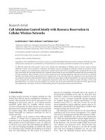
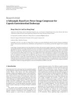
Figure 1: (a) DS-CDMA transmitter number i. (b) DS-CDMA
receiver part designed for decoding user number i.
2.2. Transmission model for user number i
Let the number of users be N. It is assumed that the sequence
of equally likely BPSK information bits s
i
(n) ∈{−1, 1} sent
by user number i
∈{0, 1, , N − 1} is an independent
and identically distributed time-series, uncorrelated with the
additive channel noise and the data sequences sent by the
other users. s
i
(n) are spread with a spreading code having
spreading factor M. Let the vector w
i
be an M × 1vector
containing the spreading code for user number i.Thevector
w
i
is an FIR single-input multiple-output (SIMO) filter
without block memory that increases the sampling rate of
the original signal by the factor M. It is assumed that the
receiver knows the values of all the vectors w
i
, and they can
be chosen arbitrarily, that is, w
i
∈ C
M×1
,whereC denotes
the set of complex numbers, such that any complex-valued
(or real-valued) spreading code might be used. Figure 1(a)
shows the ith transmitter of the DS-CDMA system and the
DS-CDMA receiver part that is designed to decode user
number i is shown by Figure 1(b).InFigure 1, z
−1
is the
delay element, z is the advance element,
↑M is expansion
with factor M meaning that M
−1 zeros are inserted between
each sample, and
↓M is decimation by M;see[15]. The
input sequence x
i
(n) to the ith channel, see Figure 1(a),is
stacked into an M
× 1vectorx
i
(n) according to x
i
(n) =
[x
i
(Mn),x
i
(Mn +1), , x
i
(Mn + M −1)]
T
. The spreading
operation may be written as x
i
(n) = w
i
s
i
(n). In order to
produce the M
×1vectory(n) from a scalar time-series y(n),
see Figure 1(b), the following blocking structure is used:
y(n)
= [y(nM), y(nM +1), , y(nM + M −1)]
T
.
A. Hjørungnes and M. Debbah 3
Let p be a nonnegative integer. Using the previously
introduced notations, the (p +1)M
× 1vectorx
i
(n)
(p)
|
can
be expressed as x
i
(n)
(p)
|
= w
i
(p)
s
i
(n)
(p)
|
, where (note that
boldface is not used for the symbol s
i
(n)
(p)
|
, since this is
interpreted as column-expansion operator working on the
scalar time-series s
i
(n); see also the notation introduced
in Section 2.1) w
i
(p)
= I
p+1
⊗ w
i
has size (p +1)M ×
(p +1),where I
p+1
represents the (p +1)× (p +1)
identity matrix,
⊗ is the Kronecker product, and s
i
(n)
(p)
|
=
[s
i
(n), s
i
(n − 1), ,s
i
(n − p)]
T
has size (p +1)×1.
The ith user has the following scalar multipath channel
transfer function: H
i
(z) =
L
k
=0
h
i
(k)z
−k
. The maximum
order of all N channels is L. It is assumed that L
≤ M. When
L
≤ M, it is shown in [16] that the equivalent FIR MIMO
channel filter C
i
(z)ofsizeM × M has order q = 1, when
the blocking and unblocking operations in Figure 1 are used.
C
i
(z)isgivenbyC
i
(z) = C
i
(0) + C
i
(1)z
−1
, where the two
matrix channel coefficients are given by
C
i
(0) =
⎛
⎜
⎜
⎜
⎜
⎜
⎜
⎜
⎜
⎜
⎜
⎜
⎝
h
i
(0) 0 0 ··· 0
.
.
. h
i
(0) 0 ··· 0
h
i
(L) ···
.
.
.
···
.
.
.
.
.
.
.
.
.
···
.
.
.
0
0
··· h
i
(L) ··· h
i
(0)
⎞
⎟
⎟
⎟
⎟
⎟
⎟
⎟
⎟
⎟
⎟
⎟
⎠
,
C
i
(1) =
⎛
⎜
⎜
⎜
⎜
⎜
⎜
⎜
⎜
⎜
⎜
⎜
⎝
0 ··· h
i
(L) ··· h
i
(1)
.
.
.
.
.
.
0
.
.
.
.
.
.
0
···
.
.
.
··· h
i
(L)
.
.
.
.
.
.
.
.
.
.
.
.
.
.
.
0
··· 0 ··· 0
⎞
⎟
⎟
⎟
⎟
⎟
⎟
⎟
⎟
⎟
⎟
⎟
⎠
.
(2)
The channel is assumed to be corrupted by zero-
mean additive Gaussian complex-valued circularly symmet-
ric noise, denoted by v(n), which is independent of the
transmitted signals. The additive channel noise vector v(n)
of size M
× 1 can be expressed as v(n) = [v(Mn), v(Mn +
1), , v(Mn + M
− 1)]
T
. The channel noise is assumed
to have known second-order statistics, which might be
colored in general. The autocorrelation matrix of size (l +
1)M
× (l +1)M of the (l +1)M × 1vectorv(n)
(l)
|
is
defined as Φ
(l,M)
v
E
v(n)
(l)
|
v(n)
(l)
|
H
, where the operator
(
·)
H
denotes conjugate transpose. Let the variance of the
components of the complex-valued Gaussian circularly
symmetric additive channel noise v(n)begivenbyN
0
=
1/M Tr{Φ
(0,M)
v
},whereTr{·} is the trace operator. N
0
and
Φ
(l,M)
v
are assumed to be known in the receiver. The average
energy per bit E
b
at the input of the channels is given by
E
b
= 1/N
N−1
i=0
E[x
H
i
(n)x
i
(n)] = 1/N
N−1
i=0
w
H
i
w
i
. Let the
channel condition be defined as the value of the energy per
bit-to-noise ratio (i.e., E
b
/N
0
).
There is one receiver filter for each of the N users.
Receiver filter number i takes the M
× 1 input vector y(n)
and produces a scalar as its output; see Figure 1(b). The size
of the ith receiver filter is 1
×M, and its transfer function r
i
(z)
is given by
r
i
(z) =
l
k=0
r
i
(k)z
−k
,(3)
where r
i
(k), of size 1×M, is the filter coefficient number k of
the receiver filter number i. The block memory l is assumed
to be fixed and known. The developed theory is valid for
any nonnegative number l, and it will be demonstrated in
Section 5 that a significant gain can be achieved by using
filters with memory, that is, l>0, compared to memoryless
filters, that is, l
= 0. The desired signal at the output of
the receiver filter number i is d
i
(n) = s
i
(n − δ), where
δ
∈{0, 1, , l +1} denotes the decision delay, and δ is the
same for all N users. Since uplink is considered, the receiver
is trying to estimate the original information bits from all
of the N users by means of N MISO receiver filters with
block memory. At the output of the MISO receiver filter
r
i
(z), a decision device is used to recover the original data
information bits. The blocks denoted by DEC(
·) estimate
the information bits and its output is denoted by
ˇ
s
i
(n).
These estimates are found by taking the real value of a
complex-valued sequence
s
i
(n) and then a hard decision
is made returning +1 if
s
i
(n) is nonnegative and −1if
s
i
(n) is negative. The used memoryless decisions units are
suboptimal and better performance can be obtained if more
advanced soft decoding techniques are employed.
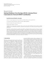
2.3. Block description and input-output relationship
A block description of the whole DS-CDMA system is shown
in Figure 2. All the input signals of the system are assumed to
be jointly wide sense stationary (WSS) (Ta bl e 1 summarizes
the sizes of quantities widely used in this paper).
The row-expanded FIR filter, of size 1
×(l + 2), from the
input of transmitter number i to the output of the receiver
filter number i is given by r
i
−
C
(l)
i
w
(l+1)
i
. The received signal
vector y(n) can be expressed as
y(n)
=
N−1
i=0
C
i
−
w
(1)
i
s
i
(n)
(1)
|
+ v(n). (4)
The vector s
i
(n)
(l+1)
|
has size (l +2)× 1.
Let the (l +2)N
× 1vectors
(i)
(n)bedefinedass
(i)
(n) =
s(n)(s(n))
(l+2)i+δ
= s(n)s
i
(n − δ), where the operator (·)
k
denotes component number k of the vector it is applied to,
and where the vectors s(n)havesize(l +2)N
× 1andare
defined as
s(n)
=
s
0
(n)
(l+1)
|
T
,
s
1
(n)
(l+1)
|
T
, ,
s
N−1
(n)
(l+1)
|
T
T
.
(5)
There exist 2
N(l+2)
different realizations for the vector s(n)
since each component of s(n) is either
−1or+1.Lets
k
(n)
4 EURASIP Journal on Wireless Communications and Networking
Table 1: Symbols, sizes, and descriptions of widely used quantities.
Matrix or vector symbol Size Description
w
i
M ×1 Spreading code for user i
w
i
(ν)
(ν +1)M × (ν + 1) Row-diagonal-expanded spreading code of user i
C
i
(z) M ×M FIR MIMO channel filter for user i
C
i
−
M ×2M Row-expanded channel filter number i
C
(l)
i
(l +1)M × (l +2)M Row-diagonal-expanded channel filter number i
r
i
(z)1×M Receiver filter number i
r
i
−
1 ×(l +1)M Row-expanded receiver filter number i
s
i
(n)1×1 Bits sent from user i
s
i
(n)
(p)
|
(p +1)×1 Column expansion of bits from user i
s
i
(n)1×1 Outputofreceiverfilteri
ˇ
s
i
(n)1×1 Outputofreceiveri after decision
d
i
(n)1×1 Desired output signal of receiver i
s(n), s
k
(n)(l +2)N × 1Different vectors depending on sent bits
s
(i)
k
(n), s
(i)
(n)(l +2)N × 1Different vectors depending on sent bits
y(n) M
×1 Channel output vector
x
i
(n)1×1 ith channel scalar input
x
i
(n) M ×1 ith channel vector input
x
i
(n)
(p)
|
(p +1)M × 1 Column expansion of ith channel vector input
v(n)1
×1 Channel noise sample
v(n) M
×1 Channel noise vector
v(n)
(l)
|
(l +1)M × 1 Column expansion of channel noise
t
(i)
k
(n)
(l)
|
, t
(i)
(n)
(l)
|
(l +1)M × 1 Column expansion of noise-free channel output
Φ
(l,M)
v
(l +1)M × (l +1)M Noise autocorrelation matrix
Order 0
w
0
s
0
(n)
x
0
(n)
Order 0
w
1
x
1
(n)
s
1
(n)
Order 1
C
0
(z)
Order 1
C
1
(z)
Order 0
s
N−1
(n)
w
N−1
x
N−1
(n)
.
.
.
Order 1
C
N−1
(z)
1
×1 M × 1 M × 1 M × MM×11×M 1 ×11×11×1
.
.
.
.
.
.
.
.
.
v(n)
y(n)
Order l
r
0
(z)
ˆ
s
0
(n)
DEC(
·)
ˇ
s
0
(n)
Order l
r
1
(z)
ˆ
s
1
(n)
DEC(
·)
ˇ
s
1
(n)
Order l
r
N−1
(z)
ˆ
s
N−1
(n)
DEC(
·)
ˇ
s
N−1
(n)
Figure 2: Block model of the N users DS-CDMA system.
be one of these vectors s(n), where k ∈{0, 1, ,2
N(l+2)
−
1}, and define the (l +2)N × 1vectors
(i)
k
(n)ass
(i)
k
(n)
s
k
(n)(s
k
(n))
(l+2)i+δ
. Whenever the index k is not required,
s
(i)
(n) might be used to denote one of the s
(i)
k
(n)vectors.
Since (s
k
(n))
k
∈{−1, 1}, the vector s
(i)
(n)willalways
contain+1inthevectorcomponentnumber(l +2)i + δ.
Therefore, there exists a total of
K 2
(l+2)N−1
(6)
different s
(i)
(n)vectors.
The convolution of the zero block memory SIMO filter
w
i
and the first-order MIMO channel transfer function C
i
(z)
is denoted by b
i
(z), and b
i
(z)hassizeM ×1andorder1.The
row expansion of b
i
(z)isgivenbyb
i
−
= C
i
−
w
(1)
i
,andb
i
−
, C
i
−
,
and w
(1)
i
have sizes M ×2, M ×2M,and2M ×2, respectively.
The row-diagonal expansion of b
i
(z)oforderl is given by
b
(l)
i
= C
(l)
i
w
(l+1)
i
,andb
(l)
i
, C
(l)
i
,andw
(l+1)
i
have sizes (l+1)M×
(l +2),(l+1)M ×(l+2)M,and(l +2)M×(l +2), respectively.
Let the matrix T be defined as T [b
(l)
0
, b
(l)
1
, , b
N−1
(l)
],
and it has size (l +1)M
×(l +2)N.
The output of the ith receiver filter at time instance n
is denoted by
s
i
(n) and it is given by s
i
(n) = r
i
−
y(n)
(l)
|
.
It follows from (4) that y(n)
(l)
|
is given by y(n)
(l)
|
=
N−1
k
=0
C
(l)
k
w
(l+1)
k
s
k
(n)
(l+1)
|
+ v(n)
(l)
|
. The overall expression for
the output signal of the receiver filter number i can be written
as
s
i
(n) = r
i
−
Ts(n)+r
i
−
v(n)
(l)
|
. (7)
A. Hjørungnes and M. Debbah 5
2.4. MMSE receiver
The average mean square error (MSE) over all the N users is
defined as MSE
= 1/N
N−1
i=0
MSE
i
, where MSE
i
is the MSE
of the ith user: MSE
i
= E[|s
i
(n) − d
i
(n)|
2
]. It can be shown
that MSE
i
is given by
MSE
i
= r
i
−
Φ
(l,M)
v
r
i
−
H
+1−r
i
Te
(l+2)i+δ
−
e
(l+2)i+δ
H
T
H
r
i
−
H
+ r
i
−
TT
H
r
i
−
H
,
(8)
where e
k
is the unit vector of size (l +2)N × 1with+1in
position number k and zeros elsewhere. By calculating the
derivative with respect to r
∗
i
, where (·)
∗
means complex
conjugation, the MMSE receiver filter (the MMSE filters are
called Wiener filters; see for example [17]) number i is given
by
r
i
−
=
e
(l+2)i+δ
T
T
H
TT
H
+ Φ
(l,M)
v
−1
. (9)
2.5. Definitions
For the DS-CDMA receiver optimization, the following inner
product will be used: for b
i
∈ C
1×(l+1)M
a complex-valued
row vector, then the receiver inner product is defined as
b
0
, b
1
Φ
(l,M)
v
= b
0
Φ
(l,M)
v
b
H
1
. (10)
It can be shown that the following inequality is valid:
Re
b
0
, b
1
Φ
(l,M)
v
≤
b
0
Φ
(l,M)
v
b
1
Φ
(l,M)
v
, (11)
with equality holding if and only if b
0
= βb
1
for an arbitrary
positive constant β.Thereceiver norm is defined by
b
0
Φ
(l,M)
v
=
b
0
, b
0
Φ
(l,M)
v
. (12)
Let Φ
(l,M)
v
= Re{Φ
(l,M)
v
} + jIm{Φ
(l,M)
v
}, where the operators
Re
{·} and Im{·} denote the real and imaginary parts of
the matrix they are applied to and j
=
√
−1 is the
imaginary unit. It can be shown that the real-valued matrix
Re
{Φ
(l,M)
v
} is symmetric and that the real-valued matrix
Im
{Φ
(l,M)
v
} is skew-symmetric. Let also the real matrix Φ ∈
R
2(l+1)M×2(l+1)M
be defined as
Φ
=
⎡
⎣
Re
Φ
(l,M)
v
Im
Φ
(l,M)
v
−
Im
Φ
(l,M)
v
Re
Φ
(l,M)
v
⎤
⎦
. (13)
It can be shown that the matrix Φ is symmetric. Since
Re
b
0
, b
1
Φ
(l,m)
v
=
Re
b
0
Im
b
0
Φ
Re
b
t
1
Im
b
t
1
t
Re
b
0
Im
b
0
,
Re
b
1
Im
b
1
Φ
,
(14)
the value of Re
{b
0
, b
1
Φ
(l,M)
v
} can be interpreted as an inner
product between two vectors in
R
1×2(l+1)M
.
Let the symbol t
(i)
k
(n)
(l)
|
denoting the kth vector of size
(l +1)M
× 1bedefinedast
(i)
k
(n)
(l)
|
Ts
(i)
k
(n). As seen from
the right-hand side of (7), t
(i)
k
(n)
(l)
|
is the column vector
expansion of order l of the noise-free input vector to the
receiver, of size (l +1)M
×1, when the vector s
(i)
k
(n)wassent
from the transmitters. Furthermore, let t
(i)
(n)
(l)
|
= Ts
(i)
(n).
The vector (t
(i)
k
(n)
(l)
|
)
H
[Φ
(l,M)
v
]
−1
has size 1 × (l +1)M,and
thisvectorisnamedareceiver-signal vector.
It is assumed that the system is synchronized such that
the noise-free eye diagrams are in the middle of their
analogue counterparts. The positive part of the ith noise-free
eye diagram at time instant n is defined as the real part of
the noise-free signal at the output of the receiver filter r
i
(z)at
time n when the desired signal is d
i
(n) = s
i
(n−δ) = +1. From
(7)andFigure 2, it can be seen that Re
{r
i
−
Ts
(i)
(n)} is the real
part of the output of the ith MISO receiver filter r
i
(z)attime
n when the vector given by s
(i)
(n) was transmitted with no
channel noise. At time n, the ith receiver filter r
i
−
is trying to
estimate the value of the desired signal d
i
(n) = s
i
(n − δ). In
the vector s
(i)
(n), the value corresponding to s
i
(n−δ)isequal
to +1 due to the definition of s
(i)
(n). The positive part of the
ith noise-free eye diagram can be expressed as
Re
r
i
−
Ts
(i)
k
(n)
=
Re
r
i
−
,
t
(i)
k
(n)
(l)
|
H
Φ
(l,M)
v
−1
Φ
(l,M)
v
,
(15)
where i
∈{0,1, , N − 1} and k ∈{0, 1, , K − 1}. If the
system has an open noise-free eye diagram at the output of
the ith receiver filter, then the expressions in (15)mustbe
positive for all k
∈{0,1, , K −1}.
Definition 1. Let user number i have spreading code of
length M given by w
i
and let the M × M channel block
transfer matrices C
i
(z) be given. These channels are said to be
(l,δ) linear FIR equalizable if there exist N linear FIR MISO
receiver filters r
i
(z) with size 1 × M and block memory l,
see (3), such that all the N noise-free eye diagrams are open
when the delay through the system is δ.
Note that there exist channels that are not linear FIR
equalizable for (l, δ)
= (0, 0), but the same channels might
be linear FIR equalizable for larger values of l or δ.There
exist scalar channels that are not linear FIR equalizable for
some values of N and M, but if these values are sufficiently
increased, then the communication system becomes linear
FIR equalizable.
Definition 1 is similar to [11, Definition 1], where an
equalizable SISO channel for the single user case was defined,
without spreading codes and with no signal expansion, that
is, M
= 1.
Definition 2. The ith receiver -signal set R
i
is defined as
R
i
=
K−1
k=0
g
k
t
(i)
k
(n)
(l)
|
H
Φ
(l,M)
v
−1
g
k
> 0
. (16)
For linear FIR equalizable channels, it is seen from
the equality in (15) that there exists at least one set of
6 EURASIP Journal on Wireless Communications and Networking
receiver filters r
i
−
that has a positive real part of the receiver
inner product with all the receiver-signal vectors. Since the
receiver-signal vectors generate the set R
i
,see(16), the set
R
i
is a cone when the channels are linear FIR equalizable.
The sets in (16)arecalledreceiver-cone, when the channels
are linear FIR equalizable.
In general, for linear FIR equalizable channels, only
subsets of the receiver-signal cones will result in open noise-
free eye diagrams. From (15), it is seen that for linear FIR
equalizable channels, the ith noise-free eye diagram is open
if the following condition is satisfied: the vector r
i
−
lies inside
the subset of R
i
that has a positive real part of receiver inner
product with all the receiver-signal vectors.
Definition 2 is an extension of [11, Definition 2], because
the problem considered there was for SISO single user case
without spreading codes in the transmitters and without
signal expansion, that is, M
= 1. In the above definition,
complex vectors are assumed even though the coefficients g
k
arerealin(16).
If the channel noise is approaching zero for linear FIR
equalizable channels, then it is asymptotically optimal that
all the noise-free eyes are open since this leads to a BER
that approaches zero. All systems operating on equalizable
channels having open noise-free eye diagrams have identical
input and output signals when the original signal is in the set
{−1, +1} and the noise is approaching zero. If the noise level
is increased, then the proposed solution can be applied.
2.6. Exact expression of the BER
The total average BER for the system given in Figure 2 can be
expressed as
BER
=
1
N
N−1
i=0
BER
i
. (17)
BER
i
is the BER of vector component number i of the output
vector
ˇ
s(n) [
ˇ
s
0
(n),
ˇ
s
1
(n), ,
ˇ
s
N−1
(n)]
T
, and it can be
expressed as
BER
i
= Pr
ˇ
s
i
(n)
/
=s
i
(n − δ)
=
Pr
Re
s
i
(n)
s
i
(n − δ) < 0
=
Pr
Re
r
i
−
Ts(n)+r
i
−
v(n)
(l)
|
s
i
(n − δ) < 0
=
Pr
Re
r
i
−
Ts
(i)
(n)+r
i
−
v(n)
(l)
|
s
i
(n − δ)
< 0
=
Pr
−
Re
r
i
−
v(n)
(l)
|
s
i
(n − δ)
> Re
r
i
−
t
(i)
(n)
(l)
|
= E
Pr
−Re
r
i
−
v(n)
(l)
|
s
i
(n − δ)
> Re
r
i
−
t
(i)
(n)
(l)
|
s(n)
,
(18)
where Pr
{·} is the probability operator and Pr{A}=
E
[Pr{A | B}] with the expected value taken with respect to B.
In (18), s
i
(n−δ) = (s (n))
(l+2)i+δ
and the definition of t
(i)
k
(n)
(l)
|
were used. In order to simplify further the expression above,
it is important to realize that the left-hand side of the last
inequality is a real Gaussian stochastic variable with mean
and variance
E
−Re
r
i
−
v(n)
(l)
|
s
i
(n − δ)
=
0,
E
Re
2
r
i
−
v(n)
(l)
|
s
i
(n − δ)
=
1
2
r
i
−
2
Φ
(l,M)
v
,
(19)
where Re
2
{·} denotes the squared value of the real part of
the argument. By utilizing the distribution of the vectors s(n)
and s
(i)
k
(n), the definition of the Q-function together with the
results from (19), it is seen that (18)canberewrittenas
BER
i
= E
⎡
⎣
Q
⎛
⎝
√
2Re
r
i
−
t
(i)
(n)
(l)
|
r
i
−
Φ
(l,M)
v
⎞
⎠
⎤
⎦
=
1
K
K−1
k=0
Q
⎛
⎜
⎜
⎜
⎝
√
2Re
r
i
−
,
t
(i)
k
(n)
(l)
|
H
Φ
(l,M)
v
−1
Φ
(l,M)
v
r
i
−
Φ
(l,M)
v
⎞
⎟
⎟
⎟
⎠
,
(20)
where (15)wasused,andwhereK is given by (6). The
expression for BER is an extension of [9,equation(3)]to
include complex variables and for the case where l>0. For
l
= 0, the expression is also in accordance with [12,equation
(20)], although the expression in [12] contains twice as many
terms for each sum over k. The reason is that in [12], it has
not been considered that the vectors s
(i)
k
(n) contain +1 in
vector component number (l +2)i + δ, independently of k.
Experiments show that there is an excellent match between
the theoretical performance given in (17) and performance
achieved by Monte Carlo simulations.
2.7. Receiver filter normalization and
problem formulation
From (17)and(20), it can be deduced that the exact value of
the BER is independent of the receiver inner product norm
of the vectors r
i
−
. Therefore, there is no loss of optimality by
choosing
r
i
−
2
Φ
(l,M)
v
= r
i
−
Φ
(l,M)
v
r
H
i
−
= 1. (21)
The robust receiver design problem can be therefore formu-
lated as
Ploblem 1: min
{r
0
(z),r
1
(z), ,r
N−1
(z)}
BER. (22)
3. MINIMUM BER RECEIVER FILTER
DESIGN WITH BLOCK MEMORY
3.1. Property of the minimum BER receiver filters
The following lemma states the importance of the receiver-
signal cones when designing optimal receiver MISO filters for
linear FIR equalizable channels.
Lemma 1. If the channels are linear FIR equalizable, then the
minimum BER ith receiver r
i
lies in R
i
.
Proof. The proof of this lemma is given in Appendix A.
A. Hjørungnes and M. Debbah 7
3.2. Numerical optimization algorithm
The necessary conditions for optimality of the ith receiver
filter can be expressed as (∂/∂
∗
r
i
−
)BER = 0
1×(l+1)M
.The
following two conjugate derivatives will be useful:
∂
∂
∗
r
i
−
Re
r
i
−
t
(i)
k
(n)
(l)
|
=
1
2
t
(i)
k
(n)
(l)
|
H
,
∂
∂
∗
r
i
−
1
r
i
−
Φ
(l,M)
v
=
−
1
2
r
i
−
3
Φ
(l,M)
v
r
i
−
Φ
(l,M)
v
.
(23)
By means of (17), (20), and the definition of the Q-function,
the necessary conditions for optimality can be reformulated
as
K−1
k=0
e
−Re
2
{r
i
−
t
(i)
k
(n)
(l)
|
}/r
i
−
2
Φ
(l,M)
v
×
Re
r
i
−
t
(i)
k
(n)
(l)
|
∂
∂
∗
r
i
−
r
i
−
−1
Φ
(l,M)
v
+
1
r
i
−
Φ
(l,M)
v
∂
∂
∗
r
i
−
Re
r
i
−
t
(i)
k
(n)
(l)
|
=
0
1×(l+1)M
.
(24)
By introducing the results from (23) into (24) and using the
normalization in (21), then (25)canberewrittenas
r
i
=
K−1
k
1
=0
e
−Re
2
{r
i
−
t
(i)
k
1
(n)
(l)
|
}
t
(i)
k
1
(n)
(l)
|
H
Φ
(l,M)
v
−1
K−1
k
0
=0
e
−Re
2
{r
i
−
t
(i)
k
0
(n)
(l)
|
}
Re
r
i
−
t
(i)
k
0
(n)
(l)
|
. (25)
Note that the solution is not explicit in r
i
−
. The following
result now follows immediately.
Theorem 1. Assume that the channels are linear FIR equal-
izable and that the normalization in (21) is used, then the
optimal receiver filter number i satisfies (25) and it lies in R
i
.
Equation (25)reducesto[11, equation (12)] when N
=
M = 1, the matrix Φ
(l,M)
v
is proportional to the identity
matrix, and only real filters and signals are present.
The steepest decent method is used in the optimization
of the ith receiver filter with memory. It can be shown that
the following result holds:
∂
∂r
∗
i
−
BER =
−
1
2
√
πKN
1
r
i
−
Φ
(l,M)
v
K−1
k=0
e
−Re
2
{r
i
−
t
(i)
k
(n)
(l)
|
}/r
i
−
2
Φ
(l,M)
v
×
t
(i)
k
(n)
(l)
|
H
−
Re
r
i
−
t
(i)
k
(n)
(l)
|
r
i
−
2
Φ
(l,M)
v
r
i
−
Φ
(l,M)
v
.
(26)
This result is an extension [12, equation (23)] to the case
of complex signals, colored circularly symmetric noise, and
receiver filters with length (l +1)M, that is, block memory
l. For real variables, the above equation reduces to [12,
Equation (23)], except for a factor 2 which exists due to the
distinct definition of the derivative used here when working
with complex variables; see [18, Appendix B]. When using
the normalization in (21), then (26) can be simplified to
∂
∂r
∗
i
−
BER =
−
1
2
√
πKN
K−1
k=0
e
−Re
2
{r
i
−
t
(i)
k
(n)
(l)
|
}
×
t
(i)
k
(n)
(l)
|
H
−Re
r
i
−
t
(i)
k
(n)
(l)
|
r
i
−
Φ
(l,M)
v
.
(27)
3.3. Low E
b
/N
0
regime
When the channel conditions are getting worse, that
is, E
b
/N
0
→0
+
, one can obtain explicit expression of
the minimum BER receiver. Indeed, the real fraction
√
2Re
r
i
−
t
(i)
k
(n)
(l)
|
/
r
i
−
Φ
(l,M)
v
will approach zero and then the
last approximation in (B.2), in Appendix B,canbeusedto
simplify the expression for BER
i
as
BER
i
=
1
K
K−1
k=0
Q
√
2Re
r
i
−
t
(i)
k
(n)
(l)
|
r
i
−
Φ
(l,M)
v
≈
1
2
−
1
√
π
r
i
−
Φ
(l,M)
v
×Re
r
i
,
1
K
K−1
k=0
t
(i)
k
(n)
(l)
|
H
Φ
(l,M)
v
−1
Φ
(l,M)
v
.
(28)
By means of the inequality in (11), for bad channel
conditions (E
b
/N
0
→0
+
) the optimal ith receiver filter can
be designed such that
r
i
−
=
β
K
K−1
k=0
t
(i)
k
(n)
(l)
|
H
Φ
(l,M)
v
−1
= β
e
(l+2)i+δ
T
T
H
Φ
(l,M)
v
−1
,
(29)
where β is a positive constant chosen such that (21)is
satisfied. The result in (29) is an extension to the MISO case
of the average matched receiver filter that is found in [19].
From (29), it follows that the optimal receiver filter number
i for bad channel conditions lies in the ith receiver-signal
set R
i
given by (16). Equation (29) could also be derived
by letting the fraction
√
2Re{r
i
−
t
(i)
k
(n)
(l)
|
}/r
i
−
Φ
(l,M)
v
approach
zero in (24). If the channel noise is very high, it is seen from
(9) that MMSE receiver number i is proportional to the result
in (29).
3.4. High E
b
/N
0
regime
Proposition 1. If BER < 1/2K, then all the N noise-free eye
diagrams are open.
Proof. The proof of this proposition can be found in
Appendix C.
Proposition 2. Assume that the channels are linear FIR
equalizable. If the receiver FIR MISO filters are c onstrained to
belong to the sets that have open noise-free eye diagrams and
each of the receiver filters r
i
−
satisfies (25), then t he optimized
receiver is a global minimum.
8 EURASIP Journal on Wireless Communications and Networking
Step 1: Initialization
Choose values forN,M,l,q
= 1,δ,w
i
,andC
i
(z), which is assumed to be known
is chosen as the termination scalar
Estimate the noise correlation matrixΦ
(l,M)
v
Initialize the receiver MISO filters with memory
Step 2: DS-CDMA receiver filter optimization
for eachi
∈{0, 1, , N − 1} do:
p
= 0
repeat
η
(p)
i
=
∂
∂r
∗
i
−
BER
r
i
−
=r
(p)
i
−
(use (27))
λ
p
= arg min
λ>0
BER
r
i
−
=r
(p)
i
−
−λη
(p)
i
r
(p+1)
i
−
= r
(p)
i
−
−λ
p
η
(p)
i
r
(p+1)
i
−
=
r
(p+1)
i
−
r
(p+1)
i
−
Φ
(l,M)
v
p = p +1
until
r
(p)
i
−
−r
(p−1)
i
−
Φ
(l,M)
v
<
end
Algorithm 1: Pseudocode of the numerical optimization algorithm.
Onlyasketchofproofisgiven:thereceiverfilterscanbe
shown to be global optima following the same procedure that
wasusedin[11, proof of Theorem 1] or of [8,Proposition1]
for each of the N MISO receiver filters with block memory.
When the channel condition improves, the ratio
√
2Re
r
i
−
t
(i)
k
(n)
(l)
|
/
r
i
−
Φ
(l,M)
v
approaches infinity. Since the
function Q(x) approaches zero very fast when x approaches
infinity, the following approximation of the BER
i
expression
can be done:
BER
i
=
1
K
K−1
k=0
Q
⎛
⎜
⎝
√
2Re
r
i
−
t
(i)
k
(n)
(l)
|
r
i
−
Φ
(l,M)
v
⎞
⎟
⎠
≈
k
K
Q
⎛
⎜
⎜
⎜
⎝
√
2min
0≤k≤K−1
Re
r
i
−
,
t
(i)
k
(n)
(l)
|
H
Φ
(l,M)
v
−1
Φ
(l,M)
v
r
i
−
Φ
(l,M)
v
⎞
⎟
⎟
⎟
⎠
,
(30)
where the integer
k ∈{1, 2, , K} is the number of
branches in the ith noise-free eye diagram that achieve
the minimum eye opening. Therefore from the first
approximation in (B.2), it is seen that the optimal ith
receiver filter should be designed such that the expression
min
0≤k≤K−1
Re{r
i
−
,(t
(i)
k
(n)
(l)
|
)
H
[Φ
(l,M)
v
]
−1
Φ
(l,M)
v
}/r
i
−
Φ
(l,M)
v
is
maximized. This can equivalently be stated as follows: under
the constraint
r
i
−
Φ
(l,M)
v
= 1, maximize the expression
min
0≤k≤K−1
Re{r
i
−
,(t
(i)
k
(n)
(l)
|
)
H
[Φ
(l,M)
v
]
−1
Φ
(l,M)
v
}.In[19], an
algorithm is developed to solve a problem similar to this
optimization problem, but for the real SISO single user case.
This algorithm can be generalized to include receiver MISO
complex multiuser case with block memory that is treated
in this article, but this is not presented here due to space
limitations. Since the algorithm maximizes the minimum
noise-free eye diagram opening, it follows that the resulting
receiver number i lies in R
i
for equalizable channels.
Convergence problems might occur with the steepest
descent numerical optimization when the channel noise is
extraordinarily small, that is, when E
b
/N
0
→∞.Thereason
for this are the small values of the norm of the derivative η
(p)
i
;
see Algorithm 1. This convergence problem can be avoided
by deriving a similar algorithm as the one derived in [19]for
the case of good channel conditions (E
b
/N
0
→∞).
4. NUMERICAL OPTIMIZATION ALGORITHM
The proposed way of optimizing the DS-CDMA receiver
MISO filters with memory through the steepest descent
method [20] is summarized with pseudocode in
Algorithm 1.Thewholesystemcanbeoptimizedfor
the different possible values of the delay δ. The initial
value for the MISO receiver filter coefficients with memory
should be chosen appropriately. One possibility is to use
filter coefficients from filters of the same block memory
size, where the filters are optimized according to the MMSE
criterion for a low value of E
b
/N
0
;seeSection 3.3. When
the minimum BER receiver MISO filters with memory
have been found for a certain channel condition E
b
/N
0
,
these values can be used as initial values for other channel
conditions which are close to the one already optimized.
As a termination criterion for the steepest descent
method, the receiver norm of the difference between the
values of receiver MISO filter number i with memory in
two consecutive iterations is used, but another convergence
criterion could be used as well.
A. Hjørungnes and M. Debbah 9
The one-dimensional (1D) optimization performed in
Step 2 for finding λ
p
speeds up the convergence considerably
in comparison to the use of a constant value for λ
p
.The
1D search is done by brute force, that is, an exponentially
increasingly spaced grid is chosen with a strictly positive
starting value from the current point in the direction of the
negative derivative
−
η
(p)
i
. The range of chosen values for
λ depends on the channel quality E
b
/N
0
and it was chosen
from a small positive number up to 100E
b
/N
0
,whereE
b
/N
0
is expressed in linear scale.
The proposed minimum BER filter algorithm with block
memory is guaranteed to converge at least to a local
minimum since at each step, the objective function is
decreased and the objective function is lower bounded by
zero. An alternative way to show that the proposed algorithm
is guaranteed to converge is to use the global convergence
theorem [20].
Remark 1. Note that the derivation of the linear receiver
filter coefficients is performed once for each realization of
the channel, but not for every symbol. The complexity of
the filter optimization grows exponentially with respect to
l and N;see(6). However, the complexity of the filter
implementation within one realization of the channel is
linear. This is in contrast to the maximum likelihood
detector, which has an exponential complexity for every new
received symbol even though the channel stays constant.
5. RESULTS AND COMPARISONS
We have proposed exact average BER expressions for given
channels for the DS-CDMA system, see (17)and(20),
and, therefore, the BER results presented in this section is
found by averaging these exact BER expressions for different
channel realizations for both the proposed minimum BER
receiver filters and the alternative MMSE filters presented in
Section 2.4.
Let the (L +1)
× 1vectorh
i
[h
i
(0), h
i
(1), , h
i
(L)]
T
.
The channel impulse response coefficients h
i
(k) were taken
from a white complex Gaussian random process with zero
mean and variance 1/L + 1. Real normalized gold codes [21]
were used as spreading codes w
i
, the delay was chosen as δ =
l +1/2,andv(n)waswhite.
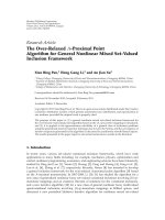
The BER versus E
b
/N
0
performances of the MMSE and
the minimum BER DS-CDMA systems are shown in Figure 3
for different number of users N.FromFigure 3, it is seen that
when N
= 1, the performances of the MMSE and minimum
BER systems are almost the same for all values of E
b
/N
0
.
When N is increased, the overall performance of the system
is worse, however, as seen from Figure 3, there is a significant
gain by using the minimum BER system compared to the
minimum BER system. When the number of users are
increased, the overall BER versus E
b
/N
0
performance of the
system is worse because of multiuser interference (MUI). It
is seen that the proposed system is less sensitive to MUI than
the MMSE system. From Figure 3, it is seen that for example
for BER
= 10
−10
and N = 5, about 16.5dB in E
b
/N
0
can
be gained by the proposed minimum BER system over the
MMSE system. The proposed minimum BER system and
5 10152025303540
E
b
/N
0
(dB)
10
−15
10
−10
10
−5
10
0
BER
N = 5
N
= 3
N
= 5
N
= 1
N = 3
MMSE DS-CDMA system
BER DS-CDMA system
Figure 3: BER versus E
b
/N
0
performances of the MMSE DS-
CDMA system (
···◦···) and the proposed minimum BER DS-
CDMA system (
−×−)fordifferent number of users N ∈{1,3,5},
when M
= 7, L = 5, and l = 0. When N increases, then the
performance curves move upwards.
the MMSE system have the same number of receiver filter
coefficients in all the filters when equal values of M, N, L,
δ,andl are used. The transmitter filters in both systems
are identical. The proposed system is more complicated
to design than the MMSE system, but after the filters are
found, the MMSE and minimum BER filters have the same
complexity. The proposed method is iterative, and when
finding the minimum BER filters, several sums of K elements
must be found, so the design complexity of the proposed
algorithm is significantly higher than the closed form MMSE
design complexity; see (9). However, the significant gain of
the proposed system might justify the increase in design
complexity, and, in addition, the proposed method can be
used to find linear filters with block memory which has the
minimum BER versus E
b
/N
0
performance.
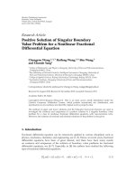
Figure 4 shows the BER versus E
b
/N
0
performance for
different number of users N of the proposed minimum BER
DS-CDMA system and the MMSE DS-CDMA system when
M
= 31, L = 5, and l = 0. Notice that the ranges of the
axis of Figures 3 and 4 are different. It is seen from Figure 4
that the difference between the MMSE and minimum BER
systems is very small when M
= 31. It is seen that the overall
performances of the systems are improved when M increases
since more bandwidth is used, that is, more redundancy
is introduced when M is increased. In this case, the small
improvement of performance between the MMSE and the
minimum BER receiver filters does not justify the increase
of design complexity introduced by the proposed minimum
BER receiver. These observations are in agreement with
earlier publications where minimum BER and MMSE filters
are compared where it is shown that when the filter length
is increased in the receiver filter, the difference between the
10 EURASIP Journal on Wireless Communications and Networking
−50 5 101520
E
b
/N
0
(dB)
10
−15
10
−10
10
−5
10
0
BER
N = 5
N
= 1
N
= 3
MMSE DS-CDMA system
BER DS-CDMA system
Figure 4: BER versus E
b
/N
0
performances of the MMSE DS-
CDMA system (
···◦···) and the proposed minimum BER DS-
CDMA system (
−×−)fordifferentnumberofusersN ∈{1,3, 5},
when M
= 7, L = 5, and l = 0. When N increases, then the
performance curves move upward.
MMSE and minimum BER filters is small; see for example
[11].
Figure 5 shows the BER versus E
b
/N
0
performances of
the MMSE and the proposed minimum BER systems when
M
= 7, L = 5, and N = 3andl ∈{0,1, 2}. When l increases,
the performance of the two systems improves. From Figure 5,
it is seen that a significant improvement can be achieved by
increasing l from 0 to 1 in this example, however, there is
only a small improvement in performance when l increases
from 1 to 2. This shows that there is a significant advantage to
introduce receiver filters with memory in DS-CDMA uplink
communication systems.
5.1. Effect of channel estimation errors
It was assumed that the receiver knows exactly all the channel
coefficients. This is not realistic in all practical situations.
Assume that the receiver is optimized for the channel transfer
functions C
i
(z), however, due to channel estimation errors,
the channel coefficients used in the communication system
are
C
i
(z), where the transfer functions C
i
(z)and
C
i
(z)have
the same order and size. Let
h
i
contain the L + 1 scalar
channel coefficients corresponding to
C
i
(z). As a measure of
the mismatch (MM) between the actual channels
h
i
and the
channels used in the optimization h
i
,MM= 1/N
N−1
i=0
h
i
−
h
i
2
is used. To generate the actual transfer function, the
relation
h
i
= h
i
+ q
i
was used, where q
i
hassize(L +1)× 1
and it is white complex Gaussian distributed with equal
variance for each component where the variance depends on
the current value of MM. It is assumed that the statistics of
the error vector (q
i
) stays constant for all the N channels
0 5 10 15 20 25
E
b
/N
0
(dB)
10
−15
10
−10
10
−5
10
0
BER
l = 0
l
= 1
l
= 2
l
= 2
l
= 1
MMSE DS-CDMA system
BER DS-CDMA system
Figure 5: BER versus E
b
/N
0
performances of the MMSE DS-
CDMA system (
···◦···) and the proposed minimum BER DS-
CDMA system (
−×−)fordifferentvaluesofreceiverfiltermemory
l
∈{0, 1, 2}, when M = 7, L = 5, and N = 3. When l increases, then
the performance curves move downward.
for a given value of the MM. When interpreting the size
of MM it is important to remember that
E[h
H
i
h
i
] = 1.
Figure 6 shows the BER versus MM performances of the
MMSE and minimum BER systems. Since the value of MM
depends on the realization of
h
i
, Monte Carlo simulations
were used. 10000 realizations of the actual channels
h
i
were
generated for each value of MM and then the BER, in (17),
was averaged for all these realizations. Figure 6 gives an
indication of the sensitivity of the MMSE and minimum BER
receiver to errors in the channel coefficients. It is seen that
the proposed minimum BER receiver is more robust against
channel estimation errors than the MMSE receiver.
5.2. Near-far resistance effect
Let u
i
(n) be the noise-free M × 1 vector time-series that
is the output of channel C
i
(z); see Figure 2.LetP
i
be the
received signal power from user number i. P
i
can be found
as P
i
= E[u
i
(n)
2
] = Tr {C
i
−
[I
2
⊗ w
i
w
H
i
]C
H
i
−
}. Let the
channel impulse responses be scaled such that all P
i
= P
for i
∈{1,2, , N − 1}. The received signal power P
0
from user number 0 can be different from the other received
powers. The near-far ratio (NFR) in dB is defined as NFR
=
10 log
10
P
0
/P.InFigure 7, the BER
0
versus NFR performance
is shown for the DS-CDMA systems using MMSE receiver
filters and the proposed minimum BER receiver filters. From
(17)and(20), it can be deduced that receiver filter number
i is chosen such that BER
i
is minimized. Since the near-
far resistance is measured as BER
0
versus NFR, the pro-
posed system has optimal near-far resistance among linear
receivers with block memory following the block model in
Figure 2.
A. Hjørungnes and M. Debbah 11
00.20.40.60.81
MM
10
−10
10
−8
10
−6
10
−4
10
−2
10
0
BER
MMSE DS-CDMA system
DS-CDMA system
Figure 6: BER versus MM performances of the MMSE DS-CDMA
system (
···◦···) and the proposed DS-CDMA system (−×−),
when l
= 0, M = 7, L = 5, N = 5, and E
b
/N
0
= 20 dB in all cases.
−20 −18 −16 −14 −12 −10 −8 −6 −4 −20
NFR (dB)
10
−20
10
−15
10
−10
10
−5
10
0
BER
0
MMSE DS-CDMA system
BER DS-CDMA system
Figure 7: BER
0
versus NFR performances of the MMSE DS-CDMA
system (
···◦···) and the proposed minimum BER DS-CDMA
system (
−×−), when l = 0, M = 7, L = 5, N = 5, and E
b
/N
0
=
20 dB in all cases.
6. CONCLUSIONS
Exact BER were derived for a DS-CDMA system using
receiver filters with block memory. Based on this expression,
a framework was developed for finding linear minimum BER
receiver filters with block memory. A numerical iterative
optimization algorithm was proposed that is able to converge
to a locally optimal solution. The proposed receiver filters
with block memory can be found through a numerical
optimization procedure. Numerical examples showed that
the proposed minimum BER receivers can perform sig-
nificantly better than the MMSE receivers with the same
filter memory. It was shown that by introducing memory
into the receiver filters, that is, by allowing l>0, a
significant performance gain of the DS-CDMA system was
(a)
(c)
(b)
P
Figure 8: Illustration of the situation in the proof of Lemma 1.
(a) represents the hypersphere in
R
1×2(l+1)M
with radius 1 and
center at the origin. The shaded sector of (b) represents the part
of the cone in
R
1×2(l+1)M
with vertex at the origin that is lying
inside the hypersphere with respect to the receiver inner product.
(c) represents the ith receiver that lies outside the cone in (b).
P represents the hyperplane that lies between the cone and the
ith receiver, passing through the origin, chosen such that the
reflection of the i receiver using the receiver inner product about
the hyperplane P lies inside the cone.
achieved. Several properties of the minimum BER filters
with block memory were also identified. The results might
be extended to regular constellations such as multilevel
PAM, QAM, and PSK. These constellations will require a
significantly larger number of vectors containing all possible
sent signal combinations, such that the final SER expressions
will contain a large number of terms.
APPENDICES
A. PROOF OF LEMMA 1
Proof. Observe first that if r
i
has a component in the
set
span
(t
(i)
k
(n))
H
[Φ
(l,M)
v
]
−1
⊥
, where the operator ⊥
means the orthogonal complement with respect to the
receiver inner product of the set it is applied to, this
component will not contribute anything to the expression
of the BER, see (17)and(20),butitwillreducethe
length of r
i
that can be used by ith receiver component
that lies in span
{(t
(i)
k
(n))
H
[Φ
(l,M)
v
]
−1
}. Therefore, the com-
ponent of the optimal MISO receiver r
i
−
filter that lies in
span
(t
(i)
k
(n))
H
[Φ
(l,M)
v
]
−1
⊥
is zero.
From the definition of linear FIR equalizable channels
and due to the result in (14), it follows that the vec-
tors
Re
(t
(i)
k
(n))
H
[Φ
(l,M)
v
]
−1
,Im
(t
(i)
k
(n))
H
[Φ
(l,M)
v
]
−1
∈
R
1×2(l+1)M
form a cone whose vertex is at the origin. Assume
that the optimal receiver [Re
{r
i
−
},Im{r
i
−
}] lies outside this
cone, but on the hypersphere in
R
1×2(l+1)M
with radius 1 and
center at the origin. Let P be a hyperplane in
R
1×2(l+1)M
that
lies between the cone and the ith receiver, passing through
the origin, chosen such that the reflection of the ith receiver
with respect to the hyperplane P using the receiver inner
product lies inside the cone. This situation is illustrated in
Figure 8. The reflection of the receiver with respect to P using
the receiver inner product then has a greater or equal receiver
inner product with all the vectors that generate the cone
compared to the original receiver outside the cone. Since
12 EURASIP Journal on Wireless Communications and Networking
the Q-function is monotonic decreasing, it is clear that the
BER using the reflection is smaller than when the ith receiver
lies outside the cone. Since the receiver lying outside the
cone and the index i were chosen arbitrarily, it is impossible
that the optimal receiver filters lie outside the receiver-signal
cones.
B. THE Q-FUNCTION AND ITS APPROXIMATIONS
The Q-function is a positive monotonic decreasing function
defined for real numbers x as follows:
Q(x)
=
1
√
2π
∞
x
e
−t
2
/2
dt. (B.1)
This means that the function Q(x) is equal to the proba-
bility that a real zero-mean unit-variance Gaussian random
variable is greater than the real number x. The following
approximations are used [19]:
Q(x)
≈
⎧
⎪
⎪
⎪
⎪
⎨
⎪
⎪
⎪
⎪
⎩
1
√
2πx
e
−x
2
/2
, forlargepositivevaluesofx,
1
2
−
1
√
2π
x, for values of x close to zero.
(B.2)
C. PROOF OF PROPOSITION 1
Proof. Assume that not all the noise-free eyes are open. This
means that there exists at least one noise-free eye that is
closed, for example, the one with index number i,wherei
∈
{
0, 1, , N −1}.From(20), it can be seen that BER
i
≥ 1/2K,
which implies that BER
≥ 1/2K.
ACKNOWLEDGMENTS
The authors thank to Marius S
ˆ
ırbu for fruitful discussions
related to this paper. Part of this work was presented in [22].
This work was supported by the Research Council of Norway
project 176773/S10 called OptiMO and the Aurora project
entitled “Communications under Uncertain Topologies.”
This work was supported by Alcatel-Lucent within the
Alcatel-Lucent Chair on flexible radio at SUPELEC.
REFERENCES
[1] S. Verd
´
u, “Minimum probability of error for asynchronous
Gaussian multiple-access channels,” IEEE Transactions on
Information Theory, vol. 32, no. 1, pp. 85–96, 1986.
[2] R. Lupas and S. Verd
´
u, “Near-far resistance of multiuser
detectors in asynchronous channels,” IEEE Transactions on
Communications, vol. 38, no. 4, pp. 497–507, 1990.
[3] A. J. Viterbi, “Very low rate convolution codes for maximum
theoretical performance of spread-spectrum multiple-access
channels,” IEEE Journal on Selected Areas in Communications,
vol. 8, no. 4, pp. 641–649, 1990.
[4]D.GuoandS.Verd
´
u, “Multiuser detection and statistical
mechanics,” in Communications, Information and Network
Securit y, V. Bhargava, H. V. Poor, V. Tarokh, and S. Yoon,
Eds., pp. 229–277, chapter 13, Kluwer Academic Publishers,
Dordrecht, The Netherlands, 2002.
[5] S. Shamai and S. Verd
´
u, “The impact of frequency-flat fading
on the spectral efficiency of CDMA,” IEEE Transactions on
Information Theory, vol. 47, no. 4, pp. 1302–1327, 2001.
[6] S. Verd
´
u and S. Shamai, “Spectral efficiency of CDMA with
random spreading,” IEEE Transactions on Information Theory,
vol. 45, no. 2, pp. 622–640, 1999.
[7]D.GuoandS.Verd
´
u, “Replica analysis of large-system
CDMA,” in Proceedings of the IEEE Information Theory
Workshop, pp. 22–25, Paris, France, March-April 2003.
[8] X. Wang, W S. Lu, and A. Antoniou, “Constrained minimum-
BER multiuser detection,” IEEE Transactions on Signal Process-
ing, vol. 48, no. 10, pp. 2903–2909, 2000.
[9] C C. Yeh, R. Lopes, and J. R. Barry, “Approximate minimum
bit-error rate multiuser detection,” in Proceedings of the IEEE
Global Telecommunications Conference (GLOBECOM ’98),
vol. 6, pp. 3590–3595, Sydney, Australia, November 1998.
[10] I. N. Psaromiligkos, S. N. Batalama, and D. A. Pados, “On
adaptive minimum probability of error linear filter receivers
for DS-CDMA channels,” IEEE Transactions on Communica-
tions, vol. 47, no. 7, pp. 1092–1102, 1999.
[11] C C. Yeh and J. R. Barry, “Adaptive minimum bit-error
rate equalization for binary signaling,” IEEE Transactions on
Communications, vol. 48, no. 7, pp. 1226–1235, 2000.
[12] S. Chen, A. K. Samingan, B. Mulgrew, and L. Hanzo, “Adaptive
minimum-BER linear multiuser detection for DS-CDMA
signals in multipath channels,” IEEE Transactions on Signal
Processing, vol. 49, no. 6, pp. 1240–1247, 2001.
[13] X. Wang and H. V. Poor, “Blind equalization and multiuser
detection in dispersive CDMA channels,” IEEE Transactions on
Communications, vol. 46, no. 1, pp. 91–103, 1998.
[14] G. B. Giannakis, Y. Hua, P. Stoica, and L. Tong, Eds., Signal
Processing Advances in Wireless and Mobile Communciations,
vol. I-II, Prentice-Hall, Upper Saddle River, NJ, USA, 2001.
[15] P. P. Vaidyanathan, Multirate Systems and Filter Banks,
Prentice-Hall, Englewood Cliffs, NJ, USA, 1993.
[16] A. Scaglione, G. B. Giannakis, and S. Barbarossa, “Redundant
filterbank precoders and equalizers part I: unification and
optimal designs,” IEEE Transactions on Signal Processing
,
vol. 47, no. 7, pp. 1988–2006, 1999.
[17] M. L. Honig, P. Crespo, and K. Steiglitz, “Suppression of near-
and far-end crosstalk by linear pre- and post-filtering,” IEEE
Journal on Selected Areas in Communications,vol.10,no.3,
pp. 614–629, 1992.
[18] S. Haykin, Adaptive Filter Theory, Prentice-Hall, Englewood
Cliffs, NJ, USA, 2nd edition, 1991.
[19] P. Galko and S. Pasupathy, “Optimization of linear receivers
for data communication signals,” IEEE Transactions on Infor-
mation Theory, vol. 34, no. 1, pp. 79–92, 1988.
[20] D. G. Luenberger, Linear and Nonlinear Programming,
Addison-Wesley, Reading, Mass, USA, 2nd edition, 1984.
[21] D. V. Sarwate and M. B. Pursley, “Crosscorrelation properties
of pseudorandom and related sequences,” Proceedings of the
IEEE, vol. 68, no. 5, pp. 593–619, 1980.
[22] A. Hjørungnes and M. Debbah, “Minimum BER FIR receiver
filters for DS-CDMA systems,” in Proceedings of the IEEE
Global Telecommunications Conference (GLOBECOM ’05),
vol. 4, pp. 2287–2291, St. Louis, Mo, USA, November 2005.