Báo cáo hóa học: "Research Article Broadcast Reserved Opportunity Assisted Diversity Relaying Scheme and Its Performance Evaluation" potx
Bạn đang xem bản rút gọn của tài liệu. Xem và tải ngay bản đầy đủ của tài liệu tại đây (729.46 KB, 9 trang )
Hindawi Publishing Corporation
EURASIP Journal on Wireless Communications and Networking
Volume 2008, Article ID 521834, 9 pages
doi:10.1155/2008/521834
Research Article
Broadcast Reserved Opportunity Assisted Diversity Relaying
Scheme and Its Performance Evaluation
Xia Chen,
1
Honglin Hu,
1
Shengyao Jin,
1
and Hsiao-Hwa Chen
2
1
Shanghai Research Center for Wireless Communications (SHRCWC), Shanghai 200050, China
2
Department of Engineering Science, National Cheng Kung University, 1 University Road, Tainan City 701, Taiwan
Correspondence should be addressed to Hsiao-Hwa Chen,
Received 29 December 2007; Accepted 2 March 2008
Recommended by Jong Hyuk Park
Relay-based transmission can over the benefits in terms of coverage extension as well as throughput improvement if compared
to conventional direct transmission. In a relay enhanced cellular (REC) network, where multiple mobile terminals act as relaying
nodes (RNs), multiuser diversity gain can be exploited. We propose an efficient relaying scheme, referred to as Broadcast Reserved
Opportunity Assisted Diversity (BROAD) for the REC networks. Unlike the conventional Induced Multiuser Diversity Relaying
(IMDR) scheme, our scheme acquires channel quality information (CQI) in which the destined node (DN) sends pilots on a
reserved radio resource. The BROAD scheme can significantly decrease the signaling overhead among the mobile RNs while
achieving the same multiuser diversity as the conventional IMDR scheme. In addition, an alternative version of the BROAD
scheme, named as A-BROAD scheme, is proposed also, in which the candidate RN(s) feed back partial or full CQI to the base
station (BS) for further scheduling purpose. The A-BROAD scheme achieves a higher throughput than the BROAD scheme at the
cost of extra signalling overhead. The theoretical analysis given in this paper demonstrates the feasibility of the schemes in terms
of their multiuser diversity gains in a REC network.
Copyright © 2008 Xia Chen et al. This is an open access article distributed under the Creative Commons Attribution License,
which permits unrestricted use, distribution, and reproduction in any medium, provided the original work is properly cited.
1. INTRODUCTION
Recently, multihop relaying transmission has attracted con-
siderable attention due to its potential to enhance coverage
and capacity as well as its flexibility if compared with single-
hop transmission. The primary advantage of the multihop
relaying comes from the reduction in the overall path loss
between a base station (BS) and a destined node (DN).
Another benefit of the multihop relaying is its path diversity
gain achieved by selecting the most favorable multihop
path in the shadowed environment. This diversity gain
will increase as the number of potential relaying nodes
(RNs) increases, and as the possibility of finding an RN
with a lower path loss increases as well. The approach of
augmenting cellular communication coverage with multihop
relaying, which is referred to as relay enhanced cellular
(REC) network, has been considered in many B3G/4G
standardization-related researches [1–3].
In an REC network, where multiple mobile terminals
act as RNs, the multiuser diversity gain can be exploited.
The multiuser diversity was first introduced by Knopp and
Humblet [4], then extended by the works done by Tse
[5, 6], as a means to provide diversity against channel
fading in multiuser packet-switched wireless networks. The
multiuser diversity works based on the fact that, in a wireless
cellular network with multiple users whose channels vary
independently, it is likely that there is a user with a “very
good” channel at a given time. Assume that we allow some
degree of flexibility to delay transmissions until a user’s
channel condition is improved. The gain can be achieved
by allocating the majority of system resources to a good
user at that given time. This approach has been adopted for
the downlink design of CDMA2000 and WCDMA systems,
that is, 1xEV-DO [7] and high-speed downlink packet access
(HSDPA) [8]. Nevertheless, the aspects related to the fairness
among the users also have to be considered. To address
the fairness issue, some proper scheduling methods should
be adopted, for example, proportional fair (PF) scheduling
[9].
The multiuser diversity gain can only be exploited
once in a single-hop network. However, in a multihop
cellular network, there is an opportunity to exploit multiuser
diversity in each hop. To achieve the multiuser diversity
in a multihop network, a relaying method was proposed
2 EURASIP Journal on Wireless Communications and Networking
in [10], where the multiuser diversity is exploited in each
hop by selecting the next RN based on the instantaneous
channel quality. However, selecting only one RN reduces
the opportunity of capturing a good channel in the next
hop. Hence, [11] suggested that a BS should coordinate
the cooperative relaying method, namely, induced multiuser
diversity relaying (IMDR). The scheme works based on
the assumption that there likely exist a certain number
of mobile RNs in a cellular network. The IMDR uses the
broadcast feature of the wireless channel to induce the
multiuser diversity through a two-phase process. However,
in this scheme, in order to get the knowledge of channel
quality information (CQI), it needs complicated interaction
protocolamongpotentialRNsaswellastheDN.Moreover,it
might result in unnecessary data broadcasting, thus wasting
power and causing interference.
In this paper, we propose a more efficient relaying
scheme, called broadcast reserved opportunity assisted diver-
sity (BROAD) scheme. In this scheme, the BS first broadcasts
to all possible RNs and DN such that a resource opportunity
is reserved for the DN. Next, the DN which needs relaying
broadcasts its pilots on the reserved resource opportunity,
and all the volunteer RNs probe the channels between the
DN and themselves on the reserved opportunity. Then, the
BS broadcasts data packets. The volunteer RNs with good
channels from the BS and to the DN receive the data, and
the RNs without good links remain silent to save energy.
Finally, these RNs with good channels forward the data
to the DN. The multiuser diversity could be retained with
much less cost than that needed in the IMDR scheme.
In addition, based on the proposed BROAD scheme, an
alternative version named as A-BROAD scheme is also
suggested, in which the candidate RNs can feed back
the full or partial CQI to the BS for further scheduling
purpose. Therefore, the BS can make efficient scheduling to
achieve much better throughput performance. In addition,
the BS can avoid useless feedback/broadcasting because
the BS only broadcasts data packets to the most capable
RN(s).
The rest of the paper is organized as follows. Section 2
gives a brief description of the system model. In Section 3,
for comparison purpose, the conventional IMDR scheme is
introduced and our BROAD scheme is proposed. The system
performance is analyzed and the feasibility of achieving
multiuser diversity is discussed in Section 4.InSection 5,we
give the simulation results and make overhead comparison
of the IMDR scheme and our BROAD scheme. Finally, we
conclude the paper in Section 6.
2. SYSTEM MODEL
We consider an REC network with a circular cell whose
radius is D. The BS is located at the center of the cell, with
a maximum transmit power level of P
T
. The BS transmits
a signaling channel that can be received by all user nodes
in the coverage area. In our modeling, there are a total of
U mobile users, distributed uniformly in the coverage area.
Here we suppose that all the mobile users could act as RNs.
The probability density function (pdf) of the user’s distance
d from the BS is given by
Pr(d)
=
2d
D
2
,0≤ d ≤ D. (1)
Each packet has a large delay tolerance and includes the
identity (e.g., physical address) of the DN. All the nodes in
the network are assumed to be equipped with single-element
antenna, and the transmissions between all the nodes are
constrained to a TDD mode; that is, any node cannot
transmit and receive simultaneously. Let r and t denote the
received and the transmitted signals, respectively, and let n
denote the additive white Gaussian noise (AWGN) with zero
mean and variance of N
0
. We have the received signal as
r
=
P
T
ht + n,(2)
where h can be the channel between either the BS (acting
as source) and the DN, the BS and the potential RN, or
the potential RN and the DN. h is modeled by taking
into account three effects [12]: the shadowing effects s,
the attenuation due to the distance d, and the small-scale
random fading effect z as
h
=
K
1
d
λ
z
√
s,(3)
where λ is the path loss exponent, ranging from two (free
space) to four, and K is a constant depending on the antenna
design. The shadowing component is assumed to have a log-
normal distribution whose pdf can be described as [12]
f
s
(x) =
1
xδ
s
√
2π
e
−(ln x−μ
s
)
2
/2δ
2
s
,(4)
with μ
s
and σ
s
being the mean and standard deviation of ln x.
Without loss of generality, we assume μ
s
= 0, meaning that
the median of s is one. For the small-scale fading, we assume
a non-line-of-sight (NLOS) scenario and z is a zero-mean
unit-variance complex Gaussian random variable.
3. INDUCED MULTIUSER DIVERSITY PROTOCOLS
Inthissection,wefirstgiveabriefreviewofhowthe
conventional IMDR scheme works, and then introduce
our proposed BROAD scheme. These two schemes can
both induce the multiuser diversity in a multihop cellular
network, but operate in quite different patterns.
3.1. Conventional IMDR scheme
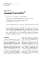
The conventional IMDR scheme is shown in Figure 1.Itis
based on the assumption that there exists a large amount
of mobile RNs in a cellular network. The IMDR uses the
broadcast feature of wireless channel to induce multiuser
diversity. First, the data packets are broadcasted by the BS
with its maximum bit rate. Some users in the cell coverage
area are likely to receive the data packets. These users, acting
as RNs, wait till the occurrence of a “good channel” to
Xia Chen et al. 3
BS
RN
RN
RN
RN
DN i
Induced multi-user diversity
Figure 1: Conventional IMDR scheme.
T1
Feeding
T2
CQI probing
T3
Delivery
T4
Figure 2: Detailed time-span of the IMDR scheme.
transmit the data packets to the DN with high bit rate.
Transmitting to multiple RNs induces multiuser diversity
into the system; thus this scheme is named as IMDR [2].
Note that it is unavoidable for each potential RN to get
the CQI between the DN and itself, so as to judge whether
it can deliver the data to the DN with a particular bit
rate or not. Therefore, the phase to probe the CQI cannot
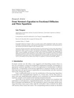
be ignored. In order to explain the conventional IMDR
scheme more clearly, we illustrate its detailed time-span in
Figure 2, where the whole process is divided into three main
phases, that is, the feeding phase, the CQI probing phase,
and the delivery phase [3]. In Figure 2, all the T spans
indicate the signaling duration. The signaling procedure of
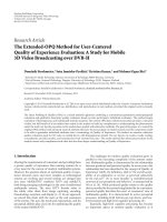
the conventional IMDR protocol is shown in Figure 3.Next,
we describe the protocol in detail.
Step 1. As shown in Figure 3, during the T1, the BS broad-
casts the DN information, including the DN ID, QoS require-
ment, and so forth.
Step 2. In the feeding phase, the BS broadcasts the data for
the DN to all the potential RNs with the maximum bit rate
R
max
at maximum transmit power. Any user nodes which
receive the data packets in the feeding phase act as the RNs in
the delivery phase.
Step 3. During the T2, if the DN successfully receives the
data, it will send back an R-ACK to the BS. Then, the BS will
broadcast a D-REL to all the RNs, and all the RNs release this
relay process.
Step 4. If there is no R-ACK signaling from the DN, in
the CQI probing phase, the BS is kept inactive. Each RN
continuously tracks the quality of the wireless link to the
neighboring users as well as their identity. In this stage, all the
RNsaswellastheDNwillbroadcastpilotssoastoacquire
CQI, and hand-shaking protocols are needed between them.
Note that more complex protocols are required if some
potential cooperative transmission techniques are adopted.
BS RNs DN
Feeding phase
DN ID, QoS, etc.
Data packets
R-ACK from DN
D-REL
R-ACK from RNs
Pilot activation
CQI probing phase
Complicated handshaking
procedure to acquire CQI
among potential RNs
and DN
.
.
.
RNs forward data packets
R-ACK from DN
D-REL
Delivery phase
:
Denoting the signal procedure if the DN can receive data
packets in the feeding phase
Figure 3: Conventional IMDR protocol illustration.
In addition, the RNs need to find out the DN and measure
the channel to the DN.
Step 5. During the T3, the hand-shaking is successfully built
among the RNs to the DN.
Step 6. In the delivery phase, the BS is kept inactive and
only the transmissions from the RNs to the DN are allowed.
If an RN is able to achieve a transmission bit rate, greater
than or equal to a threshold R
0
which is a system parameter
and will be discussed later in Section 4, over the channel to
the DN, then the RN transmits the data packets to the DN.
The medium access control can be either a contention-based
method or a BS coordinated non-contention-based method.
Step 7. During the T4, upon successful reception, the DN
sends an R-ACK signal to the BS. Consequently, the BS
broadcasts a data release (D-REL) signal, and other RNs
release that data packet. If the BS does not receive R-ACK
corresponding to a data packet in a predefined time interval,
that data packet is considered lost and a D-REL signal is
broadcasted by the BS. That data packet may be considered
for retransmission later.
3.2. Proposed BROAD scheme
In the conventional IMDR scheme, in order to acquire
the CQI, complicated handshaking signaling interaction
would certainly incur among the potential RNs and the
DN during the CQI probing phase. As can be seen from
4 EURASIP Journal on Wireless Communications and Networking
Figure 3, after receiving the pilot activation signal from the
BS, all the potential RNs will send their pilots through
certain contention-based or centralized mechanism. The
CQI probing procedure continued until each RN successfully
built its connection to the DN and obtained the CQI to the
DN.
However, in the proposed BROAD scheme, the DN is
informed by the BS to transmit its pilots on a reserved
resource opportunity in advance. Thus, the BROAD scheme
can avoid the complex signaling interaction during the CQI
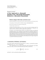
probing phase. The time-span of the proposed BROAD
scheme is illustrated in Figure 4.WecanseefromFigure 4
that the CQI probing in the BROAD scheme is proceeded
in advance compared to that in the IMDR scheme. Figure 5
illustrates the detailed protocol. Next, we will describe the
protocol step by step.
Step 1. as shown in Figure 5, during the T1, the BS broad-
casts the DN information, including the DN ID, QoS require-
ment, and so on. In addition, the BS broadcasts that the DN
will broadcast its pilots on some reserved opportunities, that
is, resource blocks. Here, it is assumed that the downlink-
broadcasted control signaling could normally reach the DN,
but not vice versa.
Step 2. in the CQI probing phase, the DN broadcasts its
pilots on the reserved opportunity and the RNs probe their
channels to the DN. Note that in this stage, the BS does
not need to be absolutely inactive as in the conventional
IMDR, but only needs to be inactive on the reserved
resource opportunity assigned to the DN. Moreover, this
stage does not need the complex hand-shaking protocols
between the RNs and the DN, as those in the IMDR
scheme.
Step 3. during the T2, if the BS receives the pilots from the
DN during the CQI probing phase and finds that the data
could be directly sent to the DN now, rather than by relaying,
then the BS will broadcast a D-REL to all the RNs, and all the
RNs release this relay process.
Step 4. if the BS notices that the DN still needs the relaying,
in the feeding phase, the BS broadcasts the data for the DN
to all the RNs with the maximum bit rate and maximum
transmit power. Note here that since the RNs all know the
channel information to the DN, those RNs which could
not offer the relaying could be inactive for this specific
relaying process. These capable RNs receive the data from
the BS. Here, we should note an alternative procedure for
our proposed BROAD scheme, namely, alternative BROAD
(A-BROAD). That is, during the T2(Step 3), if an RN finds
that it is suitable to act as an RN for the DN (by evaluating
the channel between the BS and the DN), it could report
the channel information to the BS for more sophisticated
scheduling. Those RNs which find their channel worse than
a threshold keep silent. Then, in the following feeding
phase (Step 5), the BS could send the data to the selected
RNs by the dedicated channels, rather than through the
broadcasting channel. Note that the broadcasting channel
T1
CQI probing
T2
Feeding
T3
Delivery
T4
Figure 4: Detailed time-span of the BROAD scheme.
BS RNs DN
CQI probing phase
DN ID, QoS,
reserved opportunity, etc.
Broadcast pilots on reserved opportunity
Need no relay, D-REL
Broadcast data packets
R-ACK from DN
D-REL
Feeding phase
RNs forward data packets
R-ACK from DN
D-REL
Delivery phase
:
Denoting the signaling procedure when BS receives
pilots during the CQI probing phase
:
Denoting the signaling procedure when BS receives
data packets during the feeding phase
Figure 5: Illustration of the proposed BROAD protocol.
normally could not support a huge amount of dedicated
data for a specific user. Moreover, the BS thus could easily
manage advanced cooperative relaying schemes among the
selected RNs. The A-BROAD scheme is especially useful for
the scenario where there does not exist a large amount of
RNs near the DN, or, namely, fixed relay station scenario.
Note in this case that the IMDR scheme is not efficient and
even could not work, because it might happen that none of
the RNs could act as the RN for the DN. Comparably, in
the enhanced A-BROAD scheme, since the BS could receive
the feedback from those candidate RNs, the BS could easily
decide whether it needs to broadcast the data to the DN or
not; in other words, useless feeding/broadcasting could be
avoided.
Step 5. during the T3, if the DN successfully received the
data, it will send back an R-ACK to the BS. Then, the BS will
broadcast a D-REL to all the RNs, and all the RNs release
this relay process. (Here if the RNs could hear the R-ACK
from the DN, they could release the relaying process directly.
Hence the relay process can be terminated, and Steps 6 and
7 can be saved.) Otherwise, hand-shakings between the RNs
and the DN should be built.
Step 6. this step is the same as Step 6 in the IMDR scheme.
Xia Chen et al. 5
Step 7. this step is the same as Step 7 in the IMDR scheme.
However, if the RNs could hear the R-ACK from the DN, all
the RNs could release the relaying process directly.
From the above description of conventional IMDR and
our proposed BROAD schemes, we can see clearly that our
scheme has the following advantages.
(1) Our scheme can greatly simplify the procedure of
CQI probing compared with conventional IMDR
scheme, thus saving a lot of overhead as well as
reducing the delay.
(2) In the feeding phase, since all the RNs have already
known whether they could offer help as an RN or not,
only those which could act as an RN will buffer or
decode the received data. The other RNs could ignore
the broadcasting, thus reducing the overhead.
(3) In the CQI probing phase, the BS does not need to
be inactive on all the radio resources. For example,
when OFDMA is applied, the BS only needs to avoid
using the dedicated subcarriers assigned to the DN
for CQI probing. Note that in the IMDR scheme,
since all the users need to broadcast on at least part
of the subcarriers if they use FDM mode, they have to
occupy the full band. Otherwise, TDM mode should
be used and delay will be involved.
(4) The BS has two chances to send the D-REL to the
RNs during the whole process, that is, in Steps 3 and
5. Comparably, it is not possible to send the D-REL
during Step 5 in the IMDR scheme.
4. SYSTEM PERFORMANCE ANALYSIS
As for (1), the expression of the SNR is straightforward. The
SNR at the receiver can be expressed as
γ
=
|
h|
2
P
T
δ
2
n
=|h|
2
ηD
λ
K
,(5)
where, for a particular user location, the parameters s and d
in (3)arefixed,andη is the median of SNR when the mobile
is at the maximum d (i.e., D, the apex of the hexagonal cell),
defined as
η
=
KP
T
σ
2
n
D
λ
. (6)
Thus, h is equal to a scalar multiplied by z which takes
a unit-variance Rayleigh distribution. Therefore, h is a
complex Gaussian random variable. Its squared magnitude
is exponentially distributed and the pdf of γ is
f (γ)
=
1
γe
−γ/γ
, γ ≥ 0, (7)
where
γ is easily derived as
γ =
ηD
λ
K
E
|
h|
2
=
ηD
λ
K
Kd
−λ
sE
|z|
2
= η
D
d
λ
s.
(8)
Hence, the short-term averaged throughput can be obtained
from
Y = log
2
1+γ
=
1
ln 2
ln
1+γ
. (9)
Then, we derive the cumulative distributive function (cdf) of
Y over log-normal shadow fading s, conditioned on d.Itis
obvious that the
Y is a monotonic function of γ. Assuming
that the variables y and γ
0
are related by y = (1/ ln)2 ln(1 +
γ
0
), as in (9), we have
Pr
Y ≤ y | d
=
Pr
γ ≤ γ
0
| d
. (10)
As we noted that
γ is a monotonic function of s,ands
is a log-normal random variable, after some mathematical
manipulation as in [13], the cdf of
Y conditioned on d can
be well approximated by a Gaussian cdf of the form
Pr
Y ≤ y | d
=
1 −
1
2
er f c
⎛
⎝
y − m
y
2δ
y
⎞
⎠
, (11)
where m
y
and δ
y
can be expressed as
m
y
(d) =−
1
ln(2)
ln
d
λ
ηD
λ
,
δ
y
=
δ
s
ln(10)
10 ln(2)
.
(12)
It is observed that given system and propagation parameters,
the mean of the distribution is a simple function of d.We
also see that the standard deviation is related linearly to δ
s
.
As an example, in order to illustrate the influence of
user location on the spectral efficiency, we plot the cdf of
short-term averaged throughput when d/D
= 0.05, 0.10,
0.95, respectively, as shown in Figure 6. From the figure, it
is noted that for users at different locations, their spectral
efficiency can differ quite a lot. Given an outage probability
requirement, the users which are located near the BS can
receive with several times higher bit rate than those located
far from the BS. Hence, for such a scenario with enough
high user density, it is reasonable to assume that in each time
instant there exists at least one user which can receive the
transmitted data packets with a bit rate of R
max
in the feeding
phase, as claimed in the conventional IMDR scheme or our
proposed BROAD scheme.
As proved in [11], because of the induced multiuser
diversity, the IMDR or our proposed BROAD as well as
A-BROAD scheme can improve the system throughput
compared to the single-hop transmission if
1
R
0
<ξ
1
R
av
−
1
R
max
, (13)
where R
av
is the average BS transmission rate for single-hop
transmission with the proportional fairness (PF) scheduling,
and ξ is defined as the medium access control gain, which
shows the average portion of the radio resource (e.g., trans-
mission time) that can be allocated to the competitors for
6 EURASIP Journal on Wireless Communications and Networking
0 5 10 15 20 25 30
Average throughput ( y)
0
0.1
0.2
0.3
0.4
0.5
0.6
0.7
0.8
0.9
1
Pr (Y ≤ y|d)
d/D = 0.95
d/D
= 0.1 d/D = 0.05
Figure 6: Comparison of the cdf of short-term averaged through-
put across users, at preselected distances such that d/D
= (0.05, 0.10,
0.95).
a shared medium. For the non-contention-based medium
access control mechanisms, ξ
= 1. The detailed proof can
be found in [11].
It is noted from Figure 6 that the outage probability
mainly depends on the location of the users from the BS. The
nearer the user is located from the BS, the smaller the outage
probability will be at a certain bit rate. Like the conventional
IMDR scheme, the proposed BROAD scheme also assumes
that there exits at least one potential RN which can receive
with a bit rate of R
max
. The selection of R
max
is quite subtle.
On one hand, if R
max
is very large, then only a few users in
the coverage area can receive the data packets in the feeding
phase; on the other hand, decreasing R
max
will increase the
number of potential RNs but will also reduce the overall
throughput. The transmission rate R
max
may also be adjusted
based on the number of potential RNs; if the data packets
are not received by a reasonable number of mobile users, the
R
max
should be decreased.
Next, we will analyze the probability of existing M
potential RNs which can receive with R
max
error-free (e.g.,
quite low outage probability). Since the outage probability
has a strong connection with the location of users, we assume
that the potential RNs which can receive with R
max
during the
feeding phase are located within a certain radius (e.g., d/D
=
0.10) from the BS. Meanwhile, during the delivery phase
where the data packets should eventually be delivered to the
DN, the RNs should be located in the intersection area of the
two circles which center at the BS and the DN, respectively.
In other words, the shaded area in Figure 7 is regarded as the
effective area for the potential RNs. Finding the probability
of existing M potential RNs which can receive with R
max
is equivalent to computing the probability of existing M
users within the intersection area. The area, denoted by
ρ(d
SD
, d
R
max
), can be divided into two parts: ρ
1
, the lighter
shaded area which is the sector
ASB from the circle S,and
ρ
2
, the darker shaded area which is the addition of the two
ρ
1
ρ
2
S(BS)
D(DN)
RN
RN
RN
r
SD
r
R
max
A
B
Figure 7: Illustration of areas where RN is capable of receiving with
R
max
.
small areas in circle D enclosed by the arcs
AS and
SB. The
area of the sector
ASB is given by
ρ
1
= φd
2
R
max
, (14)
where φ is the angle ∠DSB. From the isosceles triangle ΔDSB,
it is straightforward to see that this angle is given by φ
=
arccos(d
R
max
/2d
SD
). The second part ρ
2
from the circle D
can be calculated as the total sector area
DSA minus the
triangular area ΔDSA. Hence, the area ρ
2
can be given as
ρ
2
= 2
⎡
⎣
π
2
−φ
d
2
SD
−
d
R
max
2
d
2
SD
−
d
2
R
max
4
⎤
⎦
. (15)
Adding the two parts together, we get the total area expressed
as
ρ
d
SD
, d
R max
=
ρ
1
+ ρ
2
= d
2
R
max
arccos
d
R
max
2d
SD
+ πd
2
SD
−2d
2
SD
arccos
d
R
max
2d
SD
−
d
R
max
d
2
SD
−
d
2
R
max
4
.
(16)
Since we have U users uniformly distributed in a circular area
of radius of D, the probability of finding M (M ≤ U)users
in the area ρ(d
SD
, d
R
max
)isgivenby
Pr
d
m
≤ d
R
max
=
ρ
d
SD
, d
R
max
πD
2
M
. (17)
It is observed from (17) that for a given M, the
probability is related to d
R
max
and d
SD
, that is, the distance
from the BS to the DN. In order to guarantee a high
probability of existing M users receiving with R
max
, the
parameter R
max
should be selected discreetly. As for the
number of RNs among the M potential relays, which have
the ability to forward the data packet to DN, it is related
to several aspects, for example, the parameter R
0
, the user
mobility, as well as τ
max
, which is defined as a maximal
tolerant delay of the data packets. Hence, it is quite difficult
to obtain a probability distribution function of how many
Xia Chen et al. 7
Table 1: Simulation parameters.
Cell radius 1000 m
Carrier frequency 2 GHz
FFT size 512
Bandwidth 5 MHz
Standard deviation of log-normal fading 8 dB
Propagation loss exponent 4
Time slot length 0.5 ms
Channel model TU
Mobility [30 90 150 210] km/h
RNs among the M potential RNs will have the ability to
forward the data packets with a bit rate greater than R
0
.It
is assumed that within the interval τ
max
→∞, the data packets
transmitted to the RNs will be delivered to the DN eventually.
That is, if τ
max
→∞, a packet can be kept waiting in a potential
RN until the occurrence of a very high rate channel to
the DN. For a moderate value of τ
max
, the mobility is very
important. The higher the user’s mobility is, the higher the
probability of a high bit rate channel in the second hop will
be. For a given mobility profile, a larger value of τ
max
results
in a more efficient exploitation of the mobility.
5. SIMULATION RESULTS AND OVERHEAD
COMPARISON
In this section, the simulation results are presented. In
addition, the overheads of our proposed BROAD scheme and
the conventional IMDR scheme are compared in detail.
5.1. Simulation results
We simulate a single-cell OFDMA-based system with a total
of U active users uniformly distributed in the coverage area.
In this simulation, the scheduling is initiated once there is
a new data packet waiting to be transmitted. The detailed
simulation parameters are presented in Ta ble 1 and the
scenario is based on the report of the WINNER project [14].
To show the effect of the multiuser diversity, we consider two
other systems as benchmarks: one is round-robin scheduling
scheme, that is, the BS transmits packets to the users in a
round-robin fashion; the other is the so-called opportunistic
scheduling scheme. To guarantee the fairness among the
users, the opportunistic scheduling is combined with the
proportional fairness (PF) criterion [9], and is referred to as
the O-PF scheme in this paper.
As described in Section 3, the proposed BROAD scheme
can induce the same multiuser diversity as the conventional
IMDR scheme but at lower overheads. Hence, there is no
difference between the two schemes in terms of the system
throughput, which is defined as the data rate used to transmit
data packets in this paper. Therefore, we only need to
evaluate the performance of the proposed BROAD scheme.
In this simulation, the R
av
is the average transmission bit
rate of the O-PF scheme by the BS. In addition, it should
be mentioned that τ
max
= 10 milliseconds, and each user
assumed a mobility of 30 km/h. If within the interval τ
max
Table 2: Number of dropped packets versus mobility for τ
max
=
50 milliseconds.
Mobility of users
30 km/h 90 km/h 150 km/h 210 km/h
Number of dropped packets 352 298 217 143
Table 3: Number of dropped packets versus τ
max
for velocity =
90 km/h.
τ
max
25 ms 50 ms 75 ms 100 ms
Number of dropped packets 418 367 312 257
there is no occurrence of such channel through which the
potential RN is able to transmit the data packets with a bit
rate greater than or equal to the system parameter R
0
, then
the data packets are considered lost.
Figure 8 illustrates the system throughput achieved by
the O-PF, the BROAD, and the A-BROAD schemes versus the
number of users in the coverage area. It should be mentioned
that these throughput curves are actually normalized by the
average achieved throughput of the round-robin scheme.
From Figure 8, we can obviously observe that the BROAD
scheme can achieve much better performance than the O-
PF scheme. The gain indicates that our BROAD scheme can
exploit the multiuser diversity efficiently. As expected, this
throughput gain increases as the number of users increases.
It is also observed that the A-BROAD scheme achieves the
highest throughput, because for the proposed A-BROAD
scheme, the BS can make sophisticated scheduling based on
the CQI between the BS and potential RNs as well as the CQI
between the potential RNs and the DN, which are fed back
to the BS by the potential RNs.
We also simulate the number of dropped packets versus
the mobility of users given a certain τ
max
, which is shown
in Ta bl e 2. In the simulation, the total number of users in
acellisU
= 80, and the simulation runs for 5000 times.
From Ta bl e 2, it is shown that as the mobility increases,
the number of dropped packets decreases accordingly. In
addition, given a certain mobility of users, we simulate the
number of dropped packets versus τ
max
, which is shown in
Ta ble 3 . Apparently, the larger the value τ
max
is, the less the
number of dropped packets will be. Obviously, both Tables 2
and 3 validate our above theoretical analysis.
5.2. Overhead comparison
Now we compare the overhead of our BROAD scheme with
that of the conventional IMDR scheme. For the sake of
simplicity, we make some general assumptions as follows:
(i) for OFDMA-based system with N subcarriers,
divided into n sub bands, each subcarrier could
transmit two bits;
(ii) M RNs in the area could receive the data packets from
the BS, but only M RNs are capable of forwarding the
data packets to the DN;
8 EURASIP Journal on Wireless Communications and Networking
Table 4: Overhead comparisons between BROAD and IMDR.
Comparison items IMDR BROAD
1. In the CQI probing phase, if complex
handshaking protocols are needed or
not?
Needed (if M RNs probe, it will cost
2M
×N/n bits)
∗
Not needed, but at the cost of broad-
casting log
2
(n) extra bits to indicate the
reserved sub-band
2. In the feeding phase, how many RNs
receive the data packets from the BS?
All the M RNs
Only those capable m RNs (other M
−
m RNs could be ignored, thus saving
power)
3. Resource using efficiency in the CQI
probing phase
Inefficient (BS needs to be inactive on
all the n sub-bands reserved for the
RNs)
More efficient (only 1 sub-band is
reserved for probing; other n-1 sub-
bands could be used)
4. In which step the relay process can be
terminated?
Only in Step 3 Both Steps 3 and 5
∗
More time slots (bits) are needed if we take handshaking protocols into account. Furthermore, power consumptions at the M RNsaswellastheinterference
to corresponding neighbor cells should be considered.
50 55 60 65 70 75 80 85 90 95 100
Number of users
1
1.5
2
2.5
3
3.5
4
4.5
Normalized average throughput
O-PF
BROAD
A-BROAD
Figure 8: Normalized average achieved throughput versus the
number of users.
(iii) each RN probes in one sub band in the IMDR
scheme;
(iv) the BS reserves one sub band for the DN to broadcast
in the BROAD scheme.
Then, in Ta ble 4 , we give a list of comparisons between
our BROAD scheme and the conventional IMDR scheme.
Following Ta bl e 4, we could see that if N
= 300, n =
25, M = 25, and m = 5, then the BROAD scheme could
save at least 2
×25 × 300/25 −5 = 595 bits.
The main difference between the A-BROAD scheme
and the BROAD scheme is that capable RNs will feed
back the CQI to the BS during T2(Step 3). Then the BS
can perform sophisticated scheduling; meanwhile useless
feeding/broadcasting can be avoided since the BS has the
CQI between the RNs and itself or even the CQI between
the RNs and the DN. In addition, in the A-BROAD scheme,
only a small number of RNs (e.g., two), rather than all
the M RNs, will forward the data packets to the DN. Thus
the overhead is further reduced. The enhanced A-BROAD
scheme is especially useful for the scenario where there does
not exist a large amount of RNs near the DN. If we assume
3-bit CQI for each sub band, the additional overhead for the
A-BROADschemeisthem capable RNs which feed back CQI
of 3
× n = 75 bits to the BS. Thus, the total overhead for the
A-BROADschemeis75+5
= 80 bits, which is still far less
than that of the IMDR scheme (at least 600 bits).
6. CONCLUSIONS
If compared to the conventional IMDR scheme, a more
efficient relaying scheme, that is, broadcast reserved oppor-
tunity assisted diversity (BROAD) scheme, is proposed in
this paper. In this proposed scheme, the DN sends pilots
on certain reserved resource which is broadcasted by the
BS in advance. The BROAD scheme can achieve the same
multiuser diversity as the IMDR scheme but with a consid-
erable less overhead. Furthermore, an enhanced A-BROAD
scheme is proposed to achieve even better performance if
potential RNs feed back CQI to the BS such that sophisticated
scheduling can be made. We give a theoretical analysis
for the feasibility of exploiting the multiuser diversity in a
multihop relay enhanced cellular network. Simulation results
and overhead comparisons show that our proposed schemes
outperform the conventional IMDR scheme significantly.
ACKNOWLEDGMENTS
The authors would like to gratefully acknowledge the
research grants from the Natural Science Foundation of
Shanghai (no. 07ZR14104) and the National Science Council
of Taiwan (NSC96-2221-E-006-345 and NSC96-2221-E-
006-346).
REFERENCES
[1] R. Pabst, B. H. Walke, D. C. Schultz, et al., “Relay-based
deployment concepts for wireless and mobile broadband
radio,” IEEE Communications Magazine, vol. 42, no. 9, pp. 80–
89, 2004.
Xia Chen et al. 9
[2] “IST-2003-507581 WINNER D3.4 version 1.0,” June 2005,
/>[3] CJK B3G Working Group White Paper, “Investigation on
Requirements and Enabling Technologies for the IMT-
Advanced Air Interface,” v0. 2 CCSA Draft, November 2006.
[4] R. Knopp and P. A. Humblet, “Information capacity and
power control in single-cell multiuser communications,” in
Proceedings of IEEE International Conference on Communica-
tions (ICC ’95), vol. 1, pp. 331–335, Seattle, Wash, USA, June
1995.
[5] D. N. C. Tse, “Multiuser diversity in the wireless networks,”
2000, Wireless Communication Seminar, Stanford University,
Stanford, Calif, USA.
[6] P. Viswanath, D. N. C. Tse, and R. Laroia, “Opportunistic
beamforming using dumb antennas,” IEEE Transactions on
Information Theory, vol. 48, no. 6, pp. 1277–1294, 2002.
[7] Qualcomm, “1xEV: 1x evolution IS856 TIA/EIA standard
airlink overview,” November 2001.
[8] H. Holma, WCDMA for UMTS: Radio Access for Third
Generation Mobile Communications, John Wiley & Sons, New
York, NY, USA, 3rd edition, 2004.
[9] P. Larsson and N. Johansson, “Multiuser diversity forwarding
in multihop packet radio networks,” in Proceedings of IEEE
Wireless Communications and Networking Conference (WCNC
’05), vol. 4, pp. 2188–2194, New Orleans, La, USA, March
2005.
[10] T. Park, O S. Shin, and K. B. Lee, “Proportional fair schedul-
ing for wireless communication with multiple transmit and
receive antennas,” in Proceedings of the 58th IEEE Vehicular
Technology Conference (VTC ’03), pp. 1573–1577, Orlando,
Fla, USA, October 2003.
[11] K. Navaie and H. Yanikomeroglu, “Induced cooperative
multiuser diversity relaying for multihop cellular networks,” in
Proceedings of the 63rd IEEE Vehicular Technology Conference
(VTC ’06), vol. 2, pp. 658–662, Melbourne, Australia, May
2006.
[12] T. S. Rappaport, Wireless Communication: Princ iples and
Practice, Prentice Hall, Upper Saddle River, NJ, USA, 2nd
edition, 2001.
[13] S. Catreux, P. F. Driessen, and L. J. Greenstein, “Data
throughputs using multiple-input multiple-output (MIMO)
techniques in a noise-limited cellular environment,” IEEE
Transactions on Wireless Communications,vol.1,no.2,pp.
226–235, 2002.
[14] M. Failli, COST 207: Digital Land Mobile Radio Communica-
tions, European Communities, Luxemburg, Germany, 1989.