Báo cáo hóa học: " Research Article Time and Frequency Synchronisation in 4G OFDM Systems" pdf
Bạn đang xem bản rút gọn của tài liệu. Xem và tải ngay bản đầy đủ của tài liệu tại đây (955.63 KB, 9 trang )
Hindawi Publishing Corporation
EURASIP Journal on Wireless Communications and Networking
Volume 2009, Article ID 641292, 9 pages
doi:10.1155/2009/641292
Research Article
Time and Frequency Synchronisation in 4G OFDM Systems
Adrian Langowski
Chair of Wireless Communications, Poznan University of Technology, Polanka 3A, 61-131 Poznan, Poland
Correspondence should be addressed to Adrian Langowski,
Received 30 June 2008; Revised 28 October 2008; Accepted 20 December 2008
Recommended by Erchin Serpedin
This paper presents a complete synchronisation scheme of a baseband OFDM receiver for the currently designed 4G mobile
communication system. Since the OFDM transmission is vulnerable to time and frequency offsets, accurate estimation of these
parameters is one of the most important tasks of the OFDM receiver. In this paper, the design of a single OFDM synchronisation
pilot symbol is introduced. The pilot is used for coarse timing offset and fractional frequency offset estimation. However, it can
be applied for fine timing synchronisation and integer frequency offset estimation algorithms as well. A new timing metric that
improves the performance of the coarse timing synchronisation is presented. Time domain synchronisation is completed after
receiving this single OFDM pilot symbol. During the tracking phase, carrier frequency and sampling frequency offsets are tracked
and corrected by means of the nondata-aided algorithm developed by the author. The proposed concept was tested by means of
computer simulations, where the OFDM signal was transmitted over a multipath Rayleigh fading channel characterised by the
WINNER channel models with Doppler shift and additive white Gaussian noise.
Copyright © 2009 Adrian Langowski. This is an open access article distributed under the Creative Commons Attribution License,
which permits unrestricted use, distribution, and reproduction in any medium, provided the original work is properly cited.
1. Introduction
Due to its many advantages, orthogonal frequency division
multiplexing (OFDM) was adopted for the European stan-
dards of terrestrial stationary and handheld video broadcast-
ing systems (DVB-T, DVB-H) as well as wireless network
standards 802.11 and 802.16. It was also chosen as one of
the transmission techniques for 3GPP Long-Term Evolution
system and WINNER Radio Interface Concept [1], which
has recently been proposed for 4G systems. However, the
OFDM transmission is sensitive to receiver synchronisation
imperfections. The symbol timing synchronisation error
may cause interblock interference (IBI) and the frequency
synchronisation error is one of the sources of intercarrier
interference (ICI). Thus, synchronisation is a crucial issue
in an OFDM receiver design. It depends on the form of
the OFDM transmission (whether it is continuous or has a
bursty nature). In case of the WINNER MAC superframe
structure shown in Figure 1 [2], synchronisation algorithms
specific for packet or bursty transmission have to be applied.
Synchronisation is not fully obtained after the acquisition
mode since the sampling frequency offset still remains
uncompensated. The inaccuracy of the sampling clock
frequency causes slow drift of the FFT window giving rise
to ICI and subcarrier phase rotation. Both signal distortions,
but not their sources, may be removed by a frequency-
domain channel equaliser. However, the time shift of the FFT
window builds up, and eventually the FFT window shifts
beyond the orthogonality window of the OFDM symbol
giving rise to IBI. Therefore, the sampling clock synchroni-
sation, performed by a resampling algorithm, should also be
implemented in the OFDM receiver.
A number of time and frequency synchronisation algo-
rithms in the OFDM-based systems have already been
proposed. The less complex but less accurate algorithms are
based on the correlation of identical parts of the OFDM
symbol. The correlation between the cyclic prefix and the
corresponding end of the OFDM symbol, or between two
identical halves of the synchronisation symbol, is applied
in [3, 4], respectively. The use of pseudonoise sequence
correlation properties was proposed in [5, 6]. Both solutions
offer very accurate time and frequency offset estimates;
however, the main disadvantage of both of them is their
complexity.
The sampling frequency offset estimation has been
investigated in many papers too. Since sampling period
2 EURASIP Journal on Wireless Communications and Networking
offset causes subcarrier phase rotation, some algorithms,
like those introduced in [7, 8], estimate the phase change
between the subcarriers of the OFDM symbol or between
the same subcarriers of succeeding OFDM symbols (see the
method described in [9]). A noncoherent solution, that is,
without carrier phase estimates, was proposed in [10]. The
drawback of that algorithm is its sensitivity to symbol timing
synchronisation errors. Like the schemes shown in [7, 8],
it requires pilot tones transmitted in every OFDM symbol,
as it is done in the DVB-T system. Thus, such algorithms
are not suitable for systems with pilot tones separated in
time by data symbols, as it can be found in the WINNER
system. The algorithm described in [9] is driven by data hard
decisions made by the receiver, and it estimates and tracks the
residual carrier frequency offset as well. That solution will be
compared with the proposed algorithm in Section 7.2.
In this paper, fast and accurate timing and frequency
synchronisation algorithms are proposed. The synchronisa-
tion is a two-stage process. First, coarse timing and frac-
tional frequency offset synchronisation are performed. After
detecting the transmitted signal, the carrier frequency and
sampling frequency offsets are tracked during the tracking
mode by a low-complex algorithm, which is immune to
symbol timing offset estimation errors. The algorithm is
designed for OFDM systems with a small pilot overhead, and
it applies channel estimates already computed by the channel
estimation block.
The paper is organised as follows. In Section 2, the system
model is introduced. Section 3 contains the description
of the acquisition mode algorithms. In Section 4, timing
synchronisation errors are briefly characterised. Sections
5 and 6 contain the description of the decision-directed
algorithm and the newly proposed algorithm in which
channel transfer function estimates are used. Computer
simulation results are presented and discussed in Section 7,
and finally, the paper is concluded in Section 8.
2. System Model
The system of interest uses OFDM symbols with K
U
<N
subcarriers for the data transmission. The remaining N
−K
U
subcarriers serve as a guard band. The time domain samples
are computed using the well-known IFFT formula
x
k
(n) =
1
√
N
K
U
−1
m=0
X
k
(m)e
jω
N
mn
,(1)
where k is the index of the OFDM symbol, X
k
(m) is the
frequency domain mth modulated symbol, ω
N
= 2π/N,and
N is the total number of subcarriers.
Let us assume that the OFDM signal model developed
within the WINNER project [1]. The OFDM symbol consists
of N
= 2048 subcarriers out of which K
U
= 1664 are used
for transmission of user data and pilots. The user data are
transmitted in packets called chunks. Every chunk consists
of 8 subcarriers and lasts for 12 OFDM symbols. Within
each chunk, there are 4 pilot tones spaced by D
t
= 10
OFDM symbols and by D
f
= 4 subcarriers [11]. Their
pattern is shown in Figure 2. Generated OFDM symbols are
Uplink synch
RAC (UL)
Downlink synch
BCH, superframe
control (downlink)
Frame
···
Frame
Frequency
Time
Figure 1: WINNER MAC superframe structure.
D
t
D
f
8 subcarriers
12 OFDM symbols
Figure 2: Pilot tones pattern within the chunk.
grouped into packets and transmitted over a Rayleigh fading
multipath channel for which the impulse response is
h(τ, t)
=
L−1
l=0
h
l
(t)δ
τ −τ
l
,(2)
where h
l
(t) is the complex channel coefficient of the lth path,
τ
l
is the delay of the lth path, and L is the number of channel
paths.
3. Data-Aided Correlation Scheme
3.1. Coarse Timing Synchronisation. Downlink timing syn-
chronisation should be performed during the Downlink
Synch slot of the WINNER MAC superframe [2]. The first
OFDM symbol of the Downlink Synch is called the T-
Pilot and is dedicated to the synchronisation process. Two
synchronisation symbol designs have been considered as pos-
sible T-Pilots. Their time-domain structures are illustrated
in Figure 3. The first one is used together with the original
Schmidl and Cox algorithm [4], and the latter one is used
with a modified version of the Schmidl and Cox algorithm
proposed by the author. In order to generate OFDM symbols
consisting of 2 and 8 identical elements, BPSK representation
of the Gold sequence is transmitted on every second and
eighth subcarrier of the OFDM symbol, respectively. If the
EURASIP Journal on Wireless Communications and Networking 3
CP A A
a
b
CP c(0)Bc(1)Bc(2)Bc(3)Bc(4)Bc(5)Bc(6)Bc(7)B
Figure 3: Time-domain structures of the considered synchronisa-
tion symbols.
Schmidl and Cox algorithm is applied together with the
second candidate synchronisation symbol, the time metric
plateau occurs after the first subsymbol. The problem is
solved by multiplying the already generated time-domain
OFDM symbol by the sign coefficients c(i)(i
= 0, , 7) that
are defined as
c
=
c(0), c(1), c(2), c(3), c(4), c(5), c(6), c(7)
=
[−1, 1,1,1, 1,1, 1, 1].
(3)
In order to perform the coarse timing synchronisation,
both subsymbols of the first candidate preamble and the first
four subsymbols of the latter candidate preamble are used.
The remaining subsymbols of the second candidate preamble
are used for fractional frequency offset estimation. In order
to obtain the best of the 8-element candidate preamble, the
new time metric is defined as
P(n)
=
|
(1/3)
2
i=0
c(i)
L−1
l=0
y
late
(n, l, i)y
early
(n, l, i)|
2
(
L−1
l
=0
|y(n −l −L)|
2
)
2
,(4)
where y
late
(n, l, i) = y(n−l−(3−i)L), y
early
(n, l, i) = y(n−l−
(2 − i)L), and L = N/8. In the above formula, the numerator
is an averaged value of three cross-correlation samples
computed between four consecutive sample blocks of length
L each. Thus, the quality of the time metric is improved due
to noise averaging. Time metric (4) is compared with an
appropriately selected detection threshold Γ, and the middle
of the OFDM symbol, that is, the maximum value of the
time metric, is found among all time metrics greater than the
detection threshold. Thus, the beginning of the next OFDM
symbol is estimated with the following formula:
θ = arg max
n
P(n)
+
N
2
,forP(n) > Γ. (5)
Detection of the maximum value of (4) ends the coarse
timing synchronisation stage. However, fractional frequency
estimation needs yet to be performed.
3.2. Fractional Frequency Est imation. The process of fre-
quency synchronisation consists of two stages: frequency
offset estimation and correction. Having a preamble of the
form shown in Figure 3 at the beginning of each superframe,
we are able to estimate the frequency offset using the same
procedure as in timing offset estimation. This time, the
argument of the correlation between two subsequent pilot
symbols determines the frequency offset, that is,
γ(n)
=
n+L−1
i=n
y(i −L)y
(i),
δ
f =
1
2πL
arg
γ
θ
,
(6)
where
θ is the estimated symbol timing. Such an algorithm is
able to estimate only a fractional part of the frequency offset,
whereas its integer part lΔ f , in terms of the multiples of
the currently used subcarrier distance Δf ,mustbeestimated
in another way. The distance between the used subcarriers
in the pilot subsymbols A is equal to 8Δ f (assuming every
subcarrier of every pilot symbol is used), so
±4Δ f is the
maximum frequency offset which can be estimated. It can be
observed that there are a number of available frequency offset
estimates due to repetitive nature of the synchronisation
symbol. The correct estimates are computed within the
window W starting from the end of the third subsymbol A
and ending at the end of the last subsymbol. This implies
that the frequency offset estimation quality can be improved
by averaging the estimates computed during the window W,
that is,
δf
W
=
1
W2πL
W+N
G
i=N
G
/2
arg
γ
θ −i
,forW = 1, ,4L,
(7)
where N
G
is the cyclic prefix length. The use of the offset
equal to N
G
/2 in averaging aims to compensate the influence
of the symbol timing estimation error on the computed
frequency offset.
4. Postacquisition Synchronisation Errors
Assuming that the timing synchronisation was successful
enough to find the OFDM symbol start within the IBI-
free region, two kinds of frequency offsets remain after the
acquisition mode, that is, sampling period offset (SPO) and
residual carrier frequency offset (CFO). Denote
=
T
s
−
T
s
)/T
s
as the normalised SPO and δf
N
= δf/Δ f as the
normalised frequency offset, where T
s
, T
s
, δf,andΔ f
are real sampling period, the ideal sampling period, carrier
frequency offset, and subcarrier distance, respectively. The
data symbol received on the mth subcarrier of the kth OFDM
symbol is described by [9, 12, 13]
Y
k
(m) = α
θ(m)
X
k
(m)H
k
(m)e
jπθ(m)(N−1)/N
×e
j2πθ(m)(N
G
+kM)/N
+ ICI
k
(m)+N
k
(m),
(8)
where θ(m)
= δf
N
(1 + )+m ≈ δf
N
+ m, M = N + N
G
,
α(θ(m)) is an attenuation caused by both offsets, and N
k
(m)
is the Gaussian noise sample.
The sampling period offset affects the OFDM signal
in two ways. First, it rotates data symbols. Second, since
accumulated sampling period offset is not constant during
4 EURASIP Journal on Wireless Communications and Networking
the OFDM symbol but increases from sample to sample,
it disturbs the orthogonality of the subcarriers giving rise
to intercarrier interference. However, for small offsets the
second phenomenon and the attenuation are negligible, and
they will not be considered in this work.
5. Decision-Directed Algorithm
Decision-directed (DD) estimation of the sampling period
offset and carrier frequency offset was proposed in [9] and is
presented here as a reference to our method. First, the phase-
difference-dependent signal λ
DD
k
(m) for each subcarrier is
computed
λ
DD
k
(m) =
Y
k
(m)Y
k
−1
(m)
D
k
(m)
D
k
−1
(m)
,(9)
where
D
k
(m) is the hard data decision, and (·)
denotes the
complex conjugate. The arguments of the above signals are
then used for CFO and SPO estimation:
δ
f
N
k
=
ρ
2π
ϕ
k,1
+ ϕ
k,2
2
,
k
=
ρ
2π
ϕ
k,2
−ϕ
k,1
(K
U
/2) + 1
,
(10)
where
ϕ
k,1
= arg
i∈C
1
λ
DD
k
(i)
, ϕ
k,2
= arg
i∈C
2
λ
DD
k
(i)
, (11)
and
C
1
=−K
U
/2, −1 and C
2
=1, K
U
/2 are the sets of
indices of the first and the second half of the OFDM signal
band, respectively, and ρ
= N/M. The one-shot estimates are
filtered using the first-order tracking loop filter:
δ
f
N
k
= δ
f
N
k−1
+ γ
f
δ
f
N
k
,
k
=
k−1
+ γ
k
,
(12)
where γ
f
and γ
e
are CFO and SPO loop filters coefficients,
respectively. The sampling period offset estimate controls
the interpolator/decimator block that corrects the offset. The
carrier frequency offset is used for correcting the phase of the
time samples of the received OFDM signal. The drawback of
this algorithm is that the CFO estimate does not take into
consideration the influence of SPO that can be significant
during the initialisation of the algorithm.
6. Proposed Algorithm
6.1. CFO and SPO Estimat ion. The phase rotation of the
subcarrier is easily detectable by the channel estimator and
is estimated jointly with the channel transfer function. Thus,
the generalised CTF takes the form
H
k
(m) = H
k
(m)e
jπθ(m)(N−1)/N
e
j2πθ(m)(N
G
+kM)/N
. (13)
The author proposes to apply the knowledge obtained by
the channel estimator for sampling period offset correction.
The phase-difference-dependent variable λ
k
(m)isdefinedas
follows:
λ
k
(m) =
H
k
(m)
H
k
−1
(m), (14)
where
H
k
(m) is the CTF estimate of the mth channel. Instead
of using an interpolator/decimator block, the proposed
scheme corrects the subcarrier phases. This implies that the
intercarrier interference remains unchanged, however, the
receiver is simpler and cheaper. Another consequence of this
solution is that the FFT window drift during one OFDM
symbol is estimated instead of the exact sampling period
offset. After substituting (13) into (14) and modifying the
intermediate result, the phase-difference-dependent λ
k
(m),
assuming H
k+1
(m) ≈ H
k
(m), is defined as
λ
k
(m) =
H
k
(m)
2
e
j2π(δf
N
+m)/ρ
. (15)
Then, the one-shot sampling frequency offset estimate is
given by
M,k
=
N
2π
ϕ
,k
(K
U
/2) + 1
, (16)
where
ϕ
,k
= arg
i∈C
1
λ
k
i +
K
U
2
+1
λ
k
(i)
≈
2π
ρ
K
U
2
+1
,
(17)
and
C
1
is the set of indices of the pilot subcarriers in the
first half of the OFDM signal band. The approximation in
(17) becomes exact if the channel transfer function estimates
H
k
(m)(m = 1, , N) are ideal and there is no additive
noise. The algorithm computes the FFT window offset
caused by the sampling period error accumulated during
one OFDM symbol instead of estimating the exact sampling
period error itself. In order to estimate the carrier frequency
offset, the phase ϕ
f ,k
is computed first:
ϕ
f ,k
= arg
i∈C
1
λ
k
i +
K
U
2
+1
λ
k
(i)
≈
2π
ρ
2δf
N
+
2π
ρ
K
U
2
+1
+ N
k
,
(18)
where
N
k
= arg
i∈I
1
e
j(2π/ρ)2i
H
k
i +
K
U
2
+1
2
H
k
(i)
2
(19)
can be interpreted as a phase noise caused by the sampling
frequency offset. It can be seen that the second component
in (18) is equal to the phase given by (17) and in this case is
undesired. Thus, the one-shot CFO estimate is given by
δ
f
N,k
=
ρ
2π
ϕ
f ,k
−ϕ
,k
2
. (20)
EURASIP Journal on Wireless Communications and Networking 5
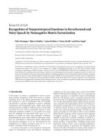
10
1
10
2
10
3
MSE
4 6 8 1012141618202224
SNR (dB)
Schmidl & Cox, A1
Proposed, A1
Schmidl & Cox, B1
Proposed, B1
Schmidl & Cox, C2
Proposed, C2
Figure 4: Timing synchronisation MSE of Schmidl and Cox
algorithm and the proposed algorithm for A1, B1, and C2 channels.
6.2. DPLL. Both sampling frequency offset estimate
M,k
and
carrier frequency offset estimate δ
f
N,k
are fed to two second-
order digital phase-locked loop (DPLL) filters whose block
diagram is presented in Figure 5.Coefficients μ
1
and μ
2
are
the proportional and integral coefficients, respectively. The
transfer function of the DPLL is [14]
H(z)
=
μ
2
(z −1) + μ
1
z −1)
2
+ μ
2
(z −1) + μ
1
=
2ζω
n
(z −1) + ω
2
n
z −1)
2
+2ζω
n
(z −1) + ω
2
n
,
(21)
where μ
2
= 2ζω
n
T
s
, μ
1
= μ
2
2
/4ζ
2
, ω
n
= 2πf
n
, T
s
is the
sampling period, ζ is the damping factor, and f
n
is the natural
frequency of the loop. In order to guarantee the stability of
the loop, the damping factor ζ and the natural frequency f
n
must satisfy the following relationship [15]:
ζ>1,
0 <ω
n
< 2,
ζω
n
<
ω
2
n
4
+1,
or
ζ
≤ 1,
0 <ω
n
< 2ζ.
(22)
From the sampling frequency offset loop output
M,k
the integer
int
and fractional part
fra
of the accumulated
sampling period error are extracted. The integer part is used
for correcting the FFT window while the fractional part is
used for correcting the subcarriers phase.
6.3. Channel Estimation. As we know, in the proposed CFO
and SPO estimation algorithms, estimation of the channel
transfer function is needed. The channel transfer function
estimate may be computed using any algorithm that gives
reliable estimates. In our design, the Zero Force (ZF) channel
M,k
μ
2
μ
1
Z
−1
Z
−1
M,k
Figure 5: Second-order digital phase-locked loop filter diagram.
estimator was applied to obtain the initial channel estimate
[16]:
H
1
(m) =
D
i
(m)Y
1
(m)
|
D
i
(m)|
2
. (23)
The symbol
D
i
(m) is the hard decision made by the
demodulator; however, when the first OFDM symbol of
the superframe is received, the symbol represents the pilot
symbol known to the receiver. After receiving the first OFDM
symbol, the estimator switches to the tracking mode. The
channel estimates are refined and tracked according to the
gradient algorithm, which minimises the mean square error
(MSE) [17]
H
k+1
(m) =
H
k
(m)+α
H
Y
k
(m) −
H
k
(m)
D
k
(m)
D
k
(m),
(24)
where α
H
is the coefficient dependent on transmitted
symbols power and is constant during the transmission.
The channel coefficients are updated every received OFDM
symbol. The author would like to stress that the channel
estimation algorithm is not an integral part of the carrier fre-
quency and sampling frequency offset estimation algorithm
and other channel estimation algorithms can be applied as
well.
7. Simulation Results
The proposed synchronisation scheme was tested for the
WINNER system parameters presented in Table 1 .The
Rayleigh fading channels were simulated using 20-path
NLOS channel models, denoted as A1, B1, and C2, with root-
mean square delay spreads τ
RMS
equal to 24.15, 94.73, and
310 nanoseconds, respectively. These models were developed
within the WINNER project for indoor/small office, typical
urban (TU) microcellular and macrocellular environments
[18]. The simulation results were obtained using 10 000
channel realisations for each SNR value.
7.1. Acquisition. As a first test, the comparison of the
accuracy of the timing synchronisation using the proposed
time metric with the 8-element synchronisation symbol
with respect to the accuracy of the Schmidl and Cox
synchronisation algorithm using 2-element synchronisation
symbol was performed. The results are presented in Figure 4.
The performance of the new metric is slightly better than the
6 EURASIP Journal on Wireless Communications and Networking
Table 1: WINNER signal parameters.
Base Coverage Urban Microcellular Indoor
Carrier frequency 3.95 GHz DL 3.95 GHz 3.95 GHz
Signal bandwidth 2
× 45 MHz 89.84 GHz 89.84 GHz
Subcarrier distance 39062.5 Hz 48828.125 Hz 48828.125Hz
Used subcarriers 1152 1840 1840
IFFT size N 2048 2048 2048
Prefix length N
G
256 200 200
Channel models C2 B1 A1
Max velocity 19.44 m/s 19.44 m/s 1.39 m/s
Packet langth 192 192 192
10
−6
10
−5
10
−4
10
−3
MSE
4 6 8 1012141618202224
SNR (dB)
Schmidl & Cox, A1
Proposed, A1
Schmidl & Cox, B1
Proposed, B1
Schmidl & Cox, C2
Proposed, C2
Figure 6: Frequency synchronisation MSE of Schmidl and Cox
algorithm and the proposed algorithm for A1, B1, and C2 channels.
performance of the latter one in all three scenarios. However,
as opposed to Schmidl and Cox method, the proposed coarse
timing synchronisation is already finished at the beginning of
the second half of the synchronisation symbol.
Results of both fractional frequency offset estimation
algorithms, obtained for three different channels, are pre-
sented in Figure 6. The algorithms performance was tested
for the frequency offsets close to the maximum frequency
offsets that the algorithms are able to estimate, that is,
0.99Δ f for Schmidl and Cox algorithm and 3.99Δ f for
the proposed solution. Although the correlation length in
the proposed algorithm is four times shorter than in the
Schmidl and Cox algorithm, the accuracy of both solutions
is almost the same, regardless of the transmission scenario.
Similar performance between the proposed solution and the
reference algorithm is achieved as a result of the averaging
of the estimates computed during the reception of the
synchronisation symbol. The comparison of the accuracy of
the algorithm with and without averaging is illustrated in
Figure 7. The averaging decreases the MSE approximately by
afactorof10forallSNRvalues.
If the frequency offset is larger than four times subcarrier
distance, an integer frequency offset estimation algorithm,
like the one described in [19]or[20], is required.
10
−6
10
−5
10
−4
10
−3
10
−2
MSE
4 6 8 1012141618202224
SNR (dB)
With averaging
Without averaging
Figure 7: Frequency synchronisation MSE with and without
averaging of the frequency offset estimate.
7.2. Tracking. During the tracking mode, randomly gen-
erated user data and pilots were mapped onto a QPSK
constellation. Loops’ parameters used by both algorithms
during simulations are shown in Ta bl e 2 .
The algorithms for the carrier frequency and sampling
frequency offsets estimation and tracking were tested for
frequency offsets of δf
= 0.01 and δf = 0.05 and
the sampling frequency offsets of δT
s
= 5 ppm and 30
ppm. The second frequency offset was chosen to be larger
than the maximum frequency offset estimation error of the
frequency synchronisation algorithm. The results of SPO
estimation are illustrated in Figures 8, 9,and10 for A1,
B1, and C2 scenarios, respectively. The mean square error
of the estimated SPO is the same in the whole used SNR
range, except for small signal power in the C2 scenario.
The influence of the channel estimator inaccuracy on the
proposed algorithm performance is visible when compared
with the results achieved for the AWGN channel only. The
mean square error floor occurs for large SNR values due to
the Rayleigh fading channel and its estimation.
Thesameerrorfloorbehaviourcanbeobservedduring
the estimation of the carrier frequency offset (see Figures 11,
12,and13). In A1 and C2 scenarios, the algorithm estimates
small δf more accurately than the larger offsets for small
EURASIP Journal on Wireless Communications and Networking 7
Table 2: DPLL loops parameters.
Channel model Algorithm
SFO DPLL CFO DPLL
ζω
n
ζω
n
A1
DD 0.20 0.20 0.40 0.50
proposed 0.30 0.20 0.40 0.50
B1
DD 0.30 0.20 0.40 0.50
proposed 0.35 0.20 0.50 0.30
C2
DD 0.23 0.44 0.40 0.50
proposed 0.23 0.44 0.30 0.50
10
−14
10
−13
10
−12
10
−11
10
−10
MSE
510152025
SNR (dB)
δT
s
= 30ppm, A1
δT
s
= 5ppm, A1
δT
s
= 30ppm, AWGN
Figure 8: The mean square error of the estimated SPO in A1
channel.
10
−14
10
−13
10
−12
10
−11
MSE
510152025
SNR (dB)
δT
s
= 30ppm, B1
δT
s
= 5ppm, B1
δT
s
= 5ppm, AWGN
Figure 9: The mean square error of the estimated SPO in B1
channel.
SNRs. However, again an MSE floor occurs for large SNR
values.
The performance of the proposed carrier frequency offset
and sampling period offset estimation algorithm was tested
for small and large velocities of the terminal with respect
to its maximum value. The simulation results, obtained for
SNR
=30 dB, δT
s
= 30 pps, and δf = 0.05, are presented
in Figure 14 for SPO estimation and in Figure 15 for CFO
10
−14
10
−13
10
−12
10
−11
10
−10
MSE
510152025
SNR (dB)
δT
s
= 30ppm, C2
δT
s
= 5ppm, C2
δT
s
= 30ppm, AWGN
Figure 10: The mean square error of the estimated SPO in C2
channel.
10
−8
10
−7
10
−6
10
−5
10
−4
MSE
510152025
SNR (dB)
δf
= 0.05 ppm, A1
δf
= 0.03 ppm, A1
δf
= 0.05 ppm, AWGN
Figure 11: The mean square error of the estimated CFO in A1
channel.
estimation. The mean square error of the offset estimation
degrades rapidly with the low but increasing velocity of the
terminal. The degradation slows down for velocities larger
than 10 m/s. On average, an increase of the velocity by 10 m/s
in B1 and C2 scenarios increases the MSE of the estimated
SPO and CFO approximately by a factor of 1.5. An increase
of the velocity by 1 m/s in A1 scenario increases the MSE of
the estimated SPO and CFO by a factor of 1.2.
8 EURASIP Journal on Wireless Communications and Networking
10
−8
10
−7
10
−6
10
−5
MSE
510152025
SNR (dB)
δf
= 0.05 ppm, B1
δf
= 0.03 ppm, B1
δf
= 0.05 ppm, AWGN
Figure 12: The mean square error of the estimated CFO in B1
channel.
10
−7
10
−6
10
−5
10
−4
MSE
510152025
SNR (dB)
δf
= 0.05 ppm, C2
δf
= 0.03 ppm, C2
δf
= 0.05 ppm, AWGN
Figure 13: The mean square error of the estimated CFO in C2
channel.
10
−14
10
−13
10
−12
10
−11
10
−10
MSE
0 5 10 15 20 25 30
v (m/s)
A1
B1
C2
10
−13
10
−12
01234
Figure 14: The mean square error of the estimated SPO for different
values of mobile velocity.
10
−7
10
−6
10
−5
10
−4
MSE
0 5 10 15 20 25 30
v (m/s)
A1
B1
C2
10
−7
10
−6
01234
Figure 15: The mean square error of the estimated CFO for
different values of mobile velocity.
10
−14
10
−13
10
−12
10
−11
10
−10
10
−9
MSE
5 10152025
SNR (dB)
Proposed algorithm, A1
Decision-directed algorithm, A1
Proposed algorithm, B1
Decision-directed algorithm, B1
Proposed algorithm, C2
Decision-directed algorithm, C2
Figure 16: The mean square error of the estimated SFO for δT
s
=
30 ppm.
Finally, both algorithms, that is, the proposed and
decision-directed algorithms, are compared in all scenarios
for a sampling period offset of δT
s
= 30 ppm and a CFO
of δf
= 0.05. However, as with to the proposed solution,
carrier frequency and sampling period offsets estimated by
the DD algorithm were filtered using the second-order DPLL.
Both solutions used the same sets of subcarrier indices
C
1
and C
2
. The results plotted in Figures 16 and 17 indicate
that for low SNR values the proposed algorithm copes better
with severe channel conditions than the decision-directed
one, especially in A1 and C2 scenarios. Poor performance of
the DD algorithm is related to the increase of the channel
estimate phase error due to the hard decisions made by the
data demodulator and propagation of the phase error to the
phase-difference-dependent signal (9). Because the proposed
solution does not use hard decisions, the phase errors of
EURASIP Journal on Wireless Communications and Networking 9
10
−7
10
−6
10
−5
10
−4
10
−3
10
−2
MSE
510152025
SNR (dB)
Proposed algorithm, A1
Decision-directed algorithm, A1
Proposed algorithm, B1
Decision-directed algorithm, B1
Proposed algorithm, C2
Decision-directed algorithm, C2
Figure 17: The mean square error of the estimated CFO for δf =
0.05.
the erroneous channel estimates are not amplified, and their
influence on the overall algorithm performance is smaller
than in the DD algorithm.
8. Conclusions
In this paper, link-level synchronisation algorithms designed
for the OFDM-based proposal for 4G system developed in
the WINNER project have been introduced. A new time
metric and pilot symbol design for coarse timing synchro-
nisation, as well as new carrier and sampling frequency offset
estimation algorithms, were proposed. The algorithms were
tested in three different transmission scenarios. Simulation
results showed that on the basis of only one OFDM symbol,
the algorithms, at the cost of moderate complexity, gave
accurate time and frequency offset estimates. The carrier and
sampling frequency offset estimation and tracking algorithm,
based on the channel estimates, is suitable for transmission
systems with low pilot overhead. Simulation results showed
that for low SNR, the proposed algorithm works better than
the decision-directed solution.
References
[1] “D2.10: Final report on identified RI key technologies,
system concept, and their assessment,” Tech. Rep. IST-2003-
507581, Information Society Technologies, Yerevan, Armenia,
December 2005.
[2] M. Abaii, G. Auer, Y. Cho, et al., “D6.13.7 Test Scenarios
and Calibration Cases Issue 2,” Tech. Rep. IST-4-027756
WINNER II, Information Society Technologies, Yerevan,
Armenia, December 2006.
[3] J J. van de Beek, M. Sandell, and P. O. B
¨
orjesson, “ML
estimation of time and frequency offset in OFDM systems,”
IEEE Transactions on Signal Processing, vol. 45, no. 7, pp. 1800–
1805, 1997.
[4]T.M.SchmidlandD.C.Cox,“Robustfrequencyand
timing synchronization for OFDM,” IEEE Transactions on
Communications, vol. 45, no. 12, pp. 1613–1621, 1997.
[5] F. Tufvesson, O. Edfors, and M. Faulkner, “Time and frequency
synchronization for OFDM using PN-sequence preambles,” in
Proceedings of the 50th IEEE Vehicular Technology Conference
(VTC ’99), vol. 4, pp. 2203–2207, Amsterdam, The Nether-
lands, September 1999.
[6] C. Yan, J. Fang, Y. Tang, S. Li, and Y. Li, “OFDM synchroniza-
tion using PN sequence and performance,” in Proceedings of
the 14th IEEE International Symposium on Personal, Indoor and
Mobile Radio Communications (PIMRC ’03), vol. 1, pp. 936–
939, Beijing, China, September 2003.
[7] D.K.Kim,S.H.Do,H.B.Cho,H.J.Chol,andK.B.Kim,“A
new joint algorithm of symbol timing recovery and sampling
clock adjustment for OFDM systems,” IEEE Transactions on
Consumer Electronics, vol. 44, no. 3, pp. 1142–1149, 1998.
[8] S. A. Fechtel, “OFDM carrier and sampling frequency syn-
chronization and its performance on stationary and mobile
channels,” IEEE Transactions on Consumer Electronics, vol. 46,
no. 3, pp. 438–441, 2000.
[9] K. Shi, E. Serpedin, and P. Ciblat, “Decision-directed fine
synchronization in OFDM systems,” IEEE Transactions on
Communications, vol. 53, no. 3, pp. 408–412, 2005.
[10] B. Yang, K. B. Letaief, R. S. Cheng, and Z. Cao, “Timing
recovery for OFDM transmission,” IEEE Journal on Selected
Areas in Communications, vol. 18, no. 11, pp. 2278–2291, 2000.
[11] D. Aronsson, G. Auer, S. Bittner, et al., “Link level procedures
for the WINNER System,” Tech. Rep. IST-4-027756 WIN-
NER II, Information Society Technologies, Yerevan, Armenia,
November 2007.
[12] P. H. Moose, “Technique for orthogonal frequency division
multiplexing frequency offset correction,” IEEE Transactions
on Communications, vol. 42, no. 10, pp. 2908–2914, 1994.
[13] M. Luise and R. Reggiannini, “Carrier frequency acquisition
and tracking for OFDM systems,” IEEE Transactions on
Communications, vol. 44, no. 11, pp. 1590–1598, 1996.
[14] F. M. Gardner, Phaselock Techniques, John Wiley & Sons, New
York, NY, USA, 2005.
[15] Z W. Zheng, Z X. Yang, C Y. Pan, and Y S. Zhu, “Novel
synchronization for TDS-OFDM-based digital television ter-
restrial broadcast systems,” IEEE Transactions on Broadcasting,
vol. 50, no. 2, pp. 148–153, 2004.
[16] J. Proakis, Digital Communications, McGraw-Hill, New York,
NY, USA, 4th edition, 2001.
[17] A. Langowski, A. Piatyszek, Z. Długaszewski, and K.
Wesołowski, “VHDL realisation of the channel estimator and
the equaliser in the OFDM receiver,” in Proceedings of the 10th
National Symposium of Radio Science (URSI ’02), pp. 129–134,
Poznan, Poland, March 2002.
[18] “D5.4 Final Report on Link Level and System Level Channel
Models,” Tech. Rep. IST-2003-507581 WINNER, Information
Society Technologies, Yerevan, Armenia, September 2005.
[19] K. Bang, N. Cho, J. Cho, et al., “A coarse frequency offset
estimation in an OFDM system using the concept of the
coherence phase bandwidth,” IEEE Transactions on Commu-
nications, vol. 49, no. 8, pp. 1320–1324, 2001.
[20] Z. Długaszewski and K. Wesołowski, “Simple coarse frequency
offset estimation schemes for OFDM burst transmission,” in
Proceedings of the 13th IEEE International Symposium on Per-
sonal, Indoor and Mobile Radio Communications (PIMRC ’02),
vol. 2, pp. 567–571, Lisbon, Portugal, September 2002.