Báo cáo hóa học: "Research Article Advanced Receiver Design for Quadrature OFDMA Systems" doc
Bạn đang xem bản rút gọn của tài liệu. Xem và tải ngay bản đầy đủ của tài liệu tại đây (808.79 KB, 9 trang )
Hindawi Publishing Corporation
EURASIP Journal on Wireless Communications and Networking
Volume 2009, Article ID 953018, 9 pages
doi:10.1155/2009/953018
Research Article
Advanced Receiver Design for Quadrature OFDMA Systems
Lin Luo,
1, 2
Jian (Andrew) Zhang,
1, 2
and Zhenning Shi
1, 2
1
Department of Information Engineering, the Australian National University, Canberra, ACT 0200, Australia
2
Canberra Research Laboratory, National ICT Australia (NICTA), Canberra, ACT 2601, Australia
Correspondence should be addressed to Lin Luo,
Received 1 August 2008; Revised 24 December 2008; Accepted 24 January 2009
Recommended by Yan Zhang
Quadrature orthogonal frequency division multiple access (Q-OFDMA) systems have been recently proposed to reduce the peak-
to-average power ratio (PAPR) and complexity, and improve carrier frequency offset (CFO) robustness and frequency diversity for
the conventional OFDMA systems. However, Q-OFDMA receiver obtains frequency diversity at the cost of noise enhancement,
which results in Q-OFDMA systems achieving better performance than OFDMA only in the higher signal-to-noise ratio (SNR)
range. In this paper, we investigate various detection techniques such as linear zero forcing (ZF) equalization, minimum mean
square error (MMSE) equalization, decision feedback equalization (DFE), and turbo joint channel estimation and detection, for
Q-OFDMA systems to mitigate the noise enhancement effect and improve the bit error ratio (BER) performance. It is shown that
advanced detections, for example, DFE and turbo receiver, can significantly improve the performance of Q-OFDMA.
Copyright © 2009 Lin Luo et al. This is an open access article distributed under the Creative Commons Attribution License, which
permits unrestricted use, distribution, and reproduction in any medium, provided the original work is properly cited.
1. Introduction
Future broadband wireless communication systems require
high-speed data rate transmissions through severe multipath
wireless channels. As an effective antimultipath multiple
access scheme, orthogonal frequency division multiple access
(OFDMA) is endorsed by leading standards such as HIPER-
LAN/2, IEEE802.11, and IEEE802.16 and downlink in the
3GPP long-term evolution (LTE). Nevertheless, to support
a number of users’ access, the number of subcarriers, N,
in OFDMA systems is usually very large, which provides
flexibility and high spectrum efficiency, at the expense
of high complexity, severe PAPR, and sensitivity to CFO
in general. Alternatively, single-carrier transmission with
cyclic prefix (CP) is a closely related transmission scheme,
which significantly reduces PAPR and CFO sensitivity, with
the same multipath interference mitigation property as
OFDM [1, 2]. As an extension of the single carrier with
frequency domain equalization (SC-FDE) [2]toaccom-
modate multiuser access, single-carrier frequency division
multiple access (SC-FDMA) [3] is adopted as the uplink
multiple access scheme in 3GPP LTE. However, noise
enhancement and higher complexity introduced by discrete
Fourier transform (DFT) spreading and inverse DFT (IDFT)
despreading limited the applications of SC-FDMA. More
importantly, from the viewpoint of user end (UE), usable
and legal resource blocks of subcarriers are limited, therefore
the complete FFT/IFFT computation for OFDMA and SC-
FDMA demodulations is not necessary especially under the
low-power consideration of the battery-driven handsets.
The Quadrature OFDMA (Q-OFDMA) systems [4]
overcome the aforementioned problems with improved
performance and reduced complexity. Based on the concept
of layered fast Fourier transform (FFT) structure [4], the
intermediate domain is introduced and a Q-OFDMA system
has multiple small-size inverses (IFFTs) in the transmitter,
which results in a loss of the subcarrier orthogonality. While
at receiver, the orthogonality is recovered by FFT operations.
In terms of minimizing the bit error ratio (BER), the
optimum maximum likelihood (ML) [5]detectorisable
to utilize both the diversity and coding gain furnished
by frequency-selective fading channels. However, in most
practical systems, linear equalizer (LE) [5–7]anddecision
feedback equalizer (DFE) [5–9] have been designed for
complexity reasons. Turbo equalization [10–13]hasbeen
extensively studied when signal-to-noise ratio (SNR) and
channel impulse response (CIR) are precisely known to the
receiver. In cases where such information is not available or
2 EURASIP Journal on Wireless Communications and Networking
time varying thus need to be tracked, channel information
should be estimated. Methods [14–16] attempt to perform
estimation and equalization jointly, which improve the
system performance at the cost of intractable complexity.
From the BER performance analysis of Q-OFDMA
systems [17] we find that the essential characteristics of the
Q-OFDMA systems. When linear zero forcing (ZF) equalizer
is employed, there is a tradeoff between noise enhancement,
error propagation, and frequency diversity gain, by setting
different value of P. When SNR is small, Q-OFDMA systems
with smaller P have better BER performance; while with SNR
increasing, Q-OFDMA systems with larger P will become
superior. The exact SNR point where one system starts to
outperform the other depends on the channel condition and
modulation scheme [4]. As a special case of P
= 1, the Q-
OFDMA system becomes the conventional OFDMA system,
which outperforms the Q-OFDMA system (1 <P<N)only
in low SNR range. This problem can be solved by utilizing
advanced receivers, which is the motivation of this paper.
When linear minimum mean square error (MMSE) equalizer
is used, for BPSK modulated signals, Q-OFDMA system is
always better than OFDMA system with ZF equalizer (for
conventional OFDMA systems, ZF is already the maximum
likelihood solution and MMSE equalizer cannot achieve
better BER performance [18]). Other advanced equalizers,
such as decision feedback equalizer and iterative equalizers
can efficiently improve the performance of Q-OFDMA
system, whose complexity is similar to that of the linear
equalized OFDMA/SC-FDMA systems.
In this paper, we focus on analyzing the various detection
techniques for Q-OFDMA systems, including ZF and MMSE
LEs, DFE, and iterative equalization. The rest of this paper
is organized as follows. In Section 2, Q-OFDMA system
based on the layered FFT structure is presented. We present
signal detection and decoding techniques for Q-OFDMA
and analyze the performance in Section 3. Finally, we
demonstrate the performance of Q-OFDMA systems using
various detection techniques by simulations in Section 4.
The following notations will be used throughout the
paper. Matrices and vectors are denoted by symbols in bold
face, x
i,j
indicates the (i, j)th element of a matrix X,andx(i)
indicates the element i in a vector x.Tr[
·] denotes the trace
of a matrix, E[
·] denotes the expectation, |·| and · denote
the absolute value and estimated value, respectively. and
denote the circular convolution and element-wise product
of two vectors, respectively. (
·)
−1
,(·)
T
and (·)
H
represent
inverse, transpose, and Hermitian conjugate. x,
˘
x,and
x
denote symbol x in time domain, intermediate domain, and
frequency domain, separately.
2. Q-OFDMA System Model
To compare the Q-OFDMA with the well-known OFDMA
and SC-FDMA systems, Figure 1 shows the intuitionistic
difference of the core baseband modules among three
systems. At the transmitter, each user’s data is first encoded,
interleaved, and mapped to a certain constellation. Unlike
the subchannel in conventional OFDMA systems, which is
defined in the one-dimension frequency domain, subchan-
nels in Q-OFDMA systems are defined over an array of two
dimensions in the intermediate domain [4]. This array is
P
× Q, where both P and Q are powers of 2, and N = PQ is
the equivalent to the total number of subcarriers in ordinary
OFDMA systems. Thanks to the judicious use of divide-and-
conquer approach in the computation of DFT [5], smaller
size of IFFTs/FFTs are utilized in the transmitter/receiver of
Q-OFDMA, which results in reduced complexity and PAPR.
Given three N-point time-domain symbols x, h,and
their circular convolution output y
= x h, their DFTs have
the relationship
y =
√
Nx
h. If we rearrange the frequency
domain symbols
x,
h,andy into P × Q matrices (PQ = N)
row-wise according to the layered IFFT structure concept, the
vectors
x
q
,
h
q
,andy
q
from the qth column of the matrices
retain that
y
q
=
√
Nx
q
h
q
, where [y
q
]
p
= y(pQ + q),
[
x
q
]
p
= x(pQ+q), [
h
q
]
p
=
h(pQ+q), and p = 0, 1, ,P−1.
Define the intermediate-domain symbols
{
˘
x
q
,
˘
h
q
,
˘
y
q
} as
the IDFTs of
{x
q
,
h
q
, y
q
},givenby
˘
x
q
= F
H
P
x
q
,
˘
h
q
= F
H
P
h
q
,
˘
y
q
= F
H
P
y
q
,(1)
where F
H
P
is the normalized P-point IDFT matrix. According
to the convolution property of DFT, we get
˘
y
q
=
Q
˘
x
q
˘
h
q
, which establishes the relationship of the symbols in the
intermediate domain, and can be expressed in matrix form
as
˘
y
q
=
Q
˘
H
q
˘
x
q
,(2)
where the P
×P circulant matrix
˘
H
q
represents the dispersive
channel, with [
˘
H
q
]
i,j
=
˘
h(((i
− j)mod P)Q + q), where
˘
h(·)
denotes the channel response in the intermediate domain.
At the receiver of the Q-OFDMA system, in order to
realize a one-tap equalization, the weighting outputs are
transformed from the intermediate domain to frequency
domain as
y
q
= F
P
˘
y
q
=
ND
q
F
P
˘
x
q
+ F
P
˘
n
q
,(3)
where
˘
n
q
∼N (0, N
0
) are additive white Gaussian noise
(AWGN) samples, the symbol energy of modulation symbols
˘
x
q
is E
s
,and
D
q
=
F
P
˘
H
q
F
H
P
√
P
= diag(
h
q
)(4)
indicates the diagonalized channel matrix. This scheme
recovers the orthogonality between subcarriers in the fre-
quency domain to allow for a simple one-tap equalization,
similar to that for conventional OFDMA systems.
An interesting observation is that (3) actually resembles
to the results obtained in precoded OFDMA systems [18],
with a precoding matrix F
P
. Thus, frequency diversity can
be achieved without introducing any complexity relating to
precoders in the transmitter, and PAPR is reduced as well.
EURASIP Journal on Wireless Communications and Networking 3
Q-OFDMA
Subchannel
assignment
PQ-pt
IFFTs
Inter-
leaving
P/S &
add CP
Channel
Remove
CP & S/P
PQ-pt
FFTs
Subchannel
collection
Equali-
zation
Detect
OFDMA
Subchannel
assignment
N-pt
IFFT
P/S &
add CP
Channel
Remove
CP & S/P
N-pt
FFT
Subchannel
collection
Equali-
zation
Detect
SC-FDMA
P-pt
FFT
Subchannel
assignment
N-pt
IFFT
P/S &
add CP
Channel
Remove
CP & S/P
N-pt
FFT
Subchannel
collection
Equali-
zation
P-pt
IFFT
Detect
Figure 1: System structure comparison.
3. Signal Detection
In this section, we will present techniques for signal detec-
tion, including ZF and MMSE equalizers, DFE and turbo
receiver, specially for Q-OFDMA systems.
3.1. Low-Complexity Linear Detections. The simplest detec-
tion is ZF equalization, and the subchannel signal
˘
x
q
can be
calculated as
˘
x
q
=
F
H
P
D
−1
q
F
P
˘
y
q
√
N
,(5)
which leads to the average BER for a Q-OFDMA system with
M-ary QAM modulation as [17]
(Pe)
ZF
=
4(1 − 1/
√
M)
Q log
2
M
Q−1
q=0
Q
⎛
⎝
(3/(M −1))γ
(1/P)
P−1
p
=0
|
h
p,q
|
−2
⎞
⎠
,
(6)
where γ
= E
s
/N
0
, |
h
p,q
|=|
h
pQ+q
| and Q(x) =
+∞
x
exp(−
t
2
/2)dt/
√
2π.From(6) we can see, similar to those in single-
carrier systems [2], any small channel coefficient
h
pQ+q
leads
to noise enhancement and error propagation in a group
of P subcarriers. On the other hand, frequency diversity is
improved by averaging channel power over the same group
of subcarriers.
Another low-complexity alternative, MMSE equalizer,
can efficiently solve these problems. Similar to that in
conversional OFDMA systems, the MMSE equalizer for
Q-OFDMA incurs a marginal increase in complexity by
requiring the estimation of noise variance σ
2
n
, and is given
by
˘
x
q
=
F
H
P
D
H
q
D
H
q
D
q
+ γ
−1
I
−1
F
P
˘
y
q
√
N
,(7)
where γ
= E
s
/N
0
,andI is an identity matrix.
3.2. Decision Feedback Detection. The class of decision-
directed detectors improve the system performance on the
cost of complexity. Current DFE techniques can be operated
in the time domain [5], frequency domain [9], or with hybrid
structure [7, 8], where the feedforward filter is realized in
the frequency domain, while the feedback filter is realized
in the time domain. Similar to the time-domain DFE (TD-
DFE), the hybrid-domain DFE (HD-DFE) is affected by the
precursors of the intersymbol interference (ISI) and error
propagation. Since both the signal processing and the filter
design are performed entirely in the frequency domain, the
frequency-domain DFE (FD-DFE) only requires a quarter
of the complexity of the HD-DFE, whose complexity is
half of that of the TD-DFE [9]. Regarding to the work of
DFE presented in this paper, our main contribution lies
in extending the general DFE concept to the Q-OFDMA
systems and testing its performance, instead of proposing
new DFE structure.
Applied to the signal represented in (3), the block DFE,
as shown in Figure 2, can be realized with HD-DFE and FD-
DFE. The block FD-DFE, as shown in Figure 2(b),canbe
described by the following equations:
α = AF
P
˘
y
q
=
NAD
q
F
P
˘
x
q
+ AF
P
˘
n
q
,
x
q
= α −BF
P
x
q
,
˘
x
q
= T
F
H
P
x
q
,
(8)
where the feedforward and feedback filters, A and B,
respectively, are chosen to minimize the mean square error
(MSE) and whiten the noise at the input of the decision
device T (
·). Since we can only feedback decisions in a causal
fashion, B is usually chosen to be a strictly upper or lower
triangular matrix with zero diagonal entries. The matrices
A and B are designed according to MMSE criteria. When
B is chosen to be triangular and the MSE between the
block estimate before the decision device is minimized, the
feedforward and feedback filters can be expressed as [19]
U
H
ΛU = R
−1
˘
x
+ F
H
P
D
H
q
F
P
R
˘
n
F
H
P
−1
D
q
F
P
,
(9a)
G
mmse
= R
˘
x
F
H
P
D
H
q
F
P
R
˘
n
F
H
P
+ D
q
F
P
R
˘
x
F
H
P
D
H
q
−1
,(9b)
A
= F
P
UG
mmse
,
(9c)
B
= F
P
(U −I)F
H
P
,
(9d)
where we assume the autocorrelation matrices R
˘
x
and R
˘
n
are
known, (9a) is obtained using Cholesky decomposition, U
is an upper triangular with unit diagonal, Λ is a diagonal
matrix, and for simplicity, the factor
√
N is absorbed in D
q
.
4 EURASIP Journal on Wireless Communications and Networking
˘
y
q
y
q
α
˘
α
+
−
˘
x
q
˘
x
q
P-point
FFT
Feedforward
filter A
P-point
IFFT
Decision
device
Feedback
filter B
(a)
˘
y
q
y
q
α
x
q
+
−
˘
x
q
˘
x
q
P-point
FFT
Feedforward
filter A
P-point
IFFT
Decision
device
Feedback
filter B
P-point
FFT
(b)
Figure 2: Decision feedback detector for Q-OFDMA systems: (a) hybrid domain DFE, and (b) frequency domain DFE.
Decoder
Deinter-
leaver
Demodu-
lator
P-point
IFFT
MMSE
equalizer
P-point
FFT
Channel
estimator
P-point
FFT
ModulatorInterleaver
b
(k)
m
L
E
c
(k)
n
L
e
E
d
(k)
n
L
E
d
(k)
n
+
−
L
D
c
(k)
n
L
e
D
c
(k)
n
L
D
d
(k)
n
˘
x
(k)
ζ
i
y
(k)
ζ
i
˘
y
(k)
ζ
i
E
˘
x
(k)
ζ
i
Cov
˘
x
(k)
ζ
i
,
˘
x
(k)
ζ
i
H
(k)
+
−
Figure 3: The turbo receiver for Q-OFDMA systems.
Since DFE takes into account the finite-alphabet property
of the information symbols and the decision feedback filter
eliminates the intersymbol interference from previously
detected symbols, the performance of DFE is usually better
than linear detectors, especially at moderate high SNR values,
where decision errors are less likely to propagate.
3.3. Turbo Detection with Soft Interference Cancellation. In
this section, as shown in Figure 3, we propose an iterative
receiver for joint estimation, equalization, and decoding
for the Q-OFDMA systems based on the turbo processing
principle. The estimator makes use of training symbols
and the soft-decoded data information to track the channel
frequency response. The equalizer can use the re-estimated
channel to detect the transmitted data iteratively until the
satisfactory outcome is obtained. We can judiciously choose
estimation, equalization, and decoding algorithms according
to the performance/complexity tradeoff.
For the pth element of
y,werewrite(3)as
y(p) = (DF
P
)
p,p
˘
x(p)+
k
/
= p
(DF
P
)
p,k
˘
x(k)+F
P
˘
n(p). (10)
From (10), we can see the precoding matrix F
P
breaks the
orthogonal character of D and introduces ISI, which can be
eliminated by the following turbo equalization.
The equalizer gives the MMSE estimates
˘
x of
˘
x based on
the received signal
y and the a priori information of
˘
x, that
is, E(
˘
x)andCov(
˘
x,
˘
x). After passing through a demapping
module, the extrinsic information for each coded bit is
delivered as [11]
L
e
E
(d
n
) = ln
P
˘
x(p)
| d
n
= 1
P
˘
x(p)
| d
n
= 0
(11)
= ln
∀d:d
n
=1
P(
˘
x(p)
| d)
∀n
:n
/
=n
P(d
n
)
∀d:d
n
=0
P(
˘
x(p)
| d)
∀n
:n
/
=n
P(d
n
)
(12)
= ln
P
d
n
= 1 |
˘
x(p)
P
d
n
= 0 |
˘
x(p)
L
E
(d
n
)
−ln
P(d
n
= 1)
P(d
n
= 0)
L
D
(d
n
)
.
(13)
As we can see in Figure 3, the output of the demodulator,
L
E
(d
n
), has been defined as the a posteriori log-likelihood
ratio (LLR) of the coded bit d
n
, and the output of the
interleaver, L
D
(d
n
), as the a priori LLR of d
n
. The extrinsic
information, L
e
E
(d
n
), is a function of
˘
x(p) and the a priori
information about the coded bits other than the nth bit, that
is, L
D
(d
n
), n
/
=n, from the previous iteration. For the initial
equalization stage, no a priori information is available and
hence we have L
D
(d
n
) = 0,∀n. The extrinsic information
L
e
E
(d
n
), which is independent of L
D
(d
n
), is deinterleaved
EURASIP Journal on Wireless Communications and Networking 5
and fed into the decoder as the a priori information for
the decoder. Based on the a priori LLR L
E
(c
n
), the decoder
provides the a posteriori LLR of each coded bit as follows:
L
e
D
(c
n
) = ln
P
{
L
E
(c
n
)}|c
n
= 1
P
{
L
E
(c
n
)}|c
n
= 0
=
ln
P
c
n
= 1 |{L
E
(c
n
)}
P
c
n
= 0 |{L
E
(c
n
)}
L
D
(c
n
)
−ln
P(c
n
= 1)
P(c
n
= 0)
L
E
(c
n
)
.
(14)
At the last iteration, a hard decision is made as
b
m
= arg max
b∈{0,1}
P
b
m
= b |{L
E
(c
n
)}
. (15)
Here, the interleaver/deinterleaver module shuffles
coded bits to decorrelate errors introduced by the
decoder/equalizer, and assure, locally in several iterations, d
n
are independent and L
D
(d
n
) are true a priori information on
the d
n
, which make the iterative error correction possible.
3.3.1. MMSE Criteria. To perform MMSE estimation, we
require the statistics
˘
x(p) E[
˘
x(p)] and
˘
v(p)
Cov[
˘
x(p),
˘
x(p)] of the symbols
˘
x(p), which can be computed
by the a priori LLR of the coded bits, L
D
(d
n
). For simplicity,
we assume BPSK modulation is used in the following
analysis. The soft estimates and their variance are defined as
[11]
˘
x(p)
= tanh
L
D
(d
n
)
2
,
(16)
˘
v(p)
= 1 −
˘
x(p)
2
.
(17)
Define
˘
x
p
=
˘
x(1), ,
˘
x(p
−1), 0,
˘
x(p +1), ,
˘
x(P)
T
,
˘
V
p
= Diag
˘
v(1), ,
˘
v(p
−1), 1,
˘
v(p +1), ,
˘
v(P)
,
(18)
a soft interference cancellation is performed on
y to obtain
˘
s
y − DF
P
˘
x
= DF
P
(
˘
x −
˘
x)+F
P
˘
n,
(19)
which then be fed into a linear MMSE filter and we get
˘
z(p) w
H
p
˘
s(p), (20)
where the filter w
p
is chosen to minimize the MSE between
the coded bit
˘
x and the filter output
˘
z, that is,
w
p
= arg min E{
˘
x
−
˘
z
2
}
=
Cov[y, y]
−1
Cov[
˘
x, y]
=
σ
2
˘
n
I + DF
P
˘
V
p
(DF
P
)
H
−1
DF
P
ε
p
=
σ
2
˘
n
I + DF
P
˘
V(DF
P
)
H
+(1−
˘
v(p))DF
P
ε
p
(DF
P
ε
p
)
H
−1
DF
P
ε
p
,
(21)
where ε
p
is a column vector whose P elements are all zeros
except the pth element which is one. Thus, the MMSE
estimate
˘
x of
˘
x can be given by [11]
˘
x(p)
=
˘
x(p)+
˘
z(p). (22)
We a pp ly (19)to(22) and formulate the MMSE estimate as
˘
x(p)
=
˘
x(p)+w
H
p
(y −DF
P
˘
x)
= w
H
p
y −DF
P
˘
x +
˘
x(p)DF
P
ε
p
,
(23)
whose statistics mean μ
˘
x
(p),
˘
x ∈ B (for BPSK, B =
{
+1, −1}), and variance σ
2
˘
x
(p)arecomputedas
μ
˘
x
(p) = w
H
p
E[y |
˘
x(p)
=
˘
x]
−DF
P
˘
x +
˘
x(p)DF
P
ε
p
=
˘
xw
H
p
DF
P
ε
p
,
σ
2
˘
x
(p) = E
˘
x(p)
−μ
˘
x
(p)
2
=
w
H
p
DF
P
ε
p
1 − (DF
P
ε
p
)
H
w
p
.
(24)
Thus, the output extrinsic LLR L
e
E
(d
n
)(11) of the equalizer,
is given by
L
e
E
(d
n
) = ln
P
˘
x(p)
| d
n
= 1
P
˘
x(p)
| d
n
= 0
=
ln
P
˘
x(p)
|
˘
x(p)
= +1
P
˘
x(p)
|
˘
x(p)
=−1
=
2
˘
x(p)μ
˘
x
=+1
(p))
σ
2
˘
x
=+1
(p)
=
2w
H
p
y −DF
P
˘
x +
˘
x(p)DF
P
ε
p
1 − (DF
P
ε
p
)
H
w
p
.
(25)
For the initial iteration, we have L
D
(d
n
) = 0, ∀n,
˘
x(p)
=
0and
˘
v(p) = 1∀p, then the MMSE linear equalizer solution
is simplified to
w
p
=
σ
2
˘
n
I + DD
H
−1
DF
P
ε
p
, (26)
and the corresponding MMSE output and LLR are given by
˘
x(p)
=
w
p
H
y,
L
e
E
(d
n
) =
2
w
p
H
y
1 − (DF
P
ε
p
)
H
w
p
.
(27)
For alleviating the high complexity of computing w
p
for
each iteration, in the first several iterations, we utilize the
coefficient matrix w
p
for the first iteration to compute
˘
x(p)
and L
e
E
(d
n
) according to (27).
In the following iterations, approximately perfect a priori
LLR
|L
D
(d
n
)|→∞, ∀n is available, which leads to
˘
x
p
=
(
˘
x(1), ,
˘
x(p−1), 0,
˘
x(p+1), ,
˘
x(P))
T
,and
˘
v(p) = 0, ∀p.
w
p
is then simplified to
w
p
=
σ
2
˘
n
I + DF
P
ε
p
(DF
P
ε
p
)
H
−1
DF
P
ε
p
,
=
DF
P
ε
p
σ
2
˘
n
+(DF
P
ε
p
)
H
DF
P
ε
p
.
(28)
6 EURASIP Journal on Wireless Communications and Networking
Table 1: System receiver complexity in terms of numbers of complex multiplications per frame. For the Q-OFDMA systems, the linear
MMSE equalizer, FD-DFE, and turbo receiver (the complexity of the decoder is excluded, i denotes the number of the iterations) are listed
for comparison. For the conventional OFDMA system, only the maximum likelihood solution, linear ZF equalizer, is compared. For SC-
FDMA system, the linear MMSE equalizer, which reduces the effect of the noise enhancement, is compared. For the example scenario,
numerical values are for N
= 1024, Q = 16, P = 64, and M = 1.
System Equalizer Complexity Example
Q-OFDMA
MMSE N/2log
2
Q + MP log
2
P +2MP 2560
FD-DFE N/2log
2
Q +2MP log
2
P +3MP 3008
Turb o N/2log
2
Q + i(4MP + MP log
2
P) −MP
3264 (i
= 2)
5184 (i
= 5)
OFDMA ZF N/2log
2
N + MP 5184
SC-FDMA MMSE N/2log
2
N + MP + P/2log
2
P 5376
3.3.2. Matched Filter Criteria. Analyze (26), we find in the
first iteration, channel D which is estimated based on the
training sequence, may not be reliable. In order to reduce the
complexity, the operator of matrix inverse can be bypassed
by replacing MMSE equalizer with an approximate matched
filter as [20]
w
p
=
DF
P
ε
p
σ
2
˘
n
+Tr[DD
H
]
. (29)
3.3.3. Turbo Channel Estimation. As a result of (3), chan-
nel estimation can be easily implemented by transmitting
carefully chosen training symbols
˘
x
tr
such that each element
in F
P
˘
x
tr
has unity magnitude. However, the estimation
based on training symbols may not be reliable, especially
when the channel is time varying and channel tracking is
needed. In this section, we propose an iterative channel
estimation technique in conjunction with data detection.
The idea is to firstly use training symbols to perform an
initial estimation, then the soft data information delivered by
decoder will be utilized in estimation. At last iteration, when
the decoding information from decoder becomes reliable,
advanced estimators, that is, maximum likelihood or MMSE
estimator, are employed to provide further performance
improvement.
From (4), we can see DF
P
= F
P
˘
H,whichisafrequency
response of channel. Therefore, we can use
H = DF
P
as
the channel estimates for Q-OFDMA systems. The channel
estimation method is summarized as the following several
steps:
(1) Initial channel estimation
H
p,p
1
=
y(p)
˘
x
T
(p)
=
H
p,p
+ Δ
T
(p), (30)
where
˘
x
T
(p) is the training symbols, Δ
T
(p)isAWGN
with zero mean and variance (σ
2
n
+ σ
2
ISI
). Once the
initial channel estimates are obtained, the detected
soft data symbols
˘
x are achieved by (16) for BPSK
modulation.
(2) Iterative channel estimation. In this stage, data-aided
LS channel estimation is utilized;
H
p,p
2
=
y(p)
˘
x(p)
=
H
p,p
+ Δ(p). (31)
Similar to the initial estimation stage, it can be shown
that Δ(p) has zero mean and variance (σ
2
n
+ σ
2
ISI
).
(3) Final channel estimation. In the last iteration, the
decoding information from decoder becomes very
reliable, MMSE estimator [5]isabletoprovide
further performance improvement.
3.4. Complexity Analysis. Complexity is defined as the num-
ber of complex multiplications required in processing each
frame. FFT complexity is based on radix-2 algorithm, which
means the computational complexity for N point FFT/IFFT
is O(N/2log
2
N). Assume user-k occupies M subchannels
in Q-OFDMA systems, and equivalently, MP subcarriers in
conventional OFDMA systems.
With a linear equalizer, a general OFDMA receiver
includes an N-point FFT and a one-tap equalizer, and the
complexity is N/2log
2
N + MP.ForaSC-FDMAreceiver,
refer to Figure 1,anextrap-point IFFT is required based on
the OFDMA receiver, thus the complexity is N/2log
2
N +
MP + P/2log
2
P. For a Q-OFDMA system, the receiver
includes PQ-point FFTs, MP-point IFFTs, MP-point weight-
ing operators, and M one-tap equalizer. The complexity is
N/2log
2
Q+MP log
2
P+2MP. When the channels change, the
computational complexity of linear ZF/MMSE equalizer is
O(P
3
) for Q-OFDMA systems, and O(N
3
) for OFDMA/SC-
FDMA systems, where N equals to Q (Q
≥ 1) times of P.
From Tabl e 1 , we note that the receiver of the Q-OFDMA
with linear equalizer only requires half of the complexity of
the OFDMA, whose complexity is similar to the SC-FDMA
system.
The complexity of decision feedback detection is com-
parable to that of linear detectors, because the feedforward
and feedback filters only have matrix-vector multiplications.
Additionally, an FD-FDE equalizer in Figure 2(b) needs an
extra P-point FFT for feedback filter, that is, cancellation
is performed in the frequency domain. Therefore, the
EURASIP Journal on Wireless Communications and Networking 7
complexity of the receiver of Q-OFDMA with FD-DFE is
N/2log
2
Q +2MP log
2
P +3MP.
The complexity of the turbo receiver mainly comes
from the MMSE equalizer, MAP decoder, and the order of
iterations. For each iteration, the MMSE equalizer performs
three FFT operations, whose complexity is O(P/2log
2
P)
for Radix-2 algorithms, and four matrix operations whose
complexity is O(P
2
). For the MAP decoder, the complexity
of soft output Viterbi algorithm (SOVA) with five iterations
is twice as that of Viterbi algorithm, and the ratio becomes
three with ten iterations [21]. Comparing with the linear
equalizer and DFE, the complexity analysis is far more
complicated for joint turbo estimation, equalization, and
decoding. Assuming the channel is fixed, given the MMSE
equalizer, the overall complexity of the turbo receiver of the
Q-OFDMA system is N/2log
2
Q +i(4MP+MP log
2
P)−MP,
which excludes the complexity of the decoder and i denotes
the number of the iterations.
In our previous work, we found that larger P leads
to more reduction in complexity of Q-OFDMA and lower
PAPR at the transmitter, and better CFO robustness [4].
Thus in Q-OFDMA systems with turbo receiver, P should be
chosen carefully within system constraints according to the
complexity/performance tradeoff.
4. Simulations
In this section, we present the BER performance of Q-
OFDMA systems with different receivers, including linear ZF
and MMSE, DFE, and iterative (turbo) receiver. In OFDMA,
subcarriers are first grouped per Q successive subcarriers,
and each subchannel occupies one subcarrier in each group
with a fixed index. Distributed SC-FDMA is used in the
simulation, the subcarriers of each user are spread over
the entire signal band with a fixed index. For simplicity,
system imperfections such as CFO and PAPR distortions are
not introduced in the simulation. In each simulation result,
BER is averaged over a number of channel realizations. In
coded systems, each user’s data is encoded with 1/2-rate
convolutional code, and a rectangle interleaver is applied
to the coded bits before modulation. SOVA is used for
decoding. The initial channel coefficients are estimated by
matched filter scheme over two consecutive training symbols.
Two types of channel models are simulated to compare
systems performance. One is the CM2 channel model from
IEEE802.15.3a, which is a dense nonline-of-sight multipath
model with tens of significant taps. The other is the SUI3
channel model from IEEE802.16, which is a sparse channel
modelwithonlyafewtapsandsmallnormalizeddelay
spread. In either case, the length of the guarding interval is
set to be 64, and channel impulse response longer than 64 is
truncated to have 64 taps to avoid ISI.
Figure 4 presents an uncoded case to illustrate a few key
points about the systems comparison under CM2 channel
model. All of the MMSE equalized systems are with 16QAM
modulation. The parameter N is fixed at 1024, 16 users
sharing 64 subcarriers in all three systems. It can be noticed
that when SNR is small, noise enhancement dominates
BER
10
−6
10
−5
10
−4
10
−3
10
−2
10
−1
E
b
/N
0
(dB)
2 4 6 8 10 12 14 16 18 20
Q-OFDMA P
= 256
SC-FDMA
OFDMA
Figure 4: BER comparison of uncoded systems with QPSK
modulation under CM2 channel model, where N
= 1024.
BER
10
−4
10
−3
10
−2
SNR (dB)
10 15 20 25 30
Q-OFDMA P
= 64
Q-OFDMA P
= 16
OFDMA1
OFDMA2
OFDMA3
MMSE
ZF
Figure 5: BER of uncoded systems with BPSK modulation under
CM2 channel model, where N
= 256.
the system performance and Q-OFDMA is inferior to
conventional OFDMA systems; with SNR increasing, noise
enhancement effect is relatively suppressed and diversity
improvement makes Q-OFDMA superior. It also shows that
the OFDMA performance is generally better than that of SC-
FDMA with the linear MMSE receiver.
We depict the simulation results in Figure 5 for uncoded
systems with BPSK modulation under CM2 channel model.
Four users equally sharing 256 subcarriers are simulated
and parameters are set as N
= 256, P = 16, and 64 for
Q-OFDMA, P
= 64 for general OFDMA (the subchannel
8 EURASIP Journal on Wireless Communications and Networking
BER
10
−4
10
−3
10
−2
10
−1
SNR (dB)
10 11 12 13 14 15 16 17 18 19 20
Q-OFDMA, ZF, no iteration
Q-OFDMA, MMSE, no iteration
Q-OFDMA, MMSE, 2 iterations
Q-OFDMA, MMSE, 5 iterations
Q-OFDMA, FD-DFE
Figure 6: BER performance comparison between Q-OFDMA
systems with different receivers in CM2 channel model, with QPSK
modulation.
length is 64). From the figure, we can see that linear MMSE
equalizer can significantly improve the performance of Q-
OFDMA systems by suppressing the noise enhancement
effect. While for general OFDMA systems, it is known that
MMSE equalizer almost has the same performance as ZF
equalizer.
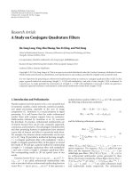
Figure 6 shows the system performance with QPSK
modulation under CM2 channel model. From the figure,
we can see that DFE detection further reduces the effect of
noise enhancement and improves the system performance
compared with linear detectors. The proposed iterative
(turbo) receiver scheme performs better than Q-OFDMA
systems with linear and decision feedback detectors. At
BER
= 10
−4
level, the Q-OFDMA systems with 2 iterations
can achieve it at 17 dB SNR, which is about 2 dB lower
than MMSE equalized Q-OFDMA without iteration process,
and Q-OFDMA systems with more iterations get better
performance. Figure 7 shows BER performance for systems
with 64-QAM modulation, under SUI3 channel model.
Subcarriers have very high correlation due to very limited
number of multipath signals. In this case, the influence of
frequency diversity is weakened, while the noise propagation
is highlighted in Q-OFDMA systems. However, we can see
a similar trend, in BER performance of Q-OFDMA systems
with different order of iterations, to that of Figure 6.
5. Conclusions
In this paper, we analyze linear, decision direct and iter-
ative (turbo) detections for Q-OFDMA systems to miti-
gate the noise enhancement effect and improve the BER
performance. Furthermore, a dedicated turbo equalizer in
BER
10
−4
10
−3
10
−2
10
−1
10
0
SNR (dB)
10 12 14 16 18 20 22 24 26 28 30
Q-OFDMA, ZF, no iteration
Q-OFDMA, MMSE, no iteration
Q-OFDMA, MMSE, 2 iterations
Q-OFDMA, MMSE, 5 iterations
Figure 7: BER performance comparison between Q-OFDMA
systems with different receivers in Wimax channel model, with 64-
QAM modulation.
conjunction with channel estimation for Q-OFDMA systems
is proposed and evaluated. We can judiciously choose
estimation, equalization, and decoding algorithms according
to the performance/complexity tradeoff. From simulations
on wireless dispersive channels, we have shown that Q-
OFDMA with FD-FDE achieves improved performance.
Since both the signal processing and the filter design are
performed entirely in the frequency domain, the complexity
of FD-FDE Q-OFDMA is similar to that of the linearly
equalized Q-OFDMA systems. Moreover, by reducing the
interference and noise enhancement effect, and increasing
the reliability of the detected data, the iterative receiver for
joint estimation, equalization, and decoding significantly
improves the performance of the Q-OFDMA system, with
the similar complexity to the linearly equalized OFDMA/SC-
FDMA systems.
Acknowledgments
NICTA is funded by the Australian Government as repre-
sented by the Department of Broadband, Communications
and the Digital Economy, and the Australian Research
Council through the ICT Centre of Excellence program.
References
[1] A. Czylwik, “Comparison between adaptive OFDM and single
carrier modulation with frequency domain equalization,” in
Proceedings of the 47th IEEE Vehicular Technology Conference
(VTC ’97), vol. 2, pp. 865–869, Phoenix, Ariz, USA, May 1997.
[2] D. Falconer, S. L. Ariyavisitakul, A. Benyamin-Seeyar, and
B. Eidson, “Frequency domain equalization for single-carrier
EURASIP Journal on Wireless Communications and Networking 9
broadband wireless systems,” IEEE Communications Magazine,
vol. 40, no. 4, pp. 58–66, 2002.
[3] H. G. Myung, J. Lim, and D. J. Goodman, “Single carrier
FDMA for uplink wireless transmission,” IEEE Vehicular
Technology Magazine, vol. 1, no. 3, pp. 30–38, 2006.
[4] J. Zhang, L. Luo, and Z. Shi, “Quadrature OFDMA systems,”
in Proceedings of the 50th Annual IEEE Global Telecom-
munications Conference (GLOBECOM ’07), pp. 3734–3739,
Washington, DC, USA, November 2007.
[5]J.G.Proakis,Digital Communications, McGraw-Hill, New
York, NY, USA, 4th edition, 2001.
[6] G. K. Kaleh, “Channel equalization for block transmission
systems,” IEEE Journal on Selected Areas in Communications,
vol. 13, no. 1, pp. 110–121, 1995.
[7] F. Pancaldi and G. M. Vitetta, “Block channel equalization in
the frequency domain,” IEEE Transactions on Communications,
vol. 53, no. 3, pp. 463–471, 2005.
[8] N. Benvenuto and S. Tomasin, “On the comparison between
OFDM and single carrier modulation with a DFE using a
frequency-domain feedforward filter,” IEEE Transactions on
Communications, vol. 50, no. 6, pp. 947–955, 2002.
[9] N. Benvenuto and S. Tomasin, “Iterative design and detection
of a DFE in the frequency domain,” IEEE Transactions on
Communications, vol. 53, no. 11, pp. 1867–1875, 2005.
[10] C.Douillard,M.J
´
ez
´
equel, C. Berrou, A. Picart, P. Didier, and
A. Glavieux, “Iterative correction of intersymbol interference:
turbo-equalization,” European Transactions on Telecommuni-
cations, vol. 6, no. 5, pp. 507–511, 1995.
[11] X. Wang and H. V. Poor, “Iterative (turbo) soft interference
cancellation and decoding for coded CDMA,” IEEE Transac-
tions on Communications, vol. 47, no. 7, pp. 1046–1061, 1999.
[12] M. T
¨
uchler and J. Hagenauer, “Linear time and frequency
domain turbo equalization,” in Proceedings of the 53rd IEEE
Vehicular Technology Conference (VTC ’01), vol. 2, pp. 1449–
1453, Rhodes, Greece, May 2001.
[13] M. T
¨
uchler, R. Koetter, and A. C. Singer, “Turbo equalization:
principles and new results,” IEEE Transactions on Communica-
tions, vol. 50, no. 5, pp. 754–767, 2002.
[14] L. M. Davis, I. B. Collings, and P. Hoeher, “Joint MAP
equalization and channel estimation for frequency-selective
and frequency-flat fast-fading channels,” IEEE Transactions on
Communications, vol. 49, no. 12, pp. 2106–2114, 2001.
[15] M. Qaisrani and S. Lambotharan, “An iterative (turbo) chan-
nel estimation and symbol detection technique for doubly
selective channels,” in Proceedings of the 65th IEEE Vehicular
Technology Conference ( VTC ’07), pp. 2253–2256, Dublin,
Ireland, April 2007.
[16] T. Zemen, J. Wehinger, C. Mecklenbr
¨
auker, and R. M
¨
uller,
“Iterative detection and channel estimation for MC-CDMA,”
in Proceedings of IEEE International Conference on Communi-
cations (ICC ’03), vol. 5, pp. 3462–3466, Anchorage, Alaska,
USA, May 2003.
[17] L. Luo, J. Zhang, and Z. Shi, “BER analysis for asymmetric
OFDM systems,” in Proceedings of IEEE Global Te lecommuni-
cations Conference (GLOBECOM ’08), pp. 1–6, New Orleans,
La, USA, November-December 2008.
[18] Z. Wang and G. B. Giannakis, “Complex-field coding for
OFDM over fading wireless channels,” IEEE Transactions on
Information Theory
, vol. 49, no. 3, pp. 707–720, 2003.
[19] A. Stamoulis, G. B. Giannakis, and A. Scaglione, “Block FIR
decision-feedback equalizers for filterbank precoded trans-
missions with blind channel estimation capabilities,” IEEE
Transactions on Communications, vol. 49, no. 1, pp. 69–83,
2001.
[20] H. Omori, T. Asai, and T. Matsumoto, “A matched filter
approximation for SC/MMSE iterative equalizers,” IEEE Com-
munications Letters, vol. 5, no. 7, pp. 310–312, 2001.
[21] G. Bauch and V. Franz, “A comparison of soft-in/soft-
out algorithms for “turbo-detection”,” in Proceedings of the
International Conference on Telecommunications (ICT ’98),pp.
259–263, Porto Carras, Greece, June 1998.