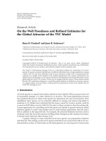
Báo cáo hóa học: "Research Article On the Information Rate of Single-Carrier FDMA Using Linear Frequency Domain Equalization and Its Application for 3GPP-LTE Uplink" doc
Bạn đang xem bản rút gọn của tài liệu. Xem và tải ngay bản đầy đủ của tài liệu tại đây (823.92 KB, 11 trang )
Hindawi Publishing Corporation
EURASIP Journal on Wireless Communications and Networking
Volume 2009, Article ID 957159, 11 pages
doi:10.1155/2009/957159
Research Article
On the Information Rate of Single-Carrier FDMA Using
Linear Frequency Domain Equalization and Its Application for
3GPP-LTE Uplink
Hanguang Wu,
1
Thomas Haustein (EURASIP Member),
2
and Peter Adam Hoeher
3
1
COO RTP PT Radio System Technology, Nokia Siemens Networks, St. Martin Street 76, 81617 Munich, Germany
2
Fraunhofer Institute for Telecommunications, Heinrich Hertz Institute, Einsteinufer 37, 10587 Berlin, Germany
3
Faculty of Engineering, University of Kiel, Kaiserstraße 2, 24143 Kiel, Germany
Correspondence should be addressed to Hanguang Wu,
Received 31 January 2009; Revised 25 May 2009; Accepted 19 July 2009
Recommended by Bruno Clerckx
This paper compares the information rate achieved by SC-FDMA (single-carrier frequency-division multiple access) and OFDMA
(orthogonal frequency-division multiple access), where a linear frequency-domain equalizer is assumed to combat frequency
selective channels in both systems. Both the single user case and the multiple user case are considered. We prove analytically
that there exists a rate loss in SC-FDMA compared to OFDMA if decoding is performed independently among the received data
blocks for frequency selective channels. We also provide a geometrical interpretation of the achievable information rate in SC-
FDMA systems and point out explicitly the relation to the well-known waterfilling procedure in OFDMA systems. The geometrical
interpretation gives an insight into the cause of the rate loss and its impact on the achievable rate performance. Furthermore,
motivated by this interpretation we point out and show that such a loss can be mitigated by exploiting multiuser diversity and
spatial diversity in multi-user systems with multiple receive antennas. In particular, the performance is evaluated in 3GPP-LTE
uplink scenarios.
Copyright © 2009 Hanguang Wu et al. This is an open access article distributed under the Creative Commons Attribution License,
which permits unrestricted use, distribution, and reproduction in any medium, provided the original work is properly cited.
1. Introduction
In high data rate wideband wireless communication sys-
tems, OFDM (orthogonal frequency-division multiplexing)
and SC-FDE (single-carrier system with frequency domain
equalization), are recognized as two popular techniques
to combat the frequency selectivity of the channel. Both
techniques use block transmission and employ a cyclic
prefix at the transmitter which ensures orthogonality and
enables efficient implementation of the system using the fast
Fourier transform (FFT) and one tap scalar equalization per
subcarrier at the receiver. There has been a long discussion
on a comparison between OFDM and SC-FDE concerning
different aspects [1–3]. In order to accommodate multiple
users in the system, OFDM can be straightforward extended
to a multiaccess scheme called OFDMA, where each user is
assigned a different set of subcarriers. However, an extension
to an SC-FDE based multiaccess scheme is not obvious and it
has been developed only recently, called single-carrier FDMA
(SC-FDMA) [4]. (A single-carrier waveform can only be
obtained for some specific sub-carrier mapping constraints.
In this paper we do not restrict ourself to these constraints
but refer SC-FDMA to as DFT-precoded OFDMA with
arbitrary sub-carrier mapping.) SC-FDMA can be viewed
as a special OFDMA system with the user’s signal pre-
encoded by discrete Fourier transform (DFT), hence also
known as DFT-precoded OFDMA or DFT-spread OFDMA.
One prominent advantage of SC-FDMA over OFDMA is the
lower PAPR (peak-to-average power ratio) of the transmit
waveform for low-order modulations like QPSK and BPSK,
which benefits the mobile users in terms of power efficiency
[5]. Due to this advantage, recently SC-FDMA has been
agreed on to be used for 3GPP LTE uplink transmission
[6]. (LTE (Long Term Evolution) is the evolution of the
3G mobile network standard UMTS (Universal Mobile
Telecommunications System) defined by the 3rd Generation
2 EURASIP Journal on Wireless Communications and Networking
Channel
Add CP
Remove CP
Sub-carrier mapping
Sub-carrier
demapping
M
M
H
d
x
y
r
H
v
Q point
FFT
Q point
IFFT
N point
DFT
N point
IDFT
EQ
OFDMASC-FDMA
x
d
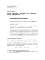
Figure 1: Block diagram of SC-FDMA systems and its relation to OFDMA systems.
Partnership Project (3GPP).) In order to obtain a PAPR
comparable to the conventional single carrier waveform in
the SC-FDMA transmitter, sub-carriers assigned to a specific
user should be adjacent to each other [7] or equidistantly
distributed over the entire bandwidth [8], where the former
is usually referred to as localized mapping and the latter
distributed mapping.
This paper investigates the achievable information rate
using SC-FDMA in the uplink. We present a framework for
analytical comparison between the achievable rate in SC-
FDMA and that in OFDMA. In particular, we compare the
rate based on a widely used transmission structure in both
systems, where equal power allocation (meaning a flat power
spectral density mask) is used for the transmitted signal
of each user, and linear frequency domain equalization is
employed at the receiver.
The fact that OFDMA decomposes the frequency-
selective channel into parallel AWGN sub-channels suggests a
separate coding for each sub-channel without losing channel
capacity, where independent near-capacity-achieving AWGN
codes can be used for each sub-channel and accordingly the
received signal is decoded independently among the sub-
channels. This communication structure is of high interest
both in communication theory and in practice, since near-
capacity-achieving codes (e.g., LDPC and Turbo codes) have
been well studied for the AWGN channel. We show that
although SC-FDMA can be viewed as a collection of virtual
Gaussian sub-channels, these sub-channels are correlated;
hence separate coding and decoding for each of them is not
sufficient to achieve channel capacity. We further investigate
the achievable rate in SC-FDMA if a separate capacity-
achieving AWGN code for each sub-channel is used subject
to equal power allocation of the transmitted signal. The
special case that all the sub-carriers are exclusively utilized
by a single user, that is, SC-FDE, is investigated in [3],
and it is shown that the SC-FDE rate is always lower than
the OFDM rate in frequency selective channels. However,
an insight into the cause of the rate loss and its impact
on the performance was not given. Such an insight is of
interest and importance to design appropriate transmission
strategies in SC-FDMA systems, where a number of sub-
carriers and multi-users or possibly multiple antennas are
involved. In this paper, based on the property of the circular
matrix we derive a framework of rate analysis for SC-
FDMA and OFDMA, which is a generalization of the result
in [3], and it allows for the calculation of the achievable
rate using arbitrary sub-carrier assignment methods in both
the single user system and the multi-user system subject
to individual power constraints of the users. We analyze
the cause of the rate loss and its impact on the achievable
rate as well as provide the geometrical interpretation of
the achievable rate in SC-FDMA. Moreover, we reveal an
interesting relation between the geometrical interpretation
and the well-known waterfilling procedure in OFDMA
systems. More importantly, motivated by this geometrical
interpretation we show that such a loss can be mitigated by
exploiting multi-user diversity and spatial diversity in the
multi-user system with multiple receive antennas, which is
usually available in mobile systems nowadays.
The paper is organized as follows. In Section 2 we
introduce the system model and the information rate for
OFDMA and SC-FDMA. In Section 3 we derive the SC-
FDMA rate result and provide its geometrical interpretation
assuming equal power allocation without joint decoding.
Then we extend and discuss the SC-FDMA rate result for the
multi-user case and for multi-antenna systems in Section 4.
Simulation results are given in Section 5, and conclusions are
drawn in Section 6.
2. System Model and Information Rate
Consider the SC-FDMA uplink transmission scheme
depicted in Figure 1.Theonlydifference from OFDMA is
EURASIP Journal on Wireless Communications and Networking 3
the addition of the N point DFT at the transmitter and
the N point IDFT at the receiver. The transmitted signal
block d
= [d
0
, , d
N−1
]
T
of size N spreads onto the N
sub-carriers selected by the sub-carrier mapping method. In
other words, the transmitted signal vector is pre-encoded by
DFT before going to the OFDMA modulator. For OFDMA
transmission, a specific set of sub-carriers is assigned to
the user through the sub-carrier mapping stage. Then
multi-carrier modulation is performed via a Q point IFFT
(Q>N), and a cyclic prefix (CP) longer than the maximum
channel delay is inserted to avoid interblock interference.
The frequency selective channel can be represented by a tap
delay line model with the tap vector h
= [h
0
, h
1
, , h
L
]
T
and
the additive white Gaussian noise (AWGN) v
∼ N (0,N
0
).
At the receiver, the CP is removed and a Q point FFT
is performed. A demapping procedure consisting of the
spectral mask of the desired user is then applied, followed
by zero forcing equalization which involves a scalar channel
inversion per sub-carrier. For SC-FDMA, the equalized
signal is further transformed to the time domain using an N
point IDFT where decoding and detection take place.
In the following, we first briefly review the achievable
sum rate in the OFDMA system and then show the sum rate
relationship between OFDMA and SC-FDMA. We assume in
the uplink that the users’ channels are perfectly measured
by the base station (BS), where the resource allocation
algorithm takes place and its decision is then sent to the users
via a signalling channel in the downlink. For simplicity, we
start with the single-user single-input single-output system
and then extend it to the multi-user case with multiple
antennas at the BS. For convenience, the following notations
are employed throughout the paper. F
N
is the N ×N Fourier
matrix with the (n, k)th entry [F
N
]
n,k
= (1/
√
N)e
−j2πnk/N
,
and F
H
N
denotes the inverse Fourier matrix. Further on, the
assignment of data symbols x
n
to specific sub-carriers is
described by the Q
× N sub-carrier mapping matrix M with
the entry
m
q,n
=
⎧
⎨
⎩
1, if the nth data is assigned to the qth sub-carrier
0, otherwise,
(1)
0
≤ q ≤ Q −1, 0 ≤ n ≤ N −1.
2.1. OFDMA Rate. After CP removal at the receiver, the
receivedblockcanbewrittenas
y
= HF
H
Q
Mx + v,(2)
where x
= [x
0
, , x
N−1
] is the transmitted block of
the OFDMA system, and H is a Q
× Q circulant matrix
with the first column h
= [h
0
, , h
L−1
,0, ,0]
T
.The
following discussion makes use of the important properties
of circulant matrices given in the appendices (Facts 1 and 2).
Performing multi-carrier demodulation using FFT and sub-
carrier demapping using M
H
, we obtain the received block
r
= M
H
F
Q
y = M
H
F
Q
HF
H
Q
Mx + M
H
F
Q
v (3)
= M
H
DMx + M
H
F
Q
v (4)
= M
H
MΛx + M
H
F
Q
v (5)
= Λx + η,(6)
where Fact 1 (see Appendix A)isusedfromstep(3)to(4)
and D
= F
Q
HF
H
Q
= diag{
h} with the diagonal entries being
the frequency response of the channel. The step (4)to(5)
follows from the equality
DM
= MΛ,(7)
where Λ
= diag{
h
0
,
h
1
, ,
h
N−1
} is an N × N diagonal
matrix with its diagonal entries being the channel frequency
response at the selected sub-carriers of the user. This
relationship can be readily verified since M has only a single
nonzero unity entry per column, and this structure of M also
leads to
M
H
M = I
N
,(8)
with which we arrive at step (6). The N
×1vectorη = M
H
F
Q
v
is a linear transformation of v, and hence it remains Gaussian
whose covariance matrix is given by
E
ηη
H
= E
M
H
F
Q
vv
H
F
H
Q
M
=
M
H
F
Q
E{vv
H
}F
H
Q
N
0
I
Q
M
(9)
= N
0
M
H
I
Q
M (10)
= N
0
M
H
MI
N
(11)
= N
0
I
N
, (12)
where the step (9)to(10)followsfromFact2 (see
Appendix A), (10)to(11) follows from (7) since I
Q
is
also a diagonal matrix, and the step (11)to(12) results
from (8). Therefore, η is a vector consisting of uncorrelated
Gaussian noise samples. The frequency domain ZF equalizer
is given by the inverse of the diagonal matrix Λ
−1
which
essentially preserves the mutual information provided that Λ
is invertible. Here we assume that Λ is always invertible since
the BS can avoid assigning sub-carriers with zero channel
frequency response to the user. Due to the diagonal structure
of Λ and independent noise samples of η (uncorrelated
Gaussian samples are also independent), (6)canbeviewed
as the transmit signal components or the data symbols on
the assigned sub-carriers propagating through independent
Gaussian sub-channels with different gains. This structure
suggests that coding can be done independently for each sub-
channel to asymptotically achieve the channel capacity. The
only loss is due to the cyclic prefix overhead relative to the
transmit signal block length. The achievable sum rate of an
4 EURASIP Journal on Wireless Communications and Networking
ZF equalizer
OFDM channel
N point
IDFT
N point
DFT
h
0
h
N−1
x
0
d
0
x
N−1
d
N−1
η
0
η
N
−
1
h
0
1/
h
N
−
1
1/
x
0
x
N
−
1
d
0
d
N−1
. . .
. . .
. . .
. . .
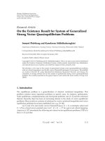
Figure 2: Equivalent block diagram of SC-FDMA systems.
OFDMA system can be calculated as the sum of the rates of
the assigned sub-carriers, which is given by
C
OFDMA
=
N−1
n=0
log
2
⎛
⎜
⎝
1+
P
n
h
n
2
N
0
⎞
⎟
⎠
, (13)
where P
n
is the power allocated to the nth sub-carrier.
Note that the employment of a zero forcing (ZF) equalizer
performing channel inversion for each sub-carrier preserves
the capacity since the resulting signal-to-noise ratio (SNR)
for each sub-carrier remains unchanged. To maximize the
OFDMA rate subject to the total transmit power constraint
P
total
, the assignment of the transmit power to the n indepen-
dent Gaussian sub-channels should follow the waterfilling
principle, and so the optimal power P
n
of the nth sub-carrier
is given by
P
n
= max
⎛
⎜
⎝
0, λ −
N
0
h
n
2
⎞
⎟
⎠
, (14)
where the positive constant λ must be chosen in order to
fulfill the total transmit power constraint
P
total
= tr
xx
H
=
N−1
n=0
max
⎛
⎜
⎝
0, λ −
N
0
h
n
2
⎞
⎟
⎠
, (15)
where tr
{·} stands for the trace of the argument. It should
be noted that the waterfilling procedure implicitly selects
the optimal sub-carriers out of the available sub-carriers
in the system and assigns optimal transmit power to each
of them. Therefore, it is possible that some sub-carriers
are not used. In our model, the waterfilling procedure
amounts to mapping x to the desired sub-carriers and at the
same time constructing x having diagonal covariance matrix
R
x
= diag{P
0
, P
1
, , P
N−1
}with entries equal to the optimal
power allocated to the desired sub-carriers.
2.2. SC-FDMA Rate. OFDMA converts the frequency selec-
tive channels into independent AWGN channels with dif-
ferent gains. Therefore, a block diagram of SC-FDMA can
be equivalently regarded as applying DFT precoding for
parallel AWGN channels and performing IDFT decoding
after equalization as illustrated in Figure 2. The output of the
IDFT can be derived as
d = F
H
N
Λ
−1
r = F
H
N
Λ
−1
Λx + F
H
N
Λ
−1
η
= F
H
N
Λ
−1
ΛF
N
d + F
H
N
Λ
−1
η
= d + F
H
N
Λ
−1
η
= d + η,
(16)
where we denote
η = F
H
N
Λ
−1
η by the residual noise
vector after ZF equalizer and IDFT. With (16) the transmit
data components in SC-FDMA system can be viewed as
propagating through virtual sub-channels distorted by the
amount of noise given by
η. Note that η is a Gaussian vector
due to the linear transformation but it is entries are generally
correlated which we show in the following:
R
η
= E
ηη
H
=
E
F
H
N
Λ
−1
ηη
H
Λ
−H
F
N
=
F
H
N
Λ
−1
E
ηη
H
Λ
−H
F
N
= N
0
F
H
N
Λ
−1
Λ
−H
F
N
(17)
= N
0
F
H
N
|Λ|
−2
diagonal
F
N
circulant
, (18)
where
|·|is applied to Λ elementwise, and the step from
(17)to(18) follows from the fact that Λ is a diagonal
matrix. The matrix
|Λ|
−2
is hence also diagonal with the
diagonal entries being the reciprocal of channel power gains
of the assigned sub-carriers of the user, which are usually not
equal in frequency selective channels. Hence R
η
is a circulant
matrix according to Fact 2 (see Appendix A)withnonzero
values on the off diagonal entries. Therefore, the residual
noise on the virtual sub-channels is correlated and hence SC-
FDMA does not have the same parallel AWGN sub-channel
representation as OFDMA. However, note that the DFT at
the SC-FDMA transmitter does not change the total transmit
EURASIP Journal on Wireless Communications and Networking 5
power due to the property of the Fourier matrix F
H
F = I, that
is,
P
x
= x
H
x = d
H
F
H
Fd = d
H
d = P
d
. (19)
The property of power conservation of the DFT precoder at
the transmitter and invertibility of IDFT at the receiver leads
to the conclusion that the mutual information is preserved.
Hence, the mutual information between the transmit vector
and post-detection vector I(d,
d)isequaltothatofOFDMA
I(x,
x). In other words, for any sub-carrier mapping and
power allocation methods in OFDMA system, there exists
a corresponding configuration in SC-FDMA which achieves
the same rate as OFDMA. For example, suppose, for a given
time invariant frequency selective channel, that R
x
is the
optimal covariance matrix given by the waterfilling solution
in an OFDMA system. To obtain the same rate in an SC-
FDMA system, the covariance matrix of the transmitted
signal R
d
can be designed as
R
d
= E
dd
H
=
E
F
H
xx
H
F
=
F
H
E
xx
H
diag
{
p
}
F
circulant
{
p
}
, (20)
where in the last step we use Fact 2 (see Appendix A).
Hence, R
d
is a circulant matrix with the first column
p = (1/
√
N)F
H
p. Since both the covariance matrix of the
transmitted signal and residual noise exhibit a circulant
structure in an SC-FDMA system, correlation exists in
both the transmitted symbols before DFT and the received
symbols after IDFT. Such correlation complicates the code
design problem in order to achieve the same rate as in
OFDMA. This paper makes no attempt to design a proper
coding scheme for SC-FDMA but we mention that SC-
FDMA is not inferior to OFDMA regarding the achievable
information rate from an information theoretical point of
view. Instead, it can achieve the same rate as OFDMA if
proper coding is employed. Note that the above statement
implies using the same sub-carriers to convey information
in both systems. Therefore, SC-FDMA and OFDMA are the
same regarding the rate if they both use the same sub-carrier
and the same corresponding power for each sub-carrier
to convey information. However, in SC-FDMA coding and
decoding should be applied across the transmitted and
received signal components, respectively.
3. SC-FDMA Rate Using Equal Power Allocation
without Joint Decoding
The waterfilling procedure discussed above is computation-
ally complex which requires iterative sub-carrier and power
allocation in the system. An efficient sub-optimal approach
with reduced complexity is to use equal power allocation
across a properly chosen subset of sub-carriers [9], which
is shown to have very close performance to the waterfilling
solution. In other words, this approach assumes E
{xx
H
}=
(P
total
/N)I
Δ
= P
e
I and designs a proper sub-carrier mapping
matrix to approximate the waterfilling solution, where the
number of used sub-channels N is also a design parameter.
This approach can also be applied to an SC-FDMA system to
approximate the waterfilling solution since DFT precoding
and decoding are information lossless according to our
discussion in Section 2. Note that DFT precoding does
not change the equal power allocation property of the
transmitted signal according to Fact 2 (see Appendix A), that
is, E
{dd
H
}=E{xx
H
}=P
e
I (P
x
= P
d
= P
total
). Therefore, to
obtain the same rate as in OFDMA, coding does not need to
be applied across transmitted signal components, and only
correlation among the received signal components needs to
be taken into account for decoding.
3.1. SC-FDMA Rate without Joint Decoding. We are inter-
ested to see what the achievable rate in SC-FDMA is if a
capacity-achieving AWGN code is used for each transmitted
component, which is decoded independently at the receiver.
Under the above given condition, the achievable rate in SC-
FDMA is the sum of the rate of each virtual subchannel for
which we need to calculate the post-detection SNR, that is,
the post-detection SNR of the nth virtual subchannel can be
expressed as
γ
SC-FDMA,n
=
P
e
E
ηη
H
n,n
=
P
e
N
0
N−1
n=0
1/
h
n
2
/N
=
NP
e
N
0
N−1
n
=0
1/
h
n
2
=
HM
h
n
·
P
e
N
0
(21)
= γ. (22)
In step (21)wedenoteHM(
|
h
n
|
2
) = N/
N−1
n
=0
(1/|
h
n
|
2
)
which is the harmonic mean of
|
h
n
|
2
,(n = 0, , N − 1) by
definition. In the last step we let γ
= (HM(|
h
n
|
2
) · P
e
)/N
0
since the post-detection SNR is equal for all the virtual
subchannels. Using Shannon’s formula the achievable rate in
SC-FDMA can be obtained as
C
EP, Independent
SC-FDMA
= N log
2
1+γ
=
N log
2
⎛
⎜
⎜
⎝
1+
HM
h
n
2
·
P
e
N
0
⎞
⎟
⎟
⎠
,
(23)
which is a function of the harmonic mean of the power
gains at the assigned sub-carriers. Note that the result in
[3]isaspecialcaseof(23) where all the available sub-
carriers in the system are used by the user. It is perceivable
that C
EP,Independent
SC-FDMA
≤ C
EP
OFDM
because noise correlation
between the received components is not exploited to recover
6 EURASIP Journal on Wireless Communications and Networking
the signal. In the following, we will prove this inequality
analytically. In order to prove
N log
2
⎛
⎜
⎜
⎝
1+
HM
h
n
2
·
P
e
N
0
⎞
⎟
⎟
⎠
≤
N−1
n=0
log
2
⎛
⎜
⎝
1+
h
n
2
P
e
N
0
⎞
⎟
⎠
,
(24)
it is equivalent to prove
⎛
⎜
⎜
⎝
1+
HM
h
n
2
·
P
e
N
0
⎞
⎟
⎟
⎠
N
≤
N−1
n=0
⎛
⎜
⎝
1+
h
n
2
P
e
N
0
⎞
⎟
⎠
, (25)
since log
2
(·) is a monotonically increasing function. Because
the term (1 + (
|
h
n
|
2
P
e
)/N
0
) is positive and the geometric
mean of positive values is not less than the harmonic mean,
we have
⎛
⎜
⎝
N−1
n=0
⎛
⎜
⎝
1+
h
n
2
P
e
N
0
⎞
⎟
⎠
⎞
⎟
⎠
1/N
≥
N
N−1
n=0
1/
1+
h
n
2
P
e
/N
0
.
(26)
The Hoehn-Niven theorem [10] states the following: Let
HM(
·) be the harmonic mean and let a
1
, a
2
, , a
m
, x be the
positive numbers, where the a
i
’s are not all equal, then
HM
(
x + a
1
, x + a
2
, , x + a
m
)
>x+ HM
(
a
1
, a
2
, , a
m
)
(27)
holds. If we let a
n
= (|
h
n
|
2
P
e
)/N
0
,foralln and x = 1, by
applying (27)wehave
N
N−1
n
=0
1/
1+
h
n
2
P
e
/N
0
> 1+HM
⎛
⎜
⎝
h
n
2
P
e
N
0
⎞
⎟
⎠
=
1+HM
h
n
2
P
e
N
0
,
(28)
where the last step follows from the fact that P
e
/N
0
is a
constant value so that it can be factored out of the HM(
·)
operation. Therefore, by applying the transitive property of
inequality to (26)and(28) it follows that
⎛
⎜
⎝
N−1
n=0
⎛
⎜
⎝
1+
h
n
2
P
e
N
0
⎞
⎟
⎠
⎞
⎟
⎠
1/N
> 1+HM
h
n
2
P
e
N
0
, (29)
and taking the Nth power on both sides of (29), we have
⎛
⎜
⎜
⎝
1+
HM
h
n
2
·
P
e
N
0
⎞
⎟
⎟
⎠
N
<
N−1
n=0
⎛
⎜
⎝
1+
h
n
2
P
e
N
0
⎞
⎟
⎠
. (30)
By definition, it is easy to prove that if all the
|
h
n
|
2
, n =
0, , N − 1areequal,HM(|
h
n
|
2
) =|
h
n
|
2
holds and thus
⎛
⎜
⎜
⎝
1+
HM
h
n
2
·
P
e
N
0
⎞
⎟
⎟
⎠
N
=
N−1
n=0
⎛
⎜
⎝
1+
h
n
2
P
e
N
0
⎞
⎟
⎠
(31)
holds, which corresponds to the case of frequency flat fading.
Therefore, (24) holds in general.
The harmonic mean is sensitive to a single small value.
HM(
|
h
n
|
2
) tends to be small if one of the values |
h
n
|
2
is small. Therefore, the achievable sum rate in SC-FDMA
depending on the harmonic mean of the power gain of
the assigned sub-carriers would be sensitive to one single
deep fade whose sub-carrier power gain is small. To give an
intuitive impression how sensitive it is, we make use of the
geometrical interpretation of the harmonic mean by Pappus
of Alexandria [11] which is provided in Appendix B.
3.2. Relation to OFDMA. In the following, we will show
that the achievable sum rate of SC-FDMA using equal
power allocation without joint decoding is equivalent to that
achieved by nonprecoded OFDMA system with equal gain
power (EGP) allocation among the assigned sub-carriers.
This conclusion will lead to our geometrical interpretation
of the SC-FDMA system.
In an OFDMA system, the EGP allocation strategy pre-
equalizes the transmitted signal so that all gains of the
assigned sub-carriers are equal, that is,
P
n
h
n
2
N
0
= constant, ∀n,
subject to
n
P
n
= P
total
,
(32)
which requires the power allocated to the nth assigned sub-
carrier P
eg,n
to be
P
eg,n
=
P
total
h
n
2
N−1
n=0
1/
h
n
2
. (33)
Upon insertion of (33) into (13), the achievable sum rate
using EGP can be calculated as
C
EGP
OFDMA
= N log
2
⎛
⎜
⎜
⎝
1+
P
total
N−1
n
=0
1/
h
n
2
⎞
⎟
⎟
⎠
=
N log
2
⎛
⎜
⎜
⎝
1+
HM
h
n
2
·
P
e
N
0
⎞
⎟
⎟
⎠
,
(34)
EURASIP Journal on Wireless Communications and Networking 7
P
0
= 0
P
1
P
2
P
3
Index of the assigned sub-carriers
Water level
Waterfilling power allocation
N
0
|
h
n
|
2
(a)
Equal gain power allocation
P
2
= 0
log
10
P
0
log
10
P
1
log
10
P
3
Index of the assigned sub-carriers
Water level
log
10
|
h
n
|
2
N
0
(b)
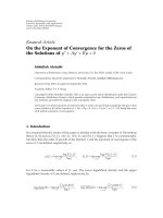
Figure 3: Comparison of geometrical interpretation between the waterfilling power allocation (a) and equal gain power allocation (b).
which is equal to C
EP, Independent
SC-FDMA
in (23), provided that both
the SC-FDMA and OFDMA systems use the same assigned
sub-carriers. This result leads to the conclusion that ZF
equalized SC-FDMA with equal power allocation can be
viewed as a nonprecoded OFDMA system performing EGP
allocation among the assigned sub-carriers. It is worthy to
point out that we find that EGP allocation shares a similar
geometrical interpretation with waterfilling. This statement
can be proven by applying logarithmic operation at both
sides of the objective function of (32), which becomes
log
10
P
n
+log
10
⎛
⎜
⎝
h
n
2
N
0
⎞
⎟
⎠
=
log
10
(
constant
)
= constant, ∀n
subject to
n
P
n
= P
total
,
(35)
where the objective function can be interpreted as shown in
Figure 3(b): we can imagine that the quantity log
10
(|
h
n
|
2
/N
0
)
is the bottom of a container and a fixed amount of water
(power), P
total
, is poured into the container. The water will
then distribute inside the container to maintain a water
level, denoted as constant in (35). Then the distance between
the container bottom and the water level, that is, log
10
P
n
,
represents the power allocated to the nth assigned sub-
carrier. Note that the waterfilling interpretation of EGP
differs from the conventional waterfilling procedure of (14)
in that firstly the container bottom is the inverse of that of the
conventional waterfilling, and secondly the container bottom
and the resulting power allocated to the individual sub-
carrier should be measured in decibel. With the waterfilling
interpretation of EGP it is possible to visualize how power
is distributed among selected sub-carriers for ZF equalized
SC-FDMA and also explain why putting power into weak
sub-channels wastes so much capacity. Due to the inverse
property of the container bottom, EGP allocates a larger
portion of power to weaker sub-carriers and a smaller
portion of power to stronger sub-carriers, which is opposite
to the conventional waterfilling solution. Therefore, in order
to achieve a higher data rate in SC-FDMA, it is important not
to include weaker sub-carriers for communication because
larger amount of power would be “wasted” in those sub-
carriers. This observation suggests using strong sub-carriers
for communication where an optimal sub-carrier allocation
method, that is, optimal EGP allocation, is proposed in
[12]. In frequency selective channels, such strong sub-
carriers are usually not to be found adjacent to each
other or equidistantly distributed over the entire bandwidth.
Therefore, the sub-carrier mapping constraints to maintain
the nice low PAPR for SC-FDMA has to be compromised
if the optimal EGP allocation is applied. Within the scope
of the work, we do not investigate such trade-off between
the PAPR reduction and rate maximization. Instead, we will
discuss in the following section that it is possible to obtain
comparable rate performance as OFDMA and low PAPR
as the single carrier waveform at the same time if multiple
antennas are available at the BS.
4. Extension to Multiuser Case and
Multiantenna Systems
The information rate analysis in Sections 2 and 3 assumes
only one user in the system. However, the principle also
holds for the multi-user case where each user’s signal will
be first individually precoded by DFT and then mapped to
adifferent set of sub-carriers. It is known that in the multi-
user OFDMA system, the maximum sum rate of all the users
can be obtained by the multi-user waterfilling solution [13]
where each user subject to an individual power constraint
is assigned a different set of sub-carriers associated with a
given power. Therefore, the information rate achieved in
the system can be calculated as a sum of rate of each user,
which can again be calculated similarly as in the single-
user system. As a result, a multi-user SC-FDMA system can
achieve the same rate as a multi-user OFDMA system since
DFT and IDFT essentially preserve the mutual information
of each user if the same resource allocation is assumed. If
equal power allocation of the transmitted signal without
joint decoding is assumed for each user, the system sum
8 EURASIP Journal on Wireless Communications and Networking
rate C
EP,Independent
SC-FDMA,MU
of U users can be straightforward extended
from (23), that is,
C
EP, Independent
SC-FDMA,MU
=
U
u=1
N
u
log
2
1+γ
u
=
U
u=1
N
u
log
2
⎛
⎜
⎜
⎝
1+
HM
h
n,u
2
·
P
n,u
N
0
⎞
⎟
⎟
⎠
,
(36)
where N
u
is the length of the transmitted signal block of the
uth user whose post-detection SNR is denoted as γ
u
, P
n,u
is
the power of the nth transmitted symbol of the uth user, and
h
n,u
is the channel frequency response at the nth assigned
subcarrier of the uth user. The geometrical interpretation
of the achievable sum rate in the multiuser SC-FDMA
system can be straightforward interpreted as performing
multiuser EGP allocation in the system, where each user,
subject to a given transmit power constraint, performs EGP
allocation in the assigned set of subcarriers. It can be proven
that C
EP, Independent
SC-FDMA,MU
≤ C
EP
OFDMA,MU
=
U
u
=1
N
u
−1
n
=0
log
2
(1 +
(
|
h
n,u
|·P
n,u
)/N
0
) by summing up the rate of all the users,
each of which obeys (24), where the equality occurs when
the channel frequency response at the assigned sub-carriers
of each user is equal; that is, each user experiences flat
fading among the assigned subcarriers for communication
but the channel power gains can be different for different
users. Note that the optimal multi-user waterfilling solution
tends to exploit multi-user diversity and schedule at any
time and any subcarrier of the user with the highest sub-
carrier power gain-to-noise ratio to transmit to the BS.
Consequently, from the system point of view, only the
relatively strong sub-carriers, possibly from different users,
are selected and the relative weak ones are avoided. In other
words, each user is only assigned a set of relative strong sub-
carriers. It will be a good choice if the above sub-carrier
allocation scheme is applied for each user in SC-FDMA
systems, because it is essentially equivalent to performing
EGP among the relative strong sub-carriers for each user.
As the number of users increases, the weak sub-carriers can
be more effectively avoided due to the multi-user diversity.
As a result, the effective channel for each user becomes less
frequency selective, and the rate loss in SC-FDMA compared
to OFDMA becomes smaller. The same effect happens if the
BS is equipped with multiple antennas to exploit the spatial
diversity to harden the channels. For SC-FDMA with the
localized mapping constraint or the equidistantly distributed
mapping constraint, multi-user diversity may help to reduce
the rate loss with respect to an OFDMA system but with
less degrees of freedom because multi-user diversity cannot
guarantee that good sub-carriers assigned to each user are
adjacent to each other or equidistantly distributed in the
entire bandwidth. In this case, spatial diversity is much
more important because it can always reduce frequency
selectivity of each user’s channel by using, for example, a
maximum ratio combiner (MRC) at the receiver. As a result,
the user specific resource allocation has less influence on
Table 1: Parameter assumptions for simulation
Parameters Assumption
Carrier frequency 2.0 GHz
Transmission bandwidth
1.25 MHz, 2.5 MHz, 5 MHz,
10 MHz, 15 MHz and 20 MHz
Subcarrier spacing 15 KHz
Number of subcarriers
in the system
75, 150, 300, 600, 900 and 1200
Number of subcarriers
per RB
12
Channel model 3GPP SCME urban macro [14]
Number of UEs up to 6
Number of BSs 1
Antennas per UE 1
Antennas per BS 1, 2, 3
BS antenna spacing 10 wavelengths
UE velocity 10 m/s
the achievable rate no matter which sub-carriers are selected
by the users but only the number of sub-carriers assigned
to each user is needed to be considered. Consequently,
not only is the rate loss mitigated but also the multi-user
resource scheduler is greatly simplified. As an additional
advantage, SC-FDMA can offer lower PAPR than OFDMA
with negligible rate loss.
5. Simulation Results
In this section, we evaluate the performance of SC-FDMA in
termsoftheaverageachievablerateinLTEuplinkscenario
according to Tab le 1 , along with specific comparison with
OFDMA. In the simulation, time slots are generated using
the SCME “urban macro” channel model [14]. The total
numbers of the available sub-carriers in the system are
assumed to be 75, 150, 300, 600, 900, and 1200 with the
same sub-carrier spacing of 15 KHz, which correspond to the
1.25 MHz, 2.5 MHz, 5MHz, 10MHz, 15 MHz, and 20 MHz
bandwidth system defined in LTE, respectively. These sub-
carriers are grouped in blocks of 12 adjacent sub-carriers,
which are the minimum addressable resource unit in the
frequency domain, also termed a resource block (RB). For
simplicity, we assume that each RB experiences the same
channel condition, and for simulation its channel frequency
response is represented by the 6th sub-carrier of that RB.
We further assume that the transmit power is equally
divided in all the transmitted components and decoding
performs independently among the received block. In all
the simulations, the resulting achievable system sum rate is
normalized by the corresponding system bandwidth; that is,
system spectral efficiency (bits/s/Hz) is used as a metric for
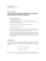
performance evaluation.
First we evaluate the impact of the used bandwidth
on system spectral efficiency. We consider a single user
system where all the available subcarriers in the system
are occupied by the single user. Figure 4 compares the
EURASIP Journal on Wireless Communications and Networking 9
0
−5
5
Average SNR (dB)
10 15 20 25 30 35
Average spectral efficiency (bits/s/Hz)
0
2
4
6
OFDMA
OFDMA, 1.25 MHz
OFDMA, 2.5 MHz
OFDMA, 5 MHz
OFDMA, 10 MHz
OFDMA, 15 MHz
OFDMA, 20 MHz
SC-FDMA
8
10
12
SC-FDMA, 1.25 MHz
SC-FDMA, 2.5 MHz
SC-FDMA, 5 MHz
SC-FDMA, 10 MHz
SC-FDMA, 15 MHz
SC-FDMA, 20 MHz
Figure 4: Comparison of the achievable information rate between
OFDMA and SC-FDMA for different bandwidths under different
average receive SNR conditions in the SCME “urban-macro”
scenario with a single user in the system.
achievable average spectral efficiency between OFDMA and
SC-FDMA for different transmission bandwidths under
different average receive SNR conditions. It can be observed
clearly that for the same average receive SNR, the average
spectral efficiency for SC-FDMA is always smaller than that
for OFDMA, which agrees very well with the analytical
result presented in Section 3.1. Moreover, the achievable
rate for OFDMA almost remains constant for different
transmission bandwidths, while for SC-FDMA it decreases
as the transmission bandwidth increases. This may due to
the fact that as the transmission bandwidth increases and
when it is much larger than the coherence bandwidth, each
time slot consists of a similar number of weak subcarriers.
Since the SC-FDMA rate is mainly constrained by channel
deep fades (more power allocated for weak subcarriers and
less power for good sub-carriers), having similar number of
weaksubcarriersforeachtimeslotislessspectrallyefficient
than having more weak subcarriers for some time slots and
less for the others, where the latter happens in the smaller
bandwidth system with less frequency diversity. On the other
hand, in the OFDMA system, transmit power is equally
allocated in the used subcarriers; therefore, the achievable
rate is insensitive to the distribution of the deep fades over
different time slots.
Then we evaluate the impact of multi-user diversity on
the system spectral efficiency. We assume that a number
of users with the same transmit power constraints simul-
taneously communicate with the BS. Their path loss is
compensated at the BS so that the average receive SNRs
from all the users are the same, which varies from
−20 dB
23
Number of users in the system
456
Average system spectral efficiency (bits/s/Hz)
WF, −20 dB
WF, −10 dB
WF, 0 dB
WF, 10 dB
WF, 20 dB
WF, 30 dB
OFDMA, −20 dB
OFDMA, −10 dB
OFDMA, 0 dB
OFDMA, 10 dB
OFDMA, 20 dB
OFDMA, 30 dB
SC-FDMA, −20 dB
SC-FDMA, −10 dB
SC-FDMA, 0 dB
SC-FDMA, 10 dB
SC-FDMA, 20 dB
SC-FDMA, 30 dB
10
−1
10
0
10
1
Figure 5: Comparison of the achievable system information rate
between OFDMA and SC-FDMA for different numbers of users
under different receive SNR conditions in SCME “urban-macro”
scenario.
to 30 dB in the 20 MHz bandwidth. First, the multi-user
waterfilling (WF) algorithm [15] subject to the individual
power constraint of the users is used to approximate the
multi-user channel capacity, which gives a result close to the
optimal power and subcarrier allocation solution for each
user in the system. Then this subcarrier allocation solution
which implicitly exploits multi-user diversity is adopted for
simulations in both the OFDMA system and the SC-FDMA
system but equal power allocation is used for the transmitted
signal. Figure 5 plots the average system spectral efficiency
over different numbers of users in both the SC-FDMA
system and the OFDMA system under different receive SNR
conditions. It can be seen that the average system spectral
efficiency increases as the number of users in the system
increases in both systems. Due to the multi-user diversity,
the rate loss in SC-FDMA compared to OFDMA decreases
as the number of users increases and it tends to disappear in
high SNR conditions. It should be noted that the subcarrier
allocation solution considered here is still suboptimal for
both systems and a higher sum rate can be achieved in theory.
10 EURASIP Journal on Wireless Communications and Networking
5 MHz5 MHz5 MHz5 MHz
20 MHz
User 1 User 2 User 3 User 4
(a)
0
−5
5
Average SNR (dB)
10 15 20 25 30 35
Average spectral efficiency (bits/s/Hz)
0
2
4
6
OFDMA, 1 Rx
OFDMA, 2 Rx (MRC)
OFDMA, 3 Rx (MRC)
8
10
14
12
SC-FDMA, 1 Rx
SC-FDMA, 2 Rx (MRC)
SC-FDMA, 3 Rx (MRC)
(b)
Figure 6: Comparison of the achievable information rate between
OFDMA and SC-FDMA for different numbers of receive antennas
in SCME “urban-macro” scenario. The system consists of 4 users
with each occupying 5 MHz bandwidth.
Next, we evaluate the impact of spatial diversity on
the system spectral efficiency. We consider that 4 users
communicate simultaneously with the serving BS in the
20 MHz system, where each user occupies 5 MHz bandwidth
as shown in the upper part of Figure 6. The number of receive
antennas at the BS varies from 1 to 3. For multiple antennas,
we assume that maximum ratio combining (MRC) is used in
the frequency domain for both the SC-FDMA and OFDMA
systems. It can be observed that as the number of receive
antenna increases, the rate loss in SC-FDMA compared to
OFDMA decreases significantly due to the channel hardening
effect. Note that the simulation results have not taken into
account the fact that SC-FDMA can further benefit from the
lower PAPR property provided by the consecutive sub-carrier
mapping for each user. Therefore, while being able to achieve
a system sum rate very close to that in OFDMA, SC-FDMA
has an additional lower PAPR advantage.
6. Conclusion
We have presented a framework for an analytical comparison
between the achievable information rate in SC-FDMA and
AM(AB, BC)-
HM(AB, BC)
E
OBB
E
D
A
D
Arithmetic mean (AM)
Harmonic mean (HM)
Geometric mean (GM)
Figure 7: Geometrical interpretation of the harmonic mean,
the arithmetic mean, and the geometric mean of AB(AB
)and
BC(B
C).
that in OFDMA. Ideally, SC-FDMA can achieve the same
information rate as in OFDMA since DFT and IDFT are
information lossless; however, proper coding across the
transmitted signal components and decoding across the
received signal components have to be used. We further
investigated the achievable rate if independent capacity
achieving AWGN codes is used and accordingly decoding is
performed independently among the received components
for SC-FDMA, assuming equal power allocation of the
transmitted signal. A rate loss compared to OFDMA was ana-
lytically proven in the case of frequency selective channels,
and the impact of the weak sub-carriers on the achievable
rate was discussed. We also showed that the achievable
rate in SC-FDMA can be interpreted as performing EGP
allocation among the assigned sub-carriers in the nonpre-
coded OFDMA systems which has a similar geometrical
interpretation with waterfilling. More importantly, it was
pointed out and shown in 3GPP-LTE uplink scenario that the
rate loss could be mitigated by exploiting multi-user diversity
and spatial diversity. In particular, with spatial diversity
we showed that while being able to achieve a system sum
rate very close to that in OFDMA, SC-FDMA provides an
additional lower PAPR advantage.
Appendices
A. Properties of the Circulant Matrix
Fact 1 ([16], Diagonalization of a circulant matrix). Denote
a by the first column of a Q
× Q circulant matrix A and
diag
{·} by the diagonal matrix with the argument on the
diagonal entries, then A can be diagonalized by pre- and
postmultiplication with a Q-point FFT and IFFT matrices,
that is, F
Q
AF
H
Q
= B =
Q diag{F
Q
a},whereB is a Q × Q
diagonal matrix with diagonal entries being a scale version of
the Fourier transform of a.
Fact 2. Because FFT and thus its matrix F
Q
is invertible, it
follows from Fact 1 that
A
= F
H
Q
BF
Q
circulant {a}
,(A.1)
EURASIP Journal on Wireless Communications and Networking 11
where circulant
{a} denotes a circulant matrix with the first
column a.Equation(A.1)meansthatacirculantmatrix
can be written as a multiplication of IFFT matrix, diagonal
matrix, and FFT matrix. In particular, if and only if all entries
of B are equal, then A
= B holds which is also a diagonal
matrix with equal entries.
B. Geometrical Interpretation of
the Harmonic Mean, the Arithmetic Mean,
and the Geometric Mean
Suppose that we want to find out the harmonic mean of
two values, represented by the length of AB and BC (AB <
BC), respectively. By constructing a semicircle with radius
OC
= (AB + BC)/2 as depicted in Figure 7, the harmonic
mean follows directly from the right-angled triangle DBO
and DBE, where the length of DE equals the harmonic mean
of AB and BC,denotedbyHM(AB,BC). It can be observed
that HM(AB,BC)iscomparabletoAB, the smaller value
of the two. In order to show the sensitivity of harmonic
mean to a small value, we can make AB much smaller
than BC but keep AB + BC fixed so that we can use the
same semicircle to find their harmonic mean. Suppose that
AB now becomes AB
and BC becomes B
C as depicted
in Figure 7, following the same way the harmonic mean of
AB
and B
C, that is, HM(AB
,B
C)isgivenbyD
E
.It
can be seen that D
E
is almost comparable to AB
which
is the smaller value of the two. Therefore, the conclusion
can be drawn that the harmonic mean is mainly constrained
by the smaller value AB
although B
C is much larger
than AB
. For comparison purpose, the arithmetic mean
and geometric mean of AB(AB
)andBC(B
C), denoted
by DO(D
O)andBD(B
D
), respectively, are also drawn in
Figure 7. It can easily be seen that if AB
= BC, their harmonic
mean is equal to their arithmetic mean and geometric
mean.
References
[1] D. Falconer, S. L. Ariyavisitakul, A. Benyamin-Seeyar, and
B. Eidson, “Frequency domain equalization for single-carrier
broadband wireless systems,” IEEE Communications Magazine,
vol. 40, no. 4, pp. 58–66, 2002.
[2] N. Wang and S. Blostein, “Comparison of CP-based single
carrier and OFDMA with power allocation,” IEEE Transactions
on Communications, vol. 53, no. 3, pp. 391–394, 2005.
[3] T. Shi, S. Zhou, and Y. Yao, “Capacity of single carrier
systems with frequency-domain equalization,” in Proceedings
of the 6th IEEE Circuits and Systems Symposium on Emerging
Technologies: Frontiers of Mobile and Wireless Communication
(CAS ’04), vol. 2, pp. 429–432, Shanghai, China, May-June
2004.
[4] H. G. Myung, “Introduction to single carrier FDMA,” in
Proceedings of the 15th European Signal Processing Conference
(EUSIPCO ’07), Poznan, Poland, September 2007.
[5] H. Ekstr
¨
om, A. Furusk
¨
ar, J. Karlsson, et al., “Technical solu-
tions for the 3G long-term evolution,” IEEE Communications
Magazine, vol. 44, no. 3, pp. 38–45, 2006.
[6] 3GPP TR 25.814, “3GPP TSG RAN physical layer aspect for
UTRA,” v7.1.0.
[7] V. Jungnickel, T. Hindelang, T. Haustein, and W. Zirwas,
“SC-FDMA waveform design, performance, power dynamics
and evolution to MIMO,” in Proceedings of the IEEE Interna-
tional Conference on Portable Information Devices (PIDs ’07),
Orlando, Fla, USA, March 2007.
[8] H. G. Myung, J. Lim, and D. J. Goodman, “Single carrier
FDMA for uplink wireless transmission,” IEEE Vehicular
Technology Magazine, vol. 1, no. 3, pp. 30–38, 2006.
[9] W. Yu and J. M. Cioffi, “Constant-power waterfilling: per-
formance bound and low-complexity implementation,” IEEE
Transactions on Communications, vol. 54, no. 1, pp. 23–28,
2006.
[10] L. Hoehn and I. Niven, “Averages on the move,” Mathematics
Magazine, vol. 58, no. 3, pp. 151–156, 1985.
[11] S. Cuomo, Pappus of Alexandria and the Mathematics of Late
Antiquity, Cambridge University Press, Cambridge, UK, 2000.
[12] H. Wu and T. Haustein, “Radio resource management for the
multi-user uplink using DFT-precoded OFDM,” in Pro ceed-
ings of the IEEE International Conference on Communications
(ICC ’08), pp. 4724–4728, Beijing, China, May 2008.
[13] R. S. Cheng and S. Verd
´
u, “Gaussian multiaccess channels
with ISI: capacity region and multiuser water-filling,” IEEE
Transactions on Information Theory, vol. 39, no. 3, pp. 773–
785, 1993.
[14] D. S. Baum, J. Hansen, G. Del Galdo, M. Milojevic, J. Salo,
and P. Ky
¨
osti, “An interim channel model for beyond-3G
systems: extending the 3GPP spatial channel model (SCM),”
in Proceedings of the 61st IEEE Vehicular Technology Conference
(VTC ’05), vol. 2, pp. 3132–3136, Stockholm, Sweden, May-
June 2005.
[15] C.Zeng,L.M.C.Hoo,andJ.M.Cioffi,“Efficient water-filling
algorithms for a Gaussian mutliaccess channel with ISI,” in
Proceedings of the IEEE Vehicular Technology Conference (VTC
’00), Boston, Mass, USA, September 2000.
[16] G. H. Golub and C. F. van Loan, Matrix Computations,The
Johns Hopkins University Press, Baltimore, Md, USA, 3rd
edition, 1996.