Báo cáo hóa học: "Research Article Simulation and Emulation of MIMO Wireless Baseband Transceivers" docx
Bạn đang xem bản rút gọn của tài liệu. Xem và tải ngay bản đầy đủ của tài liệu tại đây (19.88 MB, 12 trang )
Hindawi Publishing Corporation
EURASIP Journal on Wireless Communications and Networking
Volume 2010, Article ID 196796, 12 pages
doi:10.1155/2010/196796
Research Article
Simulation and Emulation of MIMO Wireless
Baseband Transceivers
Pierre Greisen, Simon Haene (EURASIP Member), and Andreas Burg (EURASIP Member)
Integrated Systems Laboratory, ETH Zurich Gloriastrasse 35, 8092 Zurich, Switzerland
Correspondence should be addressed to Pierre Greisen,
Received 10 June 2009; Revised 26 October 2009; Accepted 25 November 2009
Academic Editor: Arnd-Ragnar Rhiemeier
Copyright © 2010 Pierre Greisen et al. This is an open access article distributed under the Creative Commons Attribution License,
which permits unrestricted use, distribution, and reproduction in any medium, provided the original work is properly cited.
The development of state-of-the-art wireless communication transceivers in semiconductor technology is a challenging process
due to complexity and stringent requirements of modern communication standards such as IEEE 802.11n. This tutorial paper
describes a complete design, verification, and performance characterization methodology that is tailored to the needs of the
development of state-of-the-art wireless baseband transceivers for both research and industrial products. Compared to the
methods widely used for the development of communication research testbeds, the described design flow focuses on the evolution
of a given system specification to a final ASIC implementation through multiple design representations. The corresponding
verification and characterization environment supports rapid floating-point and fixed-point performance characterization and
ensures consistency across the entire design process and across all design representations. This framework has been successfully
employed for the development and verification of an industrial-grade, fully standard compliant, 4-stream IEEE 802.11n MIMO-
OFDM baseband transceiver.
1. Introduction
State-of-the-art wireless communication systems combine
multiple-input multiple-output (MIMO) technology with
different signaling schemes to increase throughput, link qual-
ity, stability, and range [1]. Unfortunately, the introduction
of MIMO has also lead to a significant increase in the
hardware and system complexity of the baseband signal
processing and has multiplied the number of modes of oper-
ation supported by state-of-the-art wireless communication
standards. MIMO, in conjunction with orthogonal frequency
division multiplexing (OFDM), will be employed in existing
and upcoming standards such as IEEE 802.11n[2], IEEE
802.16e [3], and 3GPP LTE [4].
1.1. From Research Testbeds to Industrial Grade Prototypes.
Since the inception of MIMO, considerable effort has been
dedicated to the demonstration of the capabilities of the tech-
nology and to investigate the performance characteristics of
corresponding transceivers in real-world scenarios. Toward
this goal, various demonstrators and testbeds for MIMO
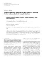
communication have been developed. Figure 1(a) depicts
a common testbed architecture. The heart of the design,
namely, the digital signal processing (DSP), is typically
mapped onto FPGAs [5, 6], sometimes combined with
dedicated application-specific integrated circuits (ASICs) for
performance-critical system components [7], or onto DSP
processors [8–11]. Data converters and a radio frequency
(RF) frontend, equipped with several antennas, interface
to the digital baseband transceiver. The wireless channel
in MIMO testbeds is either a physical channel or a hard-
ware radio frequency (RF) channel emulator. The signal
processing is either performed in real-time or offline. In
the real-time processing case, the samples are processed
at the rate at which they enter the system and the signal
processing meets potential latency requirements. In an off-
line testbed, samples are recorded before and after over-the-
air transmission and the DSP is performed off-line (e.g., in
software) [7, 12–14]. Comprehensive overviews of MIMO
testbeds are for example provided in [15–17].
Such demonstrators and testbeds have been proven to
be instrumental research tools in the early phase of the
development of new technologies [12]: during this early
phase, many factors are still unknown or rely on heavily
2 EURASIP Journal on Wireless Communications and Networking
MAC
layer
(model)
Physical layer (PHY)
Digital signal
processing
FPGA DSP
ASIC
Analog processing
RF
Physical
channel or
channel
emulator
DAC
ADC
(a) Testbed structure
MAC
layer
(model)
Physical layer (PHY)
Digital signal processing
FPGA
ASIC
HDL
SW
Transmit noiseReceive noise
Software
RF
model
TGn
channel
Wav eform
generator
(b) Development and verification environment of this work
Figure 1: Typical testbed architecture 1(a), and this work’s approach 1(b) (for a 4 ×4 MIMO setup).
simplified and yet insufficiently verified theoretical models.
For instance, in the MIMO case, the development and
standardization of wideband MIMO channel models (e.g.,
[18]) has been an iterative process [19, 20]. The ability
to avoid model uncertainties in the early days of a new
technology is the strength and the justification for the devel-
opment of research testbeds. Conversely, one of the draw-
backs of such research testbeds is the lack of reproducibility.
The nondeterministic behavior of the analog part of the
design and the lack of control over the noise and the
real-world wireless channel realization makes it impossible
to fully reproduce or trigger specific test conditions or
events. This lack of control makes a comparison with other
testbeds or products virtually impossible and is a serious
concern for the efficient verification and characterization of
industrial products and for research areas that focus on the
investigation of complexity-performance tradeoffs.
Thanks to the various testbed research contributions, the
knowledge in MIMO communication has reached a level of
maturity that allows proceeding to the development of fully
integrated transceivers that are compliant to standards that
were created for mass products. For the development and
optimization of such products, the testbed approach shown
in Figure 1(a) must be complemented with a verification
environment that delivers fully deterministic and 100%
reproducible results and supports a wide range of additional
verification objectives that are mandatory for product devel-
opment. Such an environment is illustrated in Figure 1(b).
The basic idea is to separate the endeavor to understand and
correctly model the physical environment (using testbeds)
from the system development and characterization process.
In a nutshell, the objective of this paper is to describe
the design and verification process of a standard compliant
baseband transceiver ASIC. In contrast, our previous work
in [5]and[7] describes a testbed setup which is designed to
evaluate the performance of packet-based wireless MIMO-
OFDM transmission under real-world conditions. More
generally, the major difference compared to other testbeds
in the literature (i.e., [5–14, 19, 20]) is the fact that we rely
intentionally on statistical channel models and on models
for the analog/RF circuitry to allow for better reproducibility
and interpretation and comparison of the test results. Also,
the complexity of the setup is considerably reduced, since
no coping with RF implementation intricacies is required.
More on the negative side, the complexity of the software
framework of our testbench is higher than for testbeds, but
not substantially higher. For instance, the time to build the
verification environment described in this paper was roughly
a halfman-year, excluding the actual transceiver.
1.2. Related Design and Verification Methodologies and Tools.
The DSP design flow employed in this work and reviewed
in Section 2.1 involves different design representations,
from MATLAB floating-point to register-transfer-level (RTL)
hardware description language (HDL) (a similar design flow
is described in [21]). To achieve the best possible hardware
efficiency, the refinement from one representation to another
was done manually. Nevertheless, some of the concepts in
the present work rely on the paradigms from the five-
ones approach described in [22]. However, an approach
that adheres more strictly to the five-ones paradigm has
received increasing levels of attention: high-level synthesis
(HLS) (also referred to as behavioral synthesis). The HLS
flow uses one high-level language model (e.g., in ANSI C
or SystemC) and performs resource allocation, mapping,
and scheduling either automatically or semiautomatically,
often based on generic architecture templates. A commercial
solution for HLS is for example Catapult C by Mentor [23].
Design of wireless communication systems using Catapult
EURASIP Journal on Wireless Communications and Networking 3
Common
database
Parameters
Design flow
Floating-point model
Fixed-point model
HDL model
FPGA
ASIC
Model execution, platform
SW (MATLAB) simulation
SW (MATLAB) simulation
HDL simulator
Hardware
Compare results
Figure 2: Design representations for the VLSI development process.
C is described in [24]. Beside the incontestable advantages
described in [24], the automatic approach has two draw-
backs: first, the quality for complex state-of-the-art designs
still cannot be equivalent to the quality obtained by manual
optimization by experienced VLSI designers. Second, the
dependence on a specific commercial tool is often unwanted
for industrial development.
An even higher level approach for describing and veri-
fying complex wireless communication systems starts from
virtual prototypes [25] built from hardware accelerators and
DSPs. The physical layer under consideration in this paper
is merely a single IP component in such a system which
requires a verification strategy by itself. The electronic system
level approach is currently not an option for the baseband
processing itself since it is operating at the limit of modern
process technologies.
1.3. Contributions. This tutorial paper describes the design
flow and a verification and characterization framework
for a standard-compliant industry-grade IEEE 802.11n
transceiver. In particular, we highlight the role of the different
design representations and the importance and structure
of a corresponding verification methodology. Furthermore,
a generic FPGA emulation platform is described, which
provides performance characterization through hardware-
accelerated Monte Carlo simulations.
1.4. Outline. The remainder of this paper is structured as
follows. Section 2 reviews the VLSI design and verification
process used in this work. The different design represen-
tations of the transceiver are introduced and motivated.
Section 3 describes the verification methodology and the
corresponding environment. The focus is on providing
a framework that allows for consistent operation of the
previously introduced design representations. Section 4 deals
with the implementation of the verification framework.
In particular, a generic FPGA emulation architecture is
presented. Section 5 briefly reviews the IEEE 802.11n ref-
erence design and provides implementation figures of the
transceiver in the framework and on the FPGA emulation
platform.
2. Development Process
2.1. Design Flow and Design Representations. Our design flow
for a DSP system [26](Figure 2) starts with the design of
a system-level architecture and the evaluation of suitable
DSP algorithms. The outcome of this initial development
phase is a behavioral floating-point model written in a high-
level programming language (e.g., MATLAB or C/C++). The
subsequent transition to a hardware implementation is a
two-step process. The first step is the refinement of the
floating-point model into a behavioral fixed-point model.
The major effort in this step is the choice of suitable word
widths for all arithmetic operations in the DSP data path.
The second step is the translation of the behavioral fixed-
point model into a corresponding RTL architecture and the
description of that architecture in an HDL such as VHDL
or Verilog. Automatic synthesis and place & route tools then
mapthiscodetoanFPGAortoanASIC.
The most crucial step in the above described design
flow is the floating-to-fixed point conversion, since it has a
significant impact on the final performance of the ASIC com-
pared to the theoretical limit. There are several approaches
to tackle the fixed-point conversion challenge. One can
roughly separate the methodologies into simulation-based
approaches and analytical approaches (and a combination
of both) [27]. For instance, in [28] the floating-point model
is manually converted into a hybrid code model by defining
fixed-point word widths at some “important” locations;
the remaining floating-point values are then interpolated
by analytical means. A similar approach is described in
[27], but optimized for digital signal processor architectures.
The quality of such procedures can be increased by taking
into account the target system performance (e.g., the bit-
error rate specification) and by iterating until the target
performance is achieved [29]. The approach in this work
is similar to [28], but less automated. In essence, word
widths at important block interfaces are defined and all
other values are deduced. However, we infer the remain-
ing values manually, mainly by MATLAB Monte Carlo
simulations or theoretical considerations on the subblock
level. Fine-tuning at the system level is performed through
Monte Carlo simulations based on the HDL implementa-
tion.
4 EURASIP Journal on Wireless Communications and Networking
Table 1: Characteristics of different transceiver simulation models.
Model/Platform Characteristics Scope (used for )
Floating-point/SW Simulation Fast (runtime) Algorithm development
Far from hardware (HW) (data and control path) Reference for other models
Fixed-point/SW Simulation Slow (runtime) Golden model for HDL
Same data path as HW Debug data path
Different control path
Not cycle-true
HDL/Simulator Slow (runtime) Debug control path
Data and control path as in final ASIC Cycle-accurate: determine latencies
HDL/FPGA Fast (runtime) Performance, fixed-point characterization
Accelerated HDL simulation Large coverage of functional runs
Regression runs
2.2. Automated File Generation. Maintaining different design
representations is error-prone [22] when different teams
work in parallel on different representations of the same
block. To overcome this draw-back, the same person is
typically in charge of maintaining all representations of
a single block. On the system-level, automatic conversion
scripts are employed to maintain important parameters such
as data-types, word-lengths, and register address maps in
a single database (Figure 2). This measure together with
regular simulation runs helps to ensure consistency across
different design representations.
2.3. Verification Tasks and Objectives. The development
process described above raises several verification objectives.
(1) Performance Characterization: For large systems, such as
MIMO wireless transceivers, the performance is not known
a priori and can usually not be obtained analytically. Hence,
only statistical evaluation methods can be employed and
results must be reviewed in comparison to the performance
of other candidate algorithms and to solutions known to
be optimal. In general, the corresponding characterization
process requires a large number of Monte Carlo simulations
which are only feasible when simulation runtimes are
sufficiently short.
(2) Fixed-Point Accuracy Analysis: Similar to the first objec-
tive, performance characterization of fixed-point implemen-
tations is realized through Monte Carlo simulations. The
results of these simulations are compared to the results of
corresponding floating-point simulations to determine the
associated implementation loss. Fixed-point design param-
eters are adjusted according to that loss and simulations are
repeated.
(3) Functional Verification: As opposed to the first two
objectives, functional verification is concerned with the
question whether or not an implementation behaves accord-
ing to the behavioral specifications of the system. The
corresponding evaluation is usually carried out based on
a number of predefined testcases for which the expected
response of the system is either known a priori or is
obtained from a known-good reference model. The latter
is often another, more abstract and already sufficiently
verified, design representation against which the current
design representation is compared. A typical example is the
comparison of the HDL model against a software fixed-
point model or the comparison against the behavior of
the floating-point model or against known expected results
under ideal conditions. To achieve sufficienttestcoverage,
functional verification is usually performed with a large
number of meaningful but randomly chosen testcases in
combination with a set of dedicated and carefully selected
testcases [26].
(4) Regression Testing: For larger projects, regular regression
testing must be performed to maintain the integrity of the
design and coherence of the different design representations
over the entire duration of the project.
Ta bl e 1 relates the above described objectives to the
different design representations and to the corresponding
simulation platforms.
3. Verification Environment
3.1. Verification Flow. To meet the different verification
objectives, we propose an automated verification flow shown
in Figure 3 that is tailored to ensure coherence between the
different design representations. The basic concept behind
this flow is to start with a compact testcase definition that is
subsequently expanded into stimuli that are compatible with
all design representations. For each design representation, a
testbench reads these stimuli and records the responses. The
response files are consolidated and forwarded to the final
analysis. The different tasks are described in the following.
(1) Testcase Definition: The starting point for all verification
tasks is the creation of a standardized testcase descriptor
which defines the operations to be carried out on the
transceiver. This description is completely model indepen-
dent, so that any testcase can be executed on any platform
and on all design representations. A simple testcase can for
example stimulate the receiver to process a single incoming
data packet, while more sophisticated testcases can describe
elaborated sequences of interleaved packet transmissions
EURASIP Journal on Wireless Communications and Networking 5
Testcase Stimuli generation
Expected responses
Testbench Testbench Testbench Testbench
Floating-point Fixed-point HDL HDL (FPGA)
Consolidation Consolidation Consolidation Consolidation
Analysis
configuration
Analysis Report
Common
Platform
dependent
Common
Figure 3: Top-Level Verification Flow.
and receptions. Under all circumstances, testcases define
all parameters that are necessary for a simulation. These
parameters include, among others, the random seeds for
the generation of the channel realization through which
a packet is transmitted, the specific noise realization, and
the transmitted payload data. A key benefit of a complete
descriptor is that stimuli generation is fully deterministic and
reproducible, which is a prerequisite to ensure consistent and
reproducible simulation results and is necessary for debug
and regression testing.
In testcases, parameters are defined on a functional level
that is independent of a particular implementation of the
transceiver. Thus, if a specific feature of the transceiver shall
be configured, only a functional abstraction of this setting is
provided in the testcase. This is opposed to directly providing
values for hardware registers, which need to be programmed
in the HDL model but might not exist in other models
or may change as the design evolves. The advantage of
this abstraction is twofold: testcases are completely model
independent and design changes do not affect existing
testcases, reducing the effort for testcase maintenance which
is particularly important for regression testing.
A typical testcase for performance characterization con-
tains a large set of very similar simulation runs, which differ
only in channel realization, noise realization, or received
signal strength. To avoid having a different testcase for each
of these very similar simulation runs, testcases can contain
multiple simulation runs. These runs differ only by few
parameters. The missing notion of relative timing among
simulation runs calls for an even finer grained structure:
each run is again sequenced into phases which can be
timed relative to each other. This is required for functional
verification of sequences of several transmit and/or receive
simulations.
1 setup testcase data structure
2 foreach simulation run do
3 foreach sub-simulation run do
4 sanity check
5 if C on f iguration then
6 configuration parameters: functional to
operational translation
7 if Tx simulation then
generate transmit waveform
8 if Rx simulation then
9 generate receive waveform
10 sequence sub-simulation runs: concatenate
11 and synchronize
12 write concatenated sub-simulation runs to file
Algorithm 1: Stimuli Generation Flow.
(2) Stimuli Generation: Stimuli generation reads the com-
pact, human-readable testcase definition and expands the
testcase into still model-independent stimuli files. To be
independent of the details of the implementation, stimuli
are described at transaction level. Typical transactions are
transceiver configuration, packet transmission, or packet
reception. For each such operation, stimuli files provide the
information required to operate the design under verification
(DUV). The stimuli generation for the testcase structure
described in the previous subsection is summarized by the
pseudocode snippet in Algorithm 1.
(3) Test bench Operation: In order to apply the stimuli to
the different design representations, an environment must
6 EURASIP Journal on Wireless Communications and Networking
Received signal strength indication
Settings for gain stages
RX baseband
samples
Baseband
transceiver
(DUV)
TX baseband samples
RX Playload
data
TX playload
data
Configuration
bus
RF model
Stimuli
Responses
Te s t b e n c h
Monitors
Figure 4: Testbench model.
be created that allows stimulating the inputs of the DUV
and to record the responses at its outputs. Besides the
DUV itself, the environment must also contain all those
components that interact with the DUV and must supply
signals that are specific to a particular design representation
(e.g., clock and reset for an RTL model). The corre-
sponding functionality is provided by a testbench.Ideally,
the same testbench would enable the instantiation of all
design representations to ensure consistency throughout
the entire design process. Unfortunately, this method also
requires the use of a single design-language for all design
representations. Such a single-language approach has the
advantage of allowing for a continuous step-by-step refine-
ment from the original behavioral floating-point model to
the final RTL implementation [22]. However, no single
language is equally well suited for all design representations.
For example, a hardware description language is clearly
ill-suited for algorithm development, while a high-level
language cannot provide the detailed representation of a
parallel architecture that is required to achieve a hardware
efficient silicon implementation. Hence, we shall follow an
approachthatusesmultipledesignlanguagesasdescribed
in Section 2.1. For this approach, consistency of simulations
across all design representations is of utmost importance.
To achieve this objective, individual, compatible testbenches
must be provided as illustrated in Figure 3. By operating
different testbenches from the same stimuli files, different
models can be compared against each other while ensuring
that the same initial conditions apply. This cross verifi-
cation of design representations is indispensable for the
efficient evolution of a design and to ease debugging of
more complicated RTL design representations by compar-
ing them against corresponding behavioral golden models
[26].
(4) Consolidation: The consolidation step translates the
response files, which may differ in their format depending
on the testbench that collected them, into a unified database
appropriate for the subsequent analysis. No intelligence or
interpretation of the data is provided in this step to ensure
robustness against responses from buggy models.
(5) Analysis: The analysis task compares the consolidated
simulation result against system specifications or against a
reference. Such a reference can be obtained from another
simulation run, that is, from the consolidated output of
another design representation, for example, for comparing
fixed-point against HDL simulations. Alternatively, the ref-
erence can consist of expected responses, which are obtained
during stimuli generation. For a packet reception simulation
for example, expected received data bytes can be compared
to the transmitted payload, which is defined in the testcase,
and the modulation and coding scheme detected by the
receiver can be compared to the one specified in the testcase.
The analysis operation itself is defined in a custom way:
a database of analysis plug-ins is available, which can be
instantiated according to the purpose of the testcase and the
verification objective (e.g., calculate and display packet-error
rates).
3.2. Testbench Interfaces for an IEEE 802.11n Transceiver.
Figure 4 shows a top-level testbench for the MIMO-OFDM
baseband transceiver under consideration in Section 5.The
depicted model is applicable to all design representations
of the transceiver that emerge during the entire design
and verification process (fixed-point, floating-point, or RTL
simulation, and FPGA emulation). The testbench instan-
tiates the DUV and a model for the analog RF circuitry
as part of the simulation setup. This model is required
since the RF and the digital transceiver form a closed-loop
in which the baseband samples at the receiver input are
influenced by the settings of the analog gain stages, which are
controlled by the digital transceiver itself. The model of the
RF circuitry is based on an industrial 802.11a RF integrated
circuit. It features two gain stages and outputs complex
baseband signals. The noise-figure is roughly 4–5 dB, but
depends on the gain settings. The model is less accurate
than the analog-HDL description employed for example in
[30], but sufficient to model the key characteristics of the
RF. The testbenches provide the following interfaces to the
transceiver model.
Configuration and control, enabling the configuration of
the transceiver and the management of data transmission
EURASIP Journal on Wireless Communications and Networking 7
and reception.Typically, modulation and coding schemes are
configurable and need to be controlled by the entity in charge
of operating the baseband transceiver. For an RTL model for
example, this corresponds to writing (and possibly reading)
configuration registers.
Analog frontend control interface, enabling the interaction of
the baseband receiver with the analog RF frontend model.
Typically, the baseband processor is in charge of controlling
variable gain stages in the RF circuitry and, in turn, receives
information on the incoming signal strength from the analog
frontend.
Data interfaces, for both transmitter and receiver. In trans-
mit mode, payload data is accepted and baseband samples
are output to the RF. In receive mode, baseband samples are
accepted from the RF, and decoded payload data is output
to the system components in charge of handling the higher
layer protocols.
Monitors, that enable the observation of internal nodes
of the baseband transceiver for the extraction of valuable
debug information. While for software models the concept of
monitors is quite straightforward, the observation of internal
nodes is more involved for hardware design representations
which require dedicated infrastructure to provide access to
these nodes (see Section 4.3).
4. Implementation Aspects
In the previous section, the general verification flow was
introduced. In this section, the implementation of this flow
is described. The focus is on the use of an FPGA emulation
platform for accelerated RTL simulations for functional
verification and for fixed-point performance evaluation.
4.1. Framework and Simulations. The framework of the
verification flow shown in Figure 3 is implemented in
MATLAB. The interfaces to the simulation tasks are stimuli
files stored to disc during stimuli generation. The interfaces
to the consolidation steps are the response files written to disc
during simulation.
The floating-point and fixed-point models of the DUV are
written in MATLAB and hence can be executed directly from
within the verification framework. The HDL model, instead,
is written in synthesizable VHDL. Although started from
within the framework, the HDL simulation is outsourced
to an HDL simulator (Modelsim by Mentor, in our case).
The interaction with this HDL simulator simply consists of
passing the location of the stimuli files as parameters. In
the same way, the HDL testbench is instructed where to
dump the response files, so that the MATLAB framework
knows which responses to process once the HDL simulation
terminates.
FPGA emulation is supported by means of a hardware
driver and dedicated low-layer functions (implemented in a
foreign language interface provided by MATLAB, called mex
functions) that allow stimuli and configuration data to be sent
to the FPGA and responses to be collected from the hardware
through a PCIe bus. The next section discusses the FPGA
testbenchinmoredetail.
4.2. FPGA Emulation Platform. The main motivation for an
FPGA emulation platform is the slow simulation speed of
the fixed-point model and of the HDL design representation
running on the HDL simulator platform. This slow simula-
tion speed renders large amounts of bit-accurate simulations
impractical. The emulation on FPGAs is a relatively low-
cost alternative to dedicated hardware accelerators. FPGA
emulation enables
(i) Monte Carlo simulations for performance character-
ization (e.g., for the extraction of bit-error rates or
packet-error rates),
(ii) extensive functional verification runs with a large
number of dedicated and random tests, to achieve
high test coverage, and
(iii) regression testing by checking whether new features
or bug-fixes affect test results and to ensure coherence
between the RTL code and other design representa-
tions.
An overview of the proposed FPGA testbench, compris-
ing the FPGA infrastructure and the software, is provided in
Figure 5. The depicted setup essentially corresponds to the
testbench in Figure 4, implemented on an FPGA platform
and on a host PC.
A bus bridge translates the PCIe protocol into the specific
protocol supported by the configuration interface of the
DUV. The other stimuli are sent from the host PC over
the PCIe bus to dedicated stimuli port adapters which apply
the data to the input ports of the DUV. Responses from
the DUV are collected by response port adapters and are
forwarded to the host PC. The number of port adapters is
determined by the number of interfaces of the DUV and can
be configured at synthesis time. A user-defined portion of
the memory space, accessible from the host PC, is assigned
to each port adapter. Port adapters are essentially FIFOs with
configurable word widths designed to exhibit a handshake
data interface for the application of stimuli and for the
collection of responses. Type conversion functions translate
the bit-vector outputs of the port adapters into arbitrary
HDL data types used for the I/O ports of the DUV when
applying stimuli, and vice versa when collecting responses.
Theconversionrequiresnohardwareoverhead.
The FIFOs in the port adapters are composed of three
sub-FIFOs as shown in Figure 6. In stimuli port adapters, the
first FIFO is built from on-FPGA SRAM macros. It accepts
stimuli data from the PCIe controller and forwards this data
to the second FIFO which is implemented on an external
SDRAM module allowing for larger storage capacities. From
the SDRAM FIFO, data is forwarded to the third FIFO,
which is again realized on the FPGA. This third FIFO
eventually pushes the stimuli into the DUV. For the response
port adapters, a similar concept is implemented with the
three FIFOs shuffling data in the opposite direction (from
the DUV to the PCIe). In the proposed implementation,
8 EURASIP Journal on Wireless Communications and Networking
SDRAM
Port
adapter
Port
adapter
Port
adapter
Type
cast
Type
cast
Type
cast
RF model
Stimuli Responses
DUV
.stim
.resp
Bus
bridge
PCle core & logic
C-functions and driver
Mex-function
MATLAB
Host PC
FPGA top level
.
.
.
.
.
.
Figure 5: FPGA emulation testbench. The number of port adapters depends on the number of interfaces of the DUV.
multiple port adapters share a single PCIe connection and
a single SDRAM module for the realization of their external
FIFOs. To avoid bandwidth bottlenecks at these interfaces,
the corresponding interface clocks must be kept as high as
possible, while the clock of the DUV must be adjustable
to facilitate the mapping and timing closure of the ASIC
design on the FPGA. (Note that in most cases the DUV
targets an ASIC process so that its architecture is ill-suited
to achieve real-time operation on an FPGA. Hence, FPGA
emulation typically runs at a fraction of the ASICs target
clock frequency).
One drawback of the FPGA emulation is the long
implementation time for large designs. To alleviate this
issue and to make the system scalable to designs with
higher complexity (e.g., using better receivers), the DUV
can be partitioned over multiple FPGAs. The handshake
interfaces between the blocks allow for putting an entire
block on a second FPGA while routing the corresponding
interfaces via FPGA interconnections. In this way, a block
which is currently under construction can be implemented
independently of the rest of the design (provided that the
interfaces do not change). An automatic partitioning flow
can also be set up using Certify [31], for instance.
4.3. Monitoring of Intern al Nodes. The monitoring of inter-
nal nodes of the design for debugging and analysis is an
important requirement. During MATLAB or HDL simula-
tion, instantiated monitors can simply dump data according
to a configuration file that selectively enables or disables
monitors. However, for FPGA emulation or even for the
final ASIC, providing sufficient visibility into the design is
a major challenge. In order to solve this problem, the DUV
is equipped with a debug output port, whose bit-width can
be configured at synthesis time. Internal nodes connected
to monitors can be multiplexed to this port. Which node is
observed can be configured using the configuration interface
of the transceiver. If a particular node to be observed is wider
than the debug port, several addresses are assigned to this
node. Each address corresponds to a bit-slice of the node.
In this case, multiple simulations must be carried out to
reconstruct the complete signal, collecting a different bit-
slice during each simulation. The data from the monitors is
collected and consolidated together with other responses.
5. Application to IEEE 802.11n
In this case-study, the design under verification is a full
IEEE 802.11n standard compliant MIMO-OFDM baseband
transceiver. The digital signal processing part has been
fabricated in 130 nm technology and is described in [32]. The
main characteristics of the 802.11n transceiver are summa-
rized in Tab le 2. A top level block diagram of the transceiver
is provided in Figure 7. The transmit chain consists of three
main blocks: the input data is the payload in octets, the
output data is the baseband samples to be transmitted.
The channel coding block contains a rate 1/2 convolutional
encoder followed by a puncturer to obtain different coding
rates (2/3, 3/4, and 5/6) and a bit-interleaver. The space
time processing block first maps bits to complex valued
constellation points (BPSK, QPSK, 16-QAM, or 64-QAM),
then inserts zero and pilot tones for OFDM modulation.
The output is then OFDM modulated using an inverse fast
EURASIP Journal on Wireless Communications and Networking 9
Clock domain 1 Clock domain 2 Clock domain 3
SDRAM
PCle controller
Stimuli port adapter
FIFO1 FIFO2 FIFO3
FIFO1FIFO2FIFO3
DUV
Figure 6: Structure of port adapters.
1
8
24
8
TX BB samples
PA
Tr ig ger
PA
Noise samples
PA
RX BB samples
PA
8
∗
12 8
∗
12
RF model
8
∗
12
8
∗
12
TD processor
Tx controller
OFDM modulation
FD processor
Rx ST processing
Rx channel coding
TX payload Monitor RX payload
Rx channel coding
Rx controller
Rx ST processing
Rx channel coding
PA PA PA
Configuration and control Transmit data path Receive data path
Configuration bus
Figure 7: MIMO-OFDM Transceiver Overview.
Fourier transform (IFFT) shared with the receive chain. Prior
to demodulation, the receiver needs to process the received
signals in the time domain: frame start detection, frequency
offset estimation, and digital gain control are the main tasks.
After the FFT, the Rx ST processing block demaps the received
signals. The output is then deinterleaved, depunctured, and
decoded using a Viterbi decoder.
The different coding rates, modulation schemes, and
number of spatial streams are described by modulation and
coding schemes (MCS) and are defined in the IEEE 802.11n
10 EURASIP Journal on Wireless Communications and Networking
Table 2: Key figures of the 802.11n design [32]ondifferent
platforms.
130 nm ASIC
Virtex-5 LX330
FPGA
Tx/Rx antennas 4 4
Modes [2] MCS 0–31 MCS 0–31
Bandwidth 20–MHz, 40–MHz 20–MHz, 40–MHz
Guard Interval (GI) short, long short, long
Operating speed 160–MHz 20 MHz
Throughput 6 600 Mbps (not real-time)
Area 1757 kGE
≈ 75% (Tab le 3)
standard [2]. The transceiver handles up to four spatial data
streams with four antennas both at the transmitter and at
the receiver. The design supports a total of 76 MCSs, most of
them both in 20 MHz channels (data rates up to 289 Mbit/s)
and in 40 MHz channels (data rates up to 600 Mbit/s), with
short or long guard interval, in two different packet formats
(Greenfield and mixed format), giving rise to hundreds of
modes of operation.
The different blocks of the transceiver are arranged
linearly and attached to each other by handshake interfaces.
This processing paradigm holds not only for the top level
blocks shown in Figure 7, but also across all levels of
hierarchy. The handshake interfaces allow operating the top-
level of the design (as well as the lower hierarchies) at
transaction-level. In addition to the welcome side-effect, that
plugging in new or revised blocks into the design is much
easier with a standardized handshake interface, the operation
of different design representations is simplified considerably.
In fact, transaction-level operation is equally well suited
for timed (e.g., RTL models) and untimed (e.g., MATLAB
models) design representations and eases the design of
the corresponding testbenches. For instance, transaction-
based stimuli alleviate the FPGA emulation, since cycle-
accurate delivery of the stimuli is not required which
relaxes the requirements on the corresponding testbench
implementation.
In our baseband-transceiver case study, port adapters are
used to transfer baseband samples, thermal noise samples,
transmit and receive payload data, and to monitor internal
nodes of the design. For debugging purposes, a (one bit)
frame start trigger signal is available in a separate port
adapter. The clock frequency of the SDRAM was set to
133 MHz and the clock frequency of the PCIe core was
set to 65 MHz. The DUV interfaces operate at 20 MHz,
which corresponds to 1/8 of its real-time target clock
frequency achieved on a dedicated 130nm CMOS ASIC
process. The configuration interface of the DUV is a stan-
dardized advanced microcontroller bus architecture (AMBA)
advanced high-performance bus (AHB) which is connected
in the FPGA testbench through a PCIe-to-AHB bridge. The
system has been realized on a HAPS-52 [33] prototyping
board by Synplicity (now Synopsis) featuring two Virtex-
5 LX330 FPGAs, a plug-in SDRAM board, and a PCIe
interface. The entire setup is realized on one of the two
Table 3: FPGA resources (total and relative to available).
Registers Lookup Tables
Port adapters (7 instances) 9148 (4.4%) 8770 (4.2%)
PCIe 6823 (3.3%) 7853 (3.8%)
802.11n design 74723 (36.0%) 166541 (80.3%)
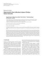
Figure 8: Verification environment software (on the screen: graph-
ical user interface (GUI) and result plots) and FPGA emulation
platform.
FPGAs. The corresponding resource utilization of the FPGA
is summarized in Ta ble 3. The utilization is specified relative
to the resources available in one of the two Virtex-5 LX330
FPGAs [34] available on the HAPS-52 prototyping board. A
picture of the test setup is shown in Figure 8, containing the
graphical user interface (GUI), monitor output of received
signal constellation points, packet-error rate curve, and a
HAPS-52 board connected via PCIe to the host PC.
Compared to HDL simulation, the FPGA platform
achieves a speed-up of two to three orders of magnitude.
While the clock frequency of the DUV on the FPGA
could easily be increased, the main performance bottleneck
is due to the file handling operations in MATLAB. The
MATLAB fixed-point simulation has a simulation speed
that is comparable to the HDL simulation. Compared to
FPGA emulation, the behavioral MATLAB floating-point
simulation is slightly slower, but on the same order of
magnitude. Note that with the proposed monitoring strategy
the collection of large amounts of monitor data potentially
decreases simulation speed on the FPGA significantly. This
is because the number of reserved monitor output pins on
the DUV is limited, so that for the observation of wider
internal nodes or when monitoring several different internal
nodes, the same simulation has to be run several times to
collect the required bit-slices. Moreover, activated monitors
also decrease the simulation speed of MATLAB simulations,
due to additional file handling operations. A typical 802.11n
packet reception on the FPGA emulation takes 0.1 to 2
seconds, depending on the packet size and modulation
scheme.
EURASIP Journal on Wireless Communications and Networking 11
6. Conclusions
Wireless communication testbeds have been instrumental for
the investigation of the propagation environment in modern
wireless communication systems and for early demonstra-
tions of the technology. However, the testbed approach
is often ill-suited for the VLSI development of industrial
and standard-compliant products. The aim of this tutorial
paper was to describe a design and verification methodology
for wireless communication transceivers. The described
approach is based on multiple design representations such as
floating-point models, bit-accurate behavioral models, and
register transfer level descriptions. To ensure consistency
across these different design representations, a common
verification framework is required. The described framework
delivers consistent and 100% reproducible results. For the
rapid fixed-point performance characterization, FPGA emu-
lation is integrated into this framework using a generic FPGA
emulation platform.
Acknowledgments
The authors gratefully acknowledge the entire team of
Celestrius Inc. Special thanks go to U. Schuster who played
a major role in both designing and implementing the
framework. Financial support from the Swiss National
Science Foundation under project number PP002-119052 is
also gratefully acknowledged.
References
[1] G. J. Foschini and M. J. Gans, “On limits of wireless com-
munications in a fading environment when using multiple
antennas,” Wireless Personal Communications,vol.6,no.3,pp.
311–335, 1998.
[2] IEEE draft P802.11n/D2.0, “Wireless LAN MAC and PHY
specifications: enhancements for higher throughput,” New
York, NY, USA, February, 2007.
[3] IEEE 802.16e-2005, “Local and metropolitan networks—part
16: air interface for fixed and mobile broadband wireless access
systems, amendment 2: physical and medium access control
layers for combined fixed and mobile operation in licensed
bands and corrigendum 1,” 2006.
[4] “E-UTRAN: physical channels and modulation,” 3GPP Std. TS
36.211, March 2009.
[5] S. Haene, D. Perels, and A. Burg, “A real-time 4-stream
MIMO-OFDM transceiver: system design, FPGA implemen-
tation, and characterization,” IEEE Journal on Selected Areas in
Communications, vol. 26, no. 6, pp. 877–889, 2008.
[6] P. Murphy, F. Lou, A. Sabharwal, and J. P. Frantz, “An FPGA
based rapid prototyping platform for MIMO systems,” in
Proceedings of the 37th Asilomar Conference on Signals, Systems
and Computers (ACSSC ’03), vol. 1, pp. 900–904, Pacific Grove,
Calif, USA, November 2003.
[7] M. Wenk, P. Luethi, T. Koch, et al., “Hardware platform
and implementation of a realtime multi-user MIMO-OFDM
testbed,” in Proceedings of the IEEE International Symposium
on Circuits and Systems (ISCAS ’09), pp. 789–792, May 2009.
[8] S. Caban, C. Mehlf
¨
uhrer, R. Langwieser, A. L. Scholtz, and M.
Rupp, “Vienna MIMO testbed,” EURASIP Journal on Applied
Signal Processing, vol. 2006, Article ID 54868, 13 pages, 2006.
[9] T. Haustein, A. Forck, H. Gabler, V. Jungnickel, and S.
Schiffermuller, “Real-time signal processing for multiantenna
systems: algorithms, optimization, and implementation on an
experimental test-bed,” EURASIP Journal on Applied Signal
Processing, vol. 2006, Article ID 27573, 21 pages, 2006.
[10] R. Mostafa, R. Gozali, R. C. Palat, et al., “Design and
implementation of a DSP-based MIMO system prototype for
real-time demonstration and indoor channel measurements,”
EURASIP Journal on Applied Signal Processing, vol. 2005, no.
16, pp. 2673–2685, 2005.
[11] J. W. Wallace, B. D. Jeffs, and M. A. Jensen, “A real-
time multiple antenna element testbed for MIMO algorithm
development and assessment,” in Proceedings of the IEEE
Antennas and Propagation Society Symposium, vol. 2, pp. 1716–
1719, Monterey, Calif, USA, June 2004.
[12]M.Rupp,C.Mehlf
¨
uhrer, S. Caban, R. Langwieser, L. Mayer,
and A. Scholtz, “Testbeds and rapid prototyping in wireless
system design,” EURASIP Newsletter, vol. 17, no. 3, pp. 32–50,
2006.
[13] D. Ram
´
ırez, I. Santamar
´
ıa, J. P
´
erez, et al., “A flexible testbed
for the rapid prototyping of MIMO baseband modules,” in
Proceedings of the 3rd International Symposium on Wireless
Communication Systems (ISWCS ’06), pp. 776–780, Valencia,
Spain, September 2006.
[14] R. M. Rao, S. Lang, and B. Daneshrad, “Field measurements
with a 5.25 GHz broadband MIMO-OFDM communication
system,” IEEE Transactions on Wireless Communications, vol.
6, no. 8, pp. 2848–2859, 2007.
[15] J. Garcıa-Naya, M. Gonz
´
alez-L
´
opez, and L. Castedo, “An
overview of MIMO testbed technology,” in Proceedings of the
4th International Symposium on Image and Video Communi-
cations over Fixed and Mobile Networks (ISIVC ’08), Bilbao,
Spain, July 2008.
[16]T.Kaiser,A.Wilzeck,M.Berentsen,andM.Rupp,“Proto-
typing for MIMO systems-an overview,” in Proceedings of the
12th European Signal Processing Conference (EUSIPCO ’04),
pp. 681–688, Vienna, Austria, September 2004.
[17] R. M. Rao, W. Zhu, S. Lang, et al., “Multi-antenna testbeds
for research and education in wireless communications,” IEEE
Communications Magazine, vol. 42, no. 12, pp. 72–81, 2004.
[18] V. Erceg, et al., “TGn Channel Models,” IEEE 802.11 document
03/940r4.
[19] P. Goud Jr., R. Hang, D. Truhachev, and C. Schlegel, “A
portable MIMO testbed and selected channel measurements,”
EURASIP Journal on Applied Signal Processing, vol. 2006,
Article ID 51490, 10 pages, 2006.
[20] A. I. Fabregas, M. Guillaud, D. Slock, et al., “A MIMO-OFDM
testbed for wireless local area networks,” EURASIP Journal on
Applied Signal Processing, vol. 2006, Article ID 18083, 20 pages,
2006.
[21] J W. Weijers, V. Derudder, S. Janssens, F. Petre, and A.
Bourdoux, “From MIMO-OFDM algorithms to a real-time
wireless prototype: a systematic matlab-to-hardware design
flow,” EURASIP Journal on Applied Signal Processing, vol. 2006,
Article ID 39297, 12 pages, 2006.
[22] M. Rupp, A. Burg, and E. Beck, “Rapid prototyping for
wireless designs: the five-ones approach,” Signal Processing,
vol. 83, no. 7, pp. 1427–1444, 2003.
[23] M. Graphics, “Catapult C synthesis,” tor.
com/.
[24] Y. Guo, D. McCain, J. Cavallaro, and A. Takach, “Rapid
industrial prototyping and SoC design of 3 G/4 G wireless
systems using an HLS methodology,” EURASIP Journal on
Embedded Systems, vol. 2006, Article ID 14952, 25 pages, 2006.
12 EURASIP Journal on Wireless Communications and Networking
[25] P. Belanovic, B. Knerr, M. Holzer, and M. Rupp, “A fully
automated environment for verification of virtual prototypes,”
EURASIP Journal on Applied Signal Processing, vol. 2006,
Article ID 32408, 12 pages, 2006.
[26] H. Kaeslin, Digital Integrated Circuit Design, Cambridge
University Press, Cambridge, UK, 2008.
[27] D. Menard, D. Chillet, and O. Sentieys, “Floating-to-fixed-
point conversion for digital signal processors,” EURASIP
Journal on Applied Signal Processing, vol. 2006, Article ID
96421, 19 pages, 2006.
[28] M. Coors, H. Keding, O. Luthje, and H. Meyr, “Design
and DSP implementation of fixed-point systems,” EURASIP
Journal on Applied Signal Processing, vol. 2002, no. 9, pp. 908–
925, 2002.
[29] D. Menard, R. Serizel, R. Rocher, and O. Sentieys, “Accu-
racy constraint determination in fixed-point system design,”
EURASIP Journal on Embedded Systems, vol. 2008, Article ID
242584, 12 pages, 2008.
[30] E. Morales, G. Zucchelli, M. Barnasconi, and N. Jugessur,
“Novel methodology for functional modeling and simulation
of wireless embedded systems,” EURASIP Journal on Embed-
ded Systems, vol. 2008, Article ID 171358, 9 pages, 2008.
[31] Synopsys, “Certify,” />tion/HardwareAssistedVerification/Confirma/Pages/Certify
.aspx.
[32] A. Burg, S. Haene, M. Borgmann, et al., “A 4-stream 802.11n
baseband transceiver in 0.13 µm CMOS,” in Proceedings of the
IEEE Symposium on VLSI Circuits, pp. 282–283, June 2009.
[33] Synplicity, “HAPS-52 Virtex-5 Motherboard,” http://www
.synopsys.com/Tools/Verification/HardwareAssistedVerifica-
tion/Documents/haps-52-ds.pdf.
[34] Xilinx, “Virtex-5 family overview,” />support/documentation/data
sheets/ds100.pdf.