Báo cáo hóa học: "Research Article OMNeT++-Based Cross-Layer Simulator for Content Transmission over Wireless Ad Hoc Networks" pot
Bạn đang xem bản rút gọn của tài liệu. Xem và tải ngay bản đầy đủ của tài liệu tại đây (2.16 MB, 12 trang )
Hindawi Publishing Corporation
EURASIP Journal on Wireless Communications and Networking
Volume 2010, Article ID 502549, 12 pages
doi:10.1155/2010/502549
Research Article
OMNeT++-Based Cross-Layer Simulator for
Content Transmission over Wireless Ad Hoc Networks
R. Massin, C. Lamy-Bergot, C. J. Le Martret, and R. Fracchia
EDS/SPM and SEA Departments, Thales Communications, Colombes 92704, France
Correspondence should be addressed to R. Massin,
Received 1 June 2009; Accepted 24 November 2009
Academic Editor: Nikos Passas
Copyright © 2010 R. Massin et al. This is an open access article distributed under the Creative Commons Attribution License,
which permits unrestricted use, distribution, and reproduction in any medium, provided the original work is properly cited.
Flexbility and deployment simplicity are among the numerous advantages of wireless links when compared to standard wired
communications. However, challenges do remain high for wireless communications, in particular due to the wireless medium
inherent unreliability, and to the desired flexibility, which entails complex protocol procedures. In that context simulation is an
important tool to understand and design the protocols that manage the wireless networks. This paper introduces a new simulation
framework based on the OMNeT++ simulator whose goal is to enable the study of data and multimedia content transmission over
hybrid wired/wireless ad hoc networks, as well as the design of innovative radio access schemes. To achieve this goal, the complete
protocol stack from the application to the physical layer is simulated, and the real bits and bytes of the messages transferred on the
radio channel are exchanged. To ensure that this framework is reusable and extensible in future studies and projects, a modular
software and protocol architecture has been defined. Although still in progress, our work has already provided some valuable
results concerning cross layer HARQ/MAC protocol performance and video transmission over the wireless channel, as illustrated
by results examples.
1. Introduction
The recent years have seen the explosion of new wireless
networking solutions design and corresponding first deploy-
ments in real life. Those systems, taking advantage of the
mobile devices and computers ever increasing capabilities,
are becoming more and more complex, as can be seen by
comparing the recently standardized WiMAX [1]withits
WiFi ancestor [2]. One of the reasons for the aforementioned
complexity increase is the apparition of cross-layer and
cooperative design instead of the previously strictly separated
Open System Interconnection (OSI) reference model layers
definition. It follows that the use of monolithic C code
simulation is no longer well suited to the evaluation of new
waveform designs encompassing several research domains
and layers. Cross-layer simulation in particular, either con-
sidered for intelligent Data Link and PHY codesign [3, 4]or
for a more general complete cross-layer design [5], naturally
entails the usage of complex simulation systems, which offer
the capability to jointly optimize several modules of the
complex transmission scheme.
Different works have shown recently, for example, [6]
the number and variety of system simulators, as well as
their evolution and growing usage. The purpose of our
work is, thus, not to define or develop a new simulator
that would eventually be better attuned to our specific
goals, but to develop a generic framework over an existing
simulation tool. Indeed, the development of a new simulator
would require a complete system design and would raise
the difficult question of system maintenance. The viability
of such tools, as for instance YANS [7], is dubious if
the users community is not strong enough to maintain
and let them coherently evolve with the research state
of the art. Along the lines of the Mobility Framework
[3], we have developed a generic framework built on the
OMNeT++ [8] simulation tool only using its most basic
and generic features (e.g., discrete event scheduling) and
simple and easily reusable C/C++ code implementation.
We have made this choice to ensure that this framework
completely fits our purpose, that is, the establishment of
a generic architecture to simulate transmission of data
and multimedia content over hybrid wired/wireless ad hoc
2 EURASIP Journal on Wireless Communications and Networking
networks and the design of innovative radio access schemes.
Thanks to this approach, that was used in parallel for the two
independent projects DITEMOI [9] and RISC [10] of the
French National Research Agency (ANR) the integration of
a complete radio access layer with the peer-to-peer oriented
video data transmission solution could be merged and jointly
exploited.
This paper is organized as follows. Section 2 presents
the design principles established for the simulation chain
realization, including the overall protocol architecture and
examples of interfaces. Section 3 details specific realizations
done to ensure the feasibility of high-fidelity simulations
when dealing with cross-layering solutions for wireless
ad hoc networks. Section 4 presents some examples of
the experimental results that can be obtained with this
framework, while explaining their interest and possible usage
for real systems definition. Finally, conclusions are drawn in
Section 5.
2. Simulation Chain Principle and Design
2.1. High-Fidelity Simulations with OMNeT++. As said
before, we consider in this paper the event-driven discrete
time simulation tool OMNeT++ as our reference frame-
work. Nevertheless, the approach proposed could be easily
extended to other comparable tools such as OPNET [11]or
even NS-2 [12].
OMNeT++ has two main characteristics that allow to
design the models used to validate network communication
protocols in an efficient and cost reasonable way. The first
one is its capability to allow an easy definition, through
text files, of protocol architecture and information exchange
between protocol layers. The second and most important
aspect is that it handles each event in sequence and maintains
its own simulated time clock. This clock is only updated
at the end of all the treatments associated to the events
to be handled at the current time. This property is of
great interest in complex systems simulation, as it allows to
remove all problems related to real-time and synchronization
constraints.
Nevertheless, the classical approach of OSI layers separate
design, reinforced by the specialization of most researchers
on a part of the protocol stack, has led to define frame-
works for OMNeT++ that enter in deep details for given
layers, while making strong assumptions for the other
ones. This is especially true for higher (e.g., application)
and lower (e.g., physical) layers. Particularly, it can be
observed that, even if this is evolving [4, 13], standard
existing frameworks over OMNeT++ [3, 14]relyona
quite simple abstraction of the physical layer. It is usual to
estimate packet error rate after channel decoding by simply
drawing a random variable. We believe that building up
an efficient cross-layer design enabled data link layer over
such a simplified physical layer model leads in practice
to questionable results. Indeed, due to the high number
of variable parameters such as received power, number
of interfering signals, multipath, and so forth, such a
simulator is not adapted to perform detailed and reliable
simulations.
Simulations allowing to obtain such fine detail level
are conventionally referred to as High-Fidelity Simulation
(HFS) [6]. The HFS approach is necessary to assess the
performance of communication systems designed in a cross-
layer way that may encompass the whole protocol stack from
the application layer to the physical layer. As a matter of
fact, when simulating end-to-end systems that may include
wireless relay nodes such as in ad hoc networks, precise and
realistic simulation of the numerous mechanisms derived to
enhance the link reliability must be performed, in particular
to determine how their effects can be combined and what is
their joint gain. Indeed, mechanisms such as Hybrid Auto-
matic Repeat Request (HARQ) [15] at the data link layer or
TCP at the transport layer share the same goal of combating
losses or errors occurring in the network. They both use
similar techniques of retransmission, and consequently do
not satisfy the independence conditions that would allow to
separately add their gains. Furthermore, when considering
the transmission of multimedia data [16, 17], in particular
over unreliable protocols such as UDP or UDP-Lite, the
resilience of advanced decoders can be used to overcome
remaining errors or losses thanks to concealment. For such
applications, where codecs are operating on real data bit
strings and can tolerate some errors or small packet losses,
modeling the system at high level is limitative. Typically, this
approach will lead to obtain only capacity evaluations but no
actual quality measurements, as in [18]. The unequal relative
importance of different portions of the multimedia bitstream
also justifies an HFS approach, to ensure that the measured
perceived quality of service (PQoS) at the application level
is representative. This is even more critical when mecha-
nisms at higher layers behave according to the information
coming from lower layers, such as the packet error rate
at transport level, the channel state information [5], the
perceived effect of the interference for link adaptation, or
spectrum aware routing as in the Cognitive Radio paradigm
[19].
In the following, we explain how we have implemented
an HFS simulation with OMNeT++, modeling each layer in
detail by working at bit level, as described in Section 3.1.
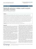
2.2. Protocol Stack Organization. Figure 1 depicts the overall
protocol architecture that is considered in this paper. Our
objective being to define a generic ad hoc architecture with
multiple nodes that would be used in a global simulation, we
have defined two levels of components:
(i) global components, which allow to drive the simu-
lation and have global knowledge about the whole
network. The first one is the connectivity manager
which determines, for each node of the network, the
nodes in its range. The other one is the radio channel
manager in charge of determining channel effects (see
Section 3.2.2),
(ii) local components, which are the protocol entities
within the network node. Each such node may be a
base station, a mobile station, or even a data server.
To accurately simulate the transmission of data and
multimedia content, the node model covers five of the seven
EURASIP Journal on Wireless Communications and Networking 3
OSI #7 layer
(application)
OSI #4 layer
(transport)
OSI #3 layer
(network)
OSI #2 layer
(data link)
OSI #1 layer
(physical)
Connectivity
manager
Radio channel
manager
Global
components
Node n
Node 2
Node 1
Source coding
RTSP
RTP
UDP (-lite)/TCP
IP
ROHC/SAR/Q
MAC
FEC
Modem
Tx Rx
TSM
XLI
Routing
protocol
HARQ
Local
components
for each
node in the
network
Routing
table
Figure 1: Overall protocol architecture.
layers of the OSI reference model, having all the same generic
format. However, the nodes can be specified separately
(i.e., given specific protocols capabilities) in particular via
the usage of OMNeT++ specific initialization parameters.
Typically, multimedia source and receiver nodes will be
able to use RTSP requests for RTP encapsulated video data
transmission over UDP(-Lite)/IP sockets while data source
and receiver nodes may use TCP/IP sockets. Similarly, Robust
Header Compression (RoHC) or specific Segmentation and
Reassembly (SAR) layers can be selected when needed.
Finally, as in [20] a transverse module, denoted as XLI for
cross-layer interface, has been introduced in each node of the
system to allow the joint optimization of several layers.
This approach follows the recent trend showing that
the traditional separate decoding of source and channel
codes can be efficiently replaced by overall end-to-end
optimization [21].
2.3. Interfaces. Generic interfaces to exchange information
across the protocol stack have been defined.
2.3.1. D a ta Path. From application to physical layer, each
protocol entity receives data messages from its upper inter-
face and forwards them to its lower interface. In a way similar
to what is done in the Mobility Framework [3] a software API
(Application Programming Interface) has been defined to
send and receive information on the data path: sendDown()
and sendUp() are used to send data to the lower and upper
layers, and handleLowerMsg() and handleUpperMsg() are
used to receive data from the lower and upper layers.
What is particular in the proposed framework is that on
the data path the bits and bytes of the messages are really
transmitted, as detailed in Section 3.1.
2.3.2. Control Information Exchange. Cross-layer optimiza-
tions are made possible through exchange of signaling
information along the protocol stack. In our framework this
is done through the XLI, which can be seen as a message
switch enabling communication between all layers on the
same network host: ControlMessage messages are sent to the
XLI from one source layer and forwarded by the XLI to the
destination layer. All possible destinations are identified by a
unique number to allow XLI operation. This scheme allows
any protocol layer to use a single s endControl() method
with a ControlMessage as parameter, to transmit signaling
information across the local protocol stack. Of course,
object inheritance is used and the transferred message is
in fact derived from ControlMessage, containing the proper
information. An example of such derived message is the
QueueCreateNewNeighbourMessage defined as follows (using
OMNeT++ .msg format):
message QueueCreateNewNeighbourMessage
extends ControlMessage
{
fields:
int idNeighbour;
int nbPriorities;
};
4 EURASIP Journal on Wireless Communications and Networking
BytesMsg →memoryArea
+
IP header
= 20 bytes
UDP header
= 8bytes
User data
+
BytesMsg
→pduBytes
BytesMsg
→memoryAreaBytes
BytesMsg
→pduBytes =
BytesMsg →memoryArea + (BytesMsg →memoryAreaBytes − BytesMsg →pduBytes)
Figure 2: Example of Application Programming Interface: transmitting real bits.
This message is used to create nbPriorities new queues when
a new one-hop neighbor (whose address is idNeighbour)
has been detected. A similar message exists to destroy
these queues when the node vanishes from the one-hop
neighborhood.
3. Specific Realizations
This section first presents the mechanism and API used to
transfer bits between protocol layers and between network
nodes. Then the flexible and modular approach followed
in our framework is discussed. Finally, two examples of
sequence diagrams are reported to illustrate specific realiza-
tions.
3.1. Working at Bit Level. Modeling communications at
bit level allows to finely take into account the effect of
the wireless channel at all protocol layers. Moreover, this
level of detail is required to simulate some communication
schemes. For example in the ANR RISC project LDPC error
correcting codes are used to improve the quality of wireless
communications over a CDMA UWB channel [22]. Since the
interference noise perceived on the UWB channel depends
on the number of interferers and their signal level which
constantly change during the simulations, it is extremely
difficult to assess the performance of such codes without
really running the LDPC codec within the simulation. To
do this, bit-level modeling is needed at the PHY layer.
Another example concerns the ANR DITEMOI project.
There, video codecs resilient to residual errors are studied,
implying the need of bit-level modeling at the application
layer.
This work is not the first one proposing bit-level model-
ing. For example, in MiXiM [4] bit-level modeling is possible
even if not supported natively. The novelty of our work with
respect to previous solutions is rather to formalize bit level
modeling all along the path from the top to the bottom layer
of the protocol stack and to associate messages generated at
the highest level of the protocol stack with their bit content.
This is not usually done using OMNeT++: only objects
derived from class cMessage are exchanged between modules,
and especially between the modules modeling the radio
channel. Bit-level modeling is introduced by associating a
memory area to each message allocated at the top of the
protocol stack, at the application, or user level. This memory
area is used to store the bits of the application message, and
is big enough to include the headers added by the lower
layers as the user message goes down the protocol stack.
Also, differently from the usual OMNeT++ paradigm, the
same BytesMsg message object is transferred through the
different protocol layers. The BytesMsg subclass of cMessage
has three specific members: (1) memoryArea, a pointer to the
memory area where are stored the bytes of the message, (2)
memoryAreaBytes that stores the size of the previous area,
and (3) pduBytes that stores the actual number of bytes of
the message. The pointer to the first byte of the message is,
as illustrated in Figure 2, memoryArea + (memoryAreaBytes
− pduBytes).
Upon reception from the upper layer, a protocol entity
adds its signaling information in front of the first byte of the
received SDU, increases the pduBytes member by an amount
equal to the size of the added signaling header, and transfers
it to the lower layer. Upon reception from the lower layer, a
protocol entity reads the header inserted by its homologous
entity on the source, decreases the pduBytes member by
an amount equal to the size of this signaling header, and
transfers it to the upper layer. In this scheme, there is no
longer one specific class derived of cMessage for each protocol
layer, but only one generic BytesMsg class. The information
usually contained in the data members of the classes derived
from cMessage is contained in the properly encoded protocol
headers.
At the physical layer where modulation and coding are
applied, the BytesMsg is transformed in a ComplexSignal to
allow the addition of the radio channel effects on the signal
transmitted over the air.
EURASIP Journal on Wireless Communications and Networking 5
Length < 256bytes
DL-PDU
header
length
CRC-16
Destination
Id
Source
Id
M-PDU
number
Reserved
M-PDU #1
info.
··· CRC-16
DL-PDU
header
M-PDU #1 M-PDU #2
MAC-PDU #3
8+(2
− 30) →10–38 bytes
816 8 84416 16
2bytes
610
QoS M-PDU size
Prio MCS
24
Figure 3: Bit-oriented implementation: example of UDP/IP framing.
A salient effect of this scheme is to dramatically simplify
the duplication of messages sent on the radio channel. In fact,
before the transmission over the radio channel, instead of
duplicating a long chain of encapsulated messages, a simple
BytesMsg is duplicated.
Figure 3 illustrates what is done for the data link PDU
(DL-PDU) header: the different fields of this header are
clearly defined, which allows, for example, to analyze the
resilience of the signaling protocol when subject to radio
channel effects. Such a header is added to the bytes of
DL-PDU payload, similarly to the UDP and IP headers as
presented in Figure 2. This DL-PDU payload includes the
bits of several MAC-PDU to be sent in one transmission over
the radio channel.
3.2. A Flexible and Modular Approach to Simulation. A
major goal of the simulation framework is to enable the
design of detailed radio access protocols, radio access encom-
passing both data link and physical layers. As illustrated
in Figure 1 the data link layer must offer many features
such as robust (IP) header compression, segmentation and
reassembly, queuing, medium access control, as well as pack-
ing/unpacking of PHY-PDU. At the physical layer, services
like forward error correction, modulation/demodulation,
and amplification before transmission over the air must be
implemented. Additionally, radio channel modeling is also
needed.
Since the simulation framework is supposed to be used
in successive projects, this goal must be attained in a flexible
way.Modificationsofmodelssourcecodemustbeeasyand
must not touch the main part of the source code. Solving
this difficulty involves two winning assets: the definition of
modular protocol architecture and the clever use of the object
oriented [23, 24] software techniques in order to design a
modular software architecture.
3.2.1. Modular Simulation Architecture. This section illus-
trates the modular simulation architecture of the frame-
work for the physical layer. Among the several modules
composing the physical layer (Figure 1), two main entities
whose operation is scheduled by one key manager module
can be found. The protocol entities implement Forward
Error Correcting (FEC) and Modulation and demodulation
(Modem). They must be capable of providing the following
services: different kinds of error correcting codes for the
former and modulations of different orders for the latter. The
selection of the service associated to each message to be sent
over the air is made by the Transmission Scheme Manager
(TSM) entity. The TSM is like a switch that forwards
messages through the physical interface. This architecture is
modular in the way that some entities may be skipped and
others may be added. For example, if no error correcting
code capability is necessary, then the TSM directly forwards
the message received from the data link layer to the Modem.
This example corresponds to the introduction of a hybrid
ARQ strategy at the data link layer. Instead, when bit
encoding is not needed (e.g., when only higher layer issues
are investigated), both FEC and Modem layers are removed.
A final example would be cooperative relaying [25]which
needs an additional module, the Differential Space Time
Coding (DSTC) entity that could be inserted between the
Modem and the amplifier (Tx) entities.
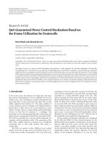
3.2.2. Modular Software Architecture. To ensure good exten-
sibility, a significant effort has been invested in object-
oriented software modeling. This section illustrates our
6 EURASIP Journal on Wireless Communications and Networking
MacSlotInfo
MacSlot
MacFrame
SlotsTable
NeighboursTable
FindFreeSlots
TdmaSlotsAllocator
findFreeSlots()
SlotsCommand
SlotsAllocator
slotsList
frameList
slotsCommandType()
processSlotsRequets()
state
idEmitter
idReceiver
macSlotInfo
nbSlots
idEmitter
idReceiver
allocators
allocateSlots()
slotsAllocationManager
commands
aemManager
framesAllocationManager
slotsTable
neighboursTable
findFreeSlots
chooseFreeSlots()
allocatorType()
priority
queuingTime
TdmaSlotsCommand
MacLayerEngine
SlotsAllocationManager
/
∗
The SlotsCommand list must be sorted from the highest priority
command to the lowest priority one
∗
/
list<SlotsCommand
∗
>::iterator it;
for (it
= commands→begin(); it != commands→end(); it++){
slotsAllocationManager
→allocateSlots(
∗
it);
}
}
/
∗
calls the SlotAllocators to allocate slots as requested by the
SlotCommand parameter
∗
/
list<SlotsAllocator
∗
>::iterator it;
list<MacSlot
∗
>
∗
slotsList;
for (it
= allocators→begin(); it != allocators→end(); it++) {
if (allocator
→allocatorType == command→slotCommandType()) {
slotsList
= allocator→fressSlotsAllocator→findFreeSlots(command);
allocator
→chooseFreeSlots(command, slotsList);
break;
}
}
Figure 4: Resource allocation class diagram.
approach by first presenting the design of the resource
allocation function. In this work, this function is run
by privileged nodes that manage resource allocation on
behalf of all nodes in their one-hop neighborhood. These
nodes receive radio resource requests from their neighbors,
determine which requests will be satisfied, and then send
back a response to their neighbors.
Figure 4 presents, as example, the UML class diagram of
the SlotsAllocator class. Filled in white are object classes that
compose the core software on which the resource allocation
source code is based. Filled in grey are object classes derived
from class of the core software that are related to a specific
radio resource allocation scheme. In the Time Division
Multiple Access (TDMA) scheme, radio resources are time
slots (MacSlot objects) that follow each other on the time
axis, organized in a MAC frame (MacFrame object). Input
informations to a slot allocator are radio resource requests.
Objects derived from SlotsCommand are associated to each
such request, and a slots allocator determines among these
requests which ones will be and not be satisfied.
The MAC layer manages a list of allocators, associating
each allocator to each resource request depending on the type
EURASIP Journal on Wireless Communications and Networking 7
FreeSpacePathLoss
InterfererNoiseInfo
NoiseInfo ReceiverNoise
RcmModule
FastFading
FastFadingInfo
RadioChannelManager
SlowFading
SlowFadingInfo
GroundBasedShadowing
UwbInterfererNoise
PathLoss
PathLossInfo
double x1, y1, x2, y2;
double getPathLoss(PathLossInfo
∗
pli);
variance
double getPathLoss(PathLossInfo
∗
pli) { return 1; }
list<double>
∗
interfererPower;
double getNoise(NoiseInfo
∗
ni);
double getNoise() {return 0; }
double getNoise(NoiseInfo
∗
ni) {return 0; }
RadioChannelManager
∗
rcm;
double getFastFading() { return 1; }
double getFastFading(FastFadingInfo
∗
ffi) { return 1; }
double getSlowFading() { return 1; }
double getSlowFading(SlowFadingInfo
∗
sfi) { return 1; }
PathLoss
∗
pl;
ReceiverNoise
∗
rn;
FastFading
∗
ff;
SlowFading
∗
sf;
Figure 5: Radio channel manager class diagram.
of the command. For TDMA access, TdmaSlotsCommand
is associated to a TdmaSlotsAllocator allocator. The benefit
of this approach is to allow an easy extension of what
currently exists: to add Orthogonal Frequency Division
Multiple Access (OFDMA) [26] radio access, a new OFDMA
allocator would have to be defined, associated with a new
OFDMA command.
Figure 5 presents the UML class diagram of the wire-
less channel model. A single RadioChannelManager object
shared between all network nodes has pointers to objects
that calculate the contribution of the four main parts of the
radio channel: fast and slow fading, path loss, and additive
noise. In the RISC project, specific code was written to
model the noise from multiuser interference on a CDMA
UWB channel [22](UwbIntefererNoise class derived from
the generic ReceiverNoise class) as well as ground based
shadowing (GroundBasedShadowing class derived from the
generic SlowFading class). To make use of these two models,
the only source code modification is to create the appropriate
objects when initializing the RadioChannelManager.The
choice of different channel effects is made through the
selection of the appropriate models, as in a toolbox.
3.3. Message Transmission in the Radio Access. Beyond pro-
tocol and software architecture described in the previous
sections, we describe in Figure 6 the sequence diagram
of the transmission at the lower part of the radio access
layer, from MAC to the radio channel. In phase 1, the
MAC sublayer sends the different MAC-PDU to its lower
Packing/Unpacking Manager layer (PUM). Then, from phase
8 EURASIP Journal on Wireless Communications and Networking
BeaconMessage
HelloMessage
AllocationRequestMessage
SlotControlMsg
→ Slot →
MAC
PUM
SlotControlMsg
→···
Modem
FEC
Ampli
TSM
Radio Rx
SlotControlMsg
→ Slot →···
RadioMsgBB [ComplexSignal]→···−{ChannelControlInfo}
BytesMsg
−{Layer2ControlInfo}
BytesMsg
−{Layer2ControlInfo}
BytesMsg
DL
PDU REQ
Data link
layer
Physical
layer
Radio
channel
1
5
6
7
8
3
2
4
9
Figure 6: Radio access sequence diagram at transmission side.
2 to phase 5 the MAC layer transmits a clock signal to
the physical layer, triggering a request for data to the PUM
entity and the transmission to the physical layer of a DL-
PDU using the format illustrated in Figure 3. The FEC then
adds error correcting bits (phase 6); the Modem modulates
bits into complex symbols (phase 7) that are forwarded
over the radio channel through the Ampli (phases 8 and 9)
using a RadioMsgBB message sent to all nodes that might
be concerned. Phase 2 covers more than one clock signal.
Indeed, in some cases it is necessary to transmit information
which is not supposed to be corrupted by the radio channel.
This is still possible in our simulation architecture: this
information is forwarded as a usual C++ object with the
RadioMsgBB message.
3.4. Introducing a Real Application Case: Video Live Transmis-
sion. The emulation of higher layers operation is illustrated
in this section. Typically, considering the case of video
transmission, as can be done in a client/server architecture,
real systems use the Real-Time Streaming Protocol (RTSP)
[27] which controls the delivery of data with real-time
properties. In particular this protocol allows the client and
server to negotiate the data request and the transmission
conditions and to choose the delivery channel (e.g., UDP,
TCP, multicast or unicast, etc.). As shown in Figure 7,in
our system, we are launching the session with the client
making a request for a given file (identified by its key) to the
server, which then answers favorably if it has the content at
its disposal. The session itself can then begin, with the start
request containing the setup elements, the converse reply and
acknowledgment messages. Once the session is established,
data can be transmitted. When the transmission conditions
are too degraded and no data is received, a new start request
Client
decoder session
Server
session encoder
Key (video) request
Key response
RTSP start REQ
RTSP start REP
RTSP start ACK
Data
RTSP ACK
Data
RTSP start REQ
RTSP start REQ
Start
RTSP start
ACK
Figure 7: Video session establishment sequence diagram.
can then be sent, which could be routed along a new (better)
path to resume the transmission.
4. Simulation Examples
In this section we present several results that have been
obtained with the proposed simulation framework and for
which both HFS and bit-level modeling were necessary.
EURASIP Journal on Wireless Communications and Networking 9
4.1. Data Link HARQ-Cross-Layer Scheme. Usually, hybrid
ARQ is integrated in the physical layer (e.g., WiMAX) for
practical implementation reasons. Moving it to the data link
layer allows to investigate cross-layer schemes such as the
one introduced in [28] for ARQ when the IP packets are
fragmented into N fragments to fit the MAC PDU size. In
this cross-layer strategy, the retransmission mechanism at the
data link layer exploits information from both the PHY layer
and the IP layer. When HARQ is used with soft information
in combination with such a cross-layer scheme [29, 30],
the HFS is needed. The cross-layer approach considers a
global persistence C for the set of fragments (MAC PDU)
coming from the same IP packet, whereas the conventional
one considers a per fragment persistence P , ignoring the fact
that it comes form a fragmented IP packet. The cross-layer
scheme will be referred as SDU-Based Strategy (SBS) and the
conventional one to as PDU-Based Strategy (PBS).
We have implemented both PBS and SBS in the sim-
ulation framework. This enables to assess the performance
of the different approaches using UDP trafficatdifferent
layers. Moreover, due to framework structure, once it is
implemented for one node, it is easy to simulate multi-
hop networks. Figure 8 illustrates the simulation results of
a UDP flow transmission using a TDMA access for one-
hop and two-hop networks. The simulation parameters are
N
= 3 fragments per IP packet, P = 8, and C = 24, which
ensure a fair comparison since for both strategies the same
maximum of retransmission credit per IP packet is allowed.
The simulation shows that
(i) the SBS outperforms the PBS and confirms the work
in [29],
(ii) the PER is larger at the IP layer than at data link layer,
which is due to the IP packet fragmentation effect,
(iii) the one-hop transmission performs better than the
two-hop one as expected.
4.2. Data Link HARQ-TCP Interactions. A tight integra-
tion with the resource allocation scheme is necessary to
provide the reverse way needed for the acknowledgment
transmission. This leads to nonnegligible delays between the
data transmission and the reception of the corresponding
acknowledgment. To cope with this delay we have introduced
a sliding window. Figure 9 represents the variations of
both the HARQ sender window and the TCP congestion
window during a 1 Mbytes file transfer (with no loss on the
wireless channel). The former opens and closes according
to the radio resources allocated to the TCP flow. Note
that between time of 1.3 seconds and 5.3 seconds TCP
does not allow the transmission of any data, implying a
minimum HARQ sender window. After time of 5.3 seconds,
the permanent state is reached, and alternating congestion
avoidance, fast retransmit, and fast recovery TCP phases
happen periodically, along with wide fluctuations of HARQ
sender window.
Figure 10 details what happens at the HARQ sender
window level. Wide variations are visible, due to interactions
between the TCP congestion control, the HARQ sliding
window, and the resource allocation mechanisms.
PER
10
−4
10
−3
10
−2
10
−1
10
0
SNR (dB)
−4 −3.5 −3 −2.5
PBS-IP 2-hop
PBS-IP 1-hop
PBS-MAC 1-hop
SBS-IP 2-hop
SBS-IP 1-hop
SBS-MAC 1-hop
Figure 8: PBS and SBS performance comparison with IR-HARQ,
for N
= 3, P = 8, and C = 24.
Window size
0
5
10
15
20
25
30
35
40
45
50
55
Time (s)
12345678910
HARQ window
TCP windows (scaled)
Figure 9: Joint evolution of the HARQ sender window and TCP
congestion window during ad hoc transmission.
Table 1: HARQ sliding window versus TCP throughput.
HARQ maximum window (#PDU) 31 16 8
Normalized TCP throughput 0,942 0,913 0,482
Note in Figure 10 that the HARQ window periodically
attains its maximum value, 31. In those cases, no more data is
transmitted over the wireless channel until acknowledgments
have been received, closing the window. When the maximum
value is not large enough, this entails a reduction in the TCP
throughput, as shown in Ta ble 1.
10 EURASIP Journal on Wireless Communications and Networking
Window size
0
5
10
15
20
25
30
35
40
45
50
Time (s)
66.26.46.66.87
HARQ window
TCP windows (scaled)
Figure 10: Zoom of Figure 9.
4.3. Video Transmission. The usage of HFS from and up to
the application level is justified in several cases by the interest
and necessity of representing true bit reality. One of these
cases corresponds to the introduction of forward error cor-
rection codes in the higher layers of the protocol stack, as for
instance, with RTP-FEC or more generally IETF FecFrame
approaches, which aim at overcoming remaining losses or
errors at transport or application layers, without requiring
a full TCP integrity mechanism. Another case corresponds
to the transmission of multimedia data, whose codecs are
often resilient to small errors or losses, and for which errors
or losses positions are critical to evaluate their real impact
on the end-user and measure the PQoS. This is the case
considered by the French ANR DITEMOI project, in which
error and loss resilient H.264/AVC decoders were introduced
[31], and new strategies for limiting retransmission in video
sessions in a multiple users context are being studied.
Figures 11 and 12 illustrate the type of results that can
be obtained for a video data transmission in the context of a
peer-to-peer communication with two interested users. Since
the simulator transmits the real bits of an input video, the
video can be reconstructed at the receiver side image after
image. Comparing the original video with the received one,
the Picture Signal to Noise Ratio (PSNR), which is a classical
objective measure of the video quality, can be computed.
Figure 11 reports for one user the variation of the PSNR as
a function of the frame number of the video sequence in two
cases: the first one corresponding to a reference case (solid
line) and the second one corresponding to an optimized
design (dashed line) where proxies are introduced and allow
fine treatments of imperfect packets. Moreover, for a given
frame number, the received images in the reference and
optimized cases are placed side by side in Figure 12, showing
that the simulator allows not only an objective measurement
but also a subjective evaluation of the video quality. The
frame, number 145, associated to the pictures in Figure 12
is identified by a vertical dotted line in Figure 11.
PSNR (dB)
5
10
15
20
25
30
35
40
45
Frame number
50 100 150 200 250 300
Reference
Optimized
Figure 11: PSNR comparison versus frame number between
reference and optimized processings.
(a)
(b)
Figure 12: Comparison of two video sequences quality at frame
number 145: (a) reference and (b) optimized.
EURASIP Journal on Wireless Communications and Networking 11
5. Conclusions
In this paper we presented the main features of a new
simulation framework using OMNeT++ for the study of
transmission of data and multimedia content over hybrid
wired/wireless ad hoc networks and the design of innovative
radio access schemes. Details of the API allowing high-
fidelity simulations by transmitting bits and bytes over the
radio channel have been provided along with simulation
results examples in the context of video and TCP/HARQ
schemes transmissions. This framework structure is devel-
oped in a flexible manner and can encompass various other
schemes such as multiple access, OFDMA, or cooperative
relaying communication techniques. Moreover, this flexi-
bility brought by the modular conception also allows to
capitalize on the previous developments by incremental
update of the simulation framework and makes it sustain-
able in time. As future work we plan to compare results
obtained through HFS as described in this paper with results
coming from less detailed simulations that do not take into
account the real bits of the trafficflowstransferredon
the network.
Acknowledgment
This work was partially supported by the French Agence
Nationale de la Recherche through projects DITEMOI
(ANR-06-TCOM-003) and RISC (ANR-06-TCOM-015).
References
[1] “IEEE Std 802.16e-2005 and IEEE Std 802.16-2004/Cor 1-
2005 IEEE Standard for Local and metropolitan area networks:
Part 16: Air Interface for Fixed Broadband Access Systems;
Amendment 2: Physical and Medium Access Control Layers
for Combined Fixed and Mobile Operation in Licensed Bands
and Corrigendum 1,” February 2005.
[2] J. Schiller, Mobile Communications, Addison-Wesley, Reading,
Mass, USA, 2003.
[3] “Mobility framework (MF) for simulating wireless and mobile
networks using OMNeT++,” rceforge
.net/.
[4] A. Kopke, et al., “Simulating wireless and mobile networks in
omnet++ the mixim vision,” SIMUTools, March 2008.
[5]J.Huusko,J.Vehkaper
¨
a, P. Amon, et al., “Cross-layer archi-
tecture for scalable video transmission in wireless network,”
Signal Processing: Image Communication,vol.22,no.3,pp.
317–330, 2007.
[6] W. T. Kasch, J. R. Ward, and J. Andrusenko, “Wireless network
modeling and simulation tools for designers and developers,”
IEEE Communications Magazine, vol. 47, no. 3, pp. 120–127,
2009.
[7] “Yet Another Network Simulator, Institut National de
Recherche en informatique et automatique (INRIA),” October
2006, />[8] A. Varga, “OMNeT++ Discrete Event Simulation System,”
/>[9] DITEMOI project, />DITEMOI.
[10] RISC project, />[11] OPNET Technologies, Inc., />[12] “The Network Simulator—ns-2,” Information Sciences Insti-
tute. The University of Southern California, July 2006, http://
www.isi.edu/nsnam/ns.
[13] A. Kuntz, et al., “Introducing probabilistic radio propagation
models in omnet++ mobility framework and cross validation
check with ns-2,” SIMUTools, March 2008.
[14] “INET framework (MF) for communication networks
simulation for the OMNeT++ environment,” http://inet
.omnetpp.org/.
[15] S. Lin, D. J. Costello Jr., and M. J. Miller, “Automatic-
repeat-request error control schemes,” IEEE Communications
Magazine, vol. 22, no. 12, pp. 5–17, 1984.
[16] T. Wiegand, G. J. Sullivan, G. Bjontegaard, and A. Luthra,
“Overview of the H.264/AVC video coding standard,” IEEE
Transactions on Circuits and Systems for Video Technology, vol.
13, no. 7, pp. 560–576, 2003.
[17] H. Schwarz, D. Marpe, and T. Wiegand, “Overview of the
scalable video coding extension of the H.264/AVC standard,”
IEEE Transactions on Circuits and Systems for Video Technology,
vol. 17, no. 9, pp. 1103–1120, 2007.
[18] W. Yuan, G. Zhu, and G. Liu, “Cross-layer schemes for opti-
mization of VoIP over 802.11e WLAN,” in Proceedings of IEEE
Global Telecommunications Conference (GLOBECOM ’07),pp.
4883–4887, Washington, DC, USA, November 2007.
[19] J. Mitola III and G. Q. Maguire Jr., “Cognitive radio: making
software radios more personal,” IEEE Personal Communica-
tions, vol. 6, no. 4, pp. 13–18, 1999.
[20] N. Baldo, et al., “ns2-miracle: a modular framework for multi-
technology and cross-layer support in network simulator
2,” in Proceedings of the International Workshop on Network
Simulation Tools (NSTools ’07), Nantes, France, October 2007.
[21] P. Duhamel and M. Kieffer, Joint Source-Channel Decoding—A
Crosslayer Perspective with Applications in Video Broadcasting,
Academic Press, New York, NY, USA, 2009.
[22] F. Kharrat-Kammoun, P. Ciblat, and C. J. Le Martret, “Error
probability approximation and codes selection in presence of
multi-user interference for IR-UWB,” in Proceedings of IEEE
International Symposium on Personal, Indoor and Mobile Radio
Communications (PIMRC ’08), Cannes, France, September
2008.
[23] G. Booch, Object-Oriented Analysis and Design with Applica-
tions, Addison-Wesley, Menlo Park, Calif, USA, 1994.
[24] E. Gamma, R. Helm, R. Johnson, and J. Vlissides, Design Pat-
terns: Elements of Reusable Object-Oriented Software, Addison-
Wesley, Reading, Mass, USA, 1995.
[25] A. Sendonaris, E. Erkip, and B. Aazhang, “User cooperation
diversity—part I: system description,” IEEE Transactions on
Communications, vol. 51, no. 11, pp. 1927–1938, 2003.
[26] G. Parsaee and A. Yarali, “OFDMA for the 4th generation
cellular networks,” in Proceedings of the Canadian Conference
on Electrical and Computer Engineering, vol. 4, pp. 2325–2330,
2004.
[27] “Real Time Streaming Protocol (RTSP),” IETF RFC 2326,
April 1998 />[28] Y. Choi, S. Choi, and S. Yoon, “MSDU-based ARQ scheme for
IP-level performance maximization,” in Proceedings of IEEE
Global Telecommunications Conference (GLOBECOM ’05), vol.
5, pp. 2495–2499, St. Louis, Mo, USA, November 2005.
[29] A.LeDuc,C.J.LeMartret,andP.Ciblat,“Packeterrorrate
and efficiency closed-form expressions for cross-layer hybrid
ARQ schemes,” in Proceedings of IEEE Workshop on Signal
Processing Advances in Wireless Communications (SPAWC ’09),
pp. 379–383, Perugia, Italy, June 2009.
12 EURASIP Journal on Wireless Communications and Networking
[30] A. Le Duc, C. J. Le Martret, and P. Ciblat, “Delay and jitter
closed-form expressions for cross-layer hybrid ARQ schemes,”
in Proceedings of the 70th IEEE Vehicular Technology Conference
(VTC ’09), Anchorage, Alaska, USA, September 2009.
[31] C. Lamy-Bergot, B. Candillon, B. Pesquet-Popescu, and B.
Gadat, “A simple multiple description coding scheme for
improved peer-to-peer video distribution over mobile links,”
in Proceedings of IEEE Picture Coding Symposium (PCS ’09),
pp. 1–4, Chicago, Ill, USA, April 2009.