Báo cáo hóa học: "Research Article WING/WORLD: An Open Experimental Toolkit for the Design and Deployment of IEEE " ppt
Bạn đang xem bản rút gọn của tài liệu. Xem và tải ngay bản đầy đủ của tài liệu tại đây (1.71 MB, 17 trang )
Hindawi Publishing Corporation
EURASIP Journal on Wireless Communications and Networking
Volume 2010, Article ID 730198, 17 pages
doi:10.1155/2010/730198
Research Article
WING/WORLD: An Open Experimental Toolkit for
the Design and Deployment of IEEE 802.11-Based Wireless
Mesh Networks Testbeds
Fabrizio Granelli,
1
Roberto Riggio,
2
Tinku Rasheed,
2
and Daniele Miorandi
2
1
DISI—University of Trento, Via Sommarive 14, 38123 Trento, Italy
2
CREATE-NET, Via Alla Cascata 56/C, 38123 Trento, Italy
Correspondence should be addressed to Fabrizio Granelli,
Received 8 June 2009; Revised 7 October 2009; Accepted 25 November 2009
Academic Editor: Christian Ibars
Copyright © 2010 Fabrizio Granelli et al. This is an open access article distributed under the Creative Commons Attribution
License, which permits unrestricted use, distribution, and reproduction in any medium, provided the original work is properly
cited.
Wireless Mesh Networks represent an interesting instance of light-infrastructure wireless networks. Due to their flexibility and
resiliency to network failures, wireless mesh networks are particularly suitable for incremental and rapid deployments of wireless
access networks in both metropolitan and rural areas. This paper illustrates the design and development of an open toolkit
aimed at supporting the design of different solutions for wireless mesh networking by enabling real evaluation, validation, and
demonstration. The resulting testbed is based on off-the-shelf hardware components and open-source software and is focused
on IEEE 802.11 commodity devices. The software toolkit is based on an “open” philosophy and aims at providing the scientific
community with a tool for effective and reproducible performance analysis of WMNs. The paper describes the architecture of the
toolkit, and its core functionalities, as well as its potential evolutions.
1. Introduction
Wireless Mesh Networks (WMN) [1, 2]representatechno-
logical bridge between mobile ad hoc networks (MANETs)
and traditional infrastructure networks, such as the ones
based on the IEEE 802.11 family of standards. Compared
to infrastructure networks, WMN offer several advantages:
(i) they allow the combination of different wireless tech-
nologies, such as cellular, WiFi, and WiMAX; (ii) they can
be incrementally deployed, in order to gradually extend
connectivity and capacity, avoiding massive investments.
Unlike the MANET scenario, where all nodes act as both
host and routers, in a WMN a distinction exists in terms of
functionalities between traffic source/termination points and
pure relay devices.
A typical WMN consists of several nodes (routers
and gateways) which exploit multihopping in order to
build and maintain a wireless backhaul. WMNs enhance
traditional star-shaped network architectures by provid-
ing increased robustness (e.g., no single points of failure
are present and broken/congested links are encompassed),
scalability and flexibility (without the need for deploying
cables, connectivity may be provided only where and when
needed/economically attractive), and incremental deploy-
ment. Moreover, WMNs can support heterogeneous trans-
mission technologies.
Mesh routers are typically characterized by a small
physical footprint which makes them suitable for a wide
range of deployments. As for example, due to their low-
energy requirements, mesh routers can be deployed as
completely autonomous units with solar, wind, or hydro
power. Moreover, WMNs are the perfect enabling technology
for community networks, in that their distributed nature
lends itself to a decentralized ownership model where each
participant owns and maintains his/hers own hardware.
Finally, WMNs are also expected to lower the entrance
barrier for network operators by allowing them to deploy a
wireless backhaul in an incremental fashion.
Albeit, several commercial WMNs are already available
[3–7], even at (relatively) low prices, no specific study on
2 EURASIP Journal on Wireless Communications and Networking
the design principles to be followed in order to fully exploit
the features of the wireless mesh networking paradigm has
been published yet. As a matter of fact, most available works
on performance evaluation of WMNs are based on simu-
lation studies, or, in some cases, on analytical frameworks.
However, given the complexity and the heterogeneity of
the wireless mesh networking scenario and given the high
number of functionalities involved—crossing several layers
of the protocol stack—it emerges a clear need for real-world
deployments and prototypes where novel methodologies
and algorithms can be tested and evaluated in an isolated
environment.
In this work, an “open” approach is used to design
and deploy a wireless mesh networking toolkit where off-
the-shelf and low-cost hardware components are used as
building core components. As a case study, we discuss
the WING/WORLD testbed developed and deployed using
the aforementioned toolkit. All the developed software is
released under a BSD License [8, 9] and is made freely
available to the research community to expand and modify it
beyond its current functionalities. The reference technology
is IEEE 802.11, but the toolkit can be extended to easily incor-
porate other wireless (e.g., WiMAX) and wired technologies.
The rest of the paper is organized as follows. Section 2
discusses the most relevant trade-offs that we faced in
designing the WING/WORLD toolkit. Section 3 describes
the system’s concept and architecture. Additional technical
details on the features currently supported by the toolkit are
given in Section 4, while a comparison with other academic
testbedsandprototypesisprovidedinSection 5. Use cases
are presented and discussed in Section 6. Finally, Section 7
draws the conclusions pointing out current and future
research directions.
2. Platform Design Choices and Trade-offs
In order to deliver a viable technological solution for
ubiquitous wireless network access, WMNs are required to
support a broad range of benchmarks and services. Given
such a background, testbeds represent the ideal play-ground
where innovative solutions can be analyzed in a controlled
and realistic environment. As a result, the design of a wireless
mesh networking toolkit must be driven by both current
research trends and the requirements imposed by the target
deployment scenario. This section aims at discussing the
most relevant trade-offs that we faced in designing the
WING/WORLD platform. We invite the reader to consider
the discussed issues not as “closed” topics but instead as
starting ground for further investigations.
2.1. Hardware Platforms. In designing a WMN, several
issues, ranging from platform selection and node deploy-
ment to the selection of a suitable software framework for
an efficient and useful testbed operation, must be carefully
considered by the network engineer. It is worth noting that
none of the aforementioned choices should be considered as
the only driving factor in the testbed development. Instead,
as we will see in the following sections, they all must be
addressed as a coherent solution to a multitude of problems.
The choices to be made during the platform selection
phase heavily depend on research directions and reference
application scenarios in terms of network type and size,
expected users, and budget.
Being characterized by costs between 80–100C
(at the
time of this writing), home wireless routers (e.g., the
Linksys WRT54G) deliver the cheapest solution for wireless
mesh networking. The major drawbacks of these devices
are the modest processing power, due to CPUs designed
for lightweight loads, and the limited radio capabilities,
due to small antennas and low power WiFi cards. On the
other hand, embedded platforms provide high flexibility in
terms of custom and off-the-shelf hardware components and
are characterized by a wide performance range. Moreover,
outdoor deployment is made easier by tailored water-proof
enclosure, Power-Over-Ethernet support, and the absence
of any moving part. Embedded platforms based on the
x86 architecture (e.g., PCEngines, Soekris, etc.) do not
require cross compilation and standard development tools
and OSes can be used, while platforms based on non-x86
CPUs (e.g., Gateworks, Routerboard, etc.) provide a better
price/performance ratio with the drawback of requiring cross
compilation.
It is worth noting that processing power and storage
space are hard constraints to both the services and the
experiments that can be supported by the network. As a
matter of fact, multiradio configurations can easily exceed
the CPU capabilities of many embedded platforms especially
if traffic forwarding is coupled with synthetic traffic genera-
tion.Moreover,asuitablestoragespacemustbeprovidedin
order to collect measured data.
2.2. Software Platforms. A wide range of OSes is available
for the aforementioned hardware platform, ranging from
open-source systems like all Linux variants and
∗
BSD to
commercial real-time solutions. Since no currently available
software platform may be considered as the final solution
for wireless mesh networking, an open-source OS, which
makes available the source code under terms that allow mod-
ification and redistribution, is therefore the optimal choice
to speed up research and prototyping. Linux-based OSes
are available for the most important embedded platforms.
However, it is worth noting that, albeit these OSes may be
very similar to the Linux distributions available on common
PCs, the available software packages and the userspace tools
and utilities may differ significantly due to both CPU-specific
requirements and system resources constraints.
2.3. Routing Frameworks. There are three primary compo-
nents that influence the routing framework: (i) the protocol
architecture, (ii) the routing scheme, and (iii) the software
implementation. Routing can be either provided at level
three of the ISO/OSI networking stack as modification of
the standard IP protocol or by adding an interposition layer
between the Data Link Layer and the Network layer. In the
latter solution (usually referred to as Layer 2.5 routing), the
multihop backhaul is transparent to the upper networking
EURASIP Journal on Wireless Communications and Networking 3
stack, making the WMN appears just as another Ethernet
link. On the other hand, such an approach introduces
additional encapsulation and processing overhead as a result
of, respectively, the header and checksum required by the
interposition level. This implies a slight degradation in over-
all performance, in terms of both throughput and latency.
Due to the large availability of routing protocols originating
from the MANETs research, Layer 3 routing has been the
most popular solution in the earlier WMN implementations.
Solutions based on Layer 2.5 routing started mushrooming
soon after in both academic and private research institutes
(MIT Roofnet and Microsoft MCL are the two most notable
precursors). Nowadays, we are observing an increasing trend
from commercial vendors toward Layer 2 routing. Such
an approach is however typically based on proprietary
hardware/software solutions. The authors advocate for Layer
2.5 due to both its enhanced scalability and network stack
transparentness.
WMNs share a number of features with ad hoc net-
works [10]. In particular, WMNs are characterized by
self-organization and self-healing capabilities and exploit
multihopping to build a wireless backhaul for delivering
Internet connectivity to end-users. As a result, many routing
protocols developed for Mobile Ad hoc Networks (MANETs)
have been adapted to fit the mesh environments. However,
as opposed to the MANETs paradigm, research efforts in
the WMN community focused on network scalability rather
than mobility. As a result, particular attention has been
devoted by the academic community to the introduction of
novel routing metrics capable of taking into account wireless
channel characteristics [11] and to multiradio/multichannel
architecture capable of increasing the overall network capac-
ity [12].
Parallels activities aim at addressing the WMNs scala-
bility issues by employing frequency agile/cognitive radios,
dynamic spectrum access, and clustering algorithms. In [13]
the authors propose the COMNET framework. COMNET
exploits intelligent frequency-shifting self-managed mesh
network in order to implement dynamic spectrum sensing
and management techniques allowing radios to use frequen-
cies other then those located in the ISM bands. Additionally,
in [14] a novel cluster-based middle-ware is proposed.
The proposed solution significantly reduces the bandwidth
use within the wireless mesh backbone by introducing a
clustering service and an adapter. The former builds and
maintains clusters of nodes; the latter acts as interface
with the applications. However, all these advanced wireless
radio technologies and architectures require a revolutionary
approach to the communication protocols’ design in order to
reduce congestion, eliminate potential bottlenecks links, and
eventually facilitate the commercialization of WMNs.
Routing protocols are typically generally classified as
proactive, reactive,andhybrid. Proactive protocols maintain
a list of all destinations and routes while reactive protocols
discover routes on-demand when a packet needs to be
forwarded. Such a behavior makes proactive routing less
suitable for WMNs or in general for networks characterized
by low-churn rates (number of nodes that leave the network
during a specified time period divided by the average total
number of nodes over that same time period). It is the
authors’ standpoint that on-demand route discovery can
result in much less traffic than the standard proactive
approach, especially when innovative route caching schemes
are employed.
Several proactive and reactive routing protocols are
already available for deployment over a WMN. Their imple-
mentations differ by code maturity, license, and degree of
modification to the standard networking stack. In such a
context, moving the routing logic from kernel-space into
user-space libraries offersconsiderableadvantagesinterms
of both faster development cycle and easier debugging
at the expense of performance reduction. Due to such
considerations, many academic research prototypes exploit
routing protocol implementations running in the user-space.
3. Concept and System Architecture
The WING/WORLD testbed is an experimental IEEE 802.11
wireless mesh network built using off-the-shelf components.
Specific attention is aimed at providing a solution that
researchers around the world can easily replicate at their
premises and possibly connect to the existing infrastructure
to enable to enlarge the test-site. It is worth mentioning
that all the developed software has been released under a
BSD License and is made fully available to the research
community [8, 9].
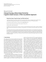
Current configuration is based on 23 nodes deployed
across two buildings, implementing two local indoor wireless
mesh networks interconnected by an outdoor WiFi point-
to-multipoint wireless link. The geographical distribution
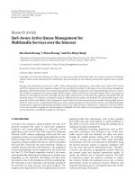
of the testbed is presented in Figure 1. The system design
was driven by our previous work on the state-of-the-art
solutions for engineering a WMN testbed [15] by applying
the observed guidelines to a real-world scenario, namely, the
WING/WORLD testbed.
3.1. Hardware Platform. Mesh routers are built exploiting
three different types of processor boards, namely, the
PCEngines ALIX 2C2 (500 MHz x86 CPU, 256 MB of RAM)
processor board, the PCEngines WRAP 1E (233 MHz x86
CPU, 128 MB of RAM) processor board, and the Gateworks
Cambria GW2358-4 (667 MHz ARM CPU, 128 MB of
RAM). Operating system and application are stored on a
1 GB Compact Flash card for the PCEngines platforms and
on the 32 MB embedded flash memory for the Gateworks
platform (in this case a 4 GB Compact Flash is used to
provide additional storage). It is worth noting that the
full WING/WORLD firmware including development and
testing tools (traffic generator, loggers, etc.) requires about
16 MB of storage space. A stripped down version of the
firmware without development and testing tools requires less
than 4 MB of storage.
Connectivity is provided by 2 Ethernet channels, 2/4
miniPCI slots, (PCEngines/Gateworks) and one serial port.
PCEngines ALIX/WRAP boards are equipped with two
Mikrotik R52 WiFi IEEE 802.11a/b/g cards based on the
Atheros AR2412 chipset. Gateworks boards are equipped
4 EURASIP Journal on Wireless Communications and Networking
Figure 1: WING/WORLD testbed geographical distribution.
with two Ubiquiti SR71-A WiFi IEEE 802.11a/b/g/n cards
based on the Atheros AR9160 chipset. On the PCEngines
platform, one interface builds and maintains the multihop
wireless backhaul, while the other interface can be configured
eitherinClientorinMastermode.Theformerconfiguration
allows the node to share an already available WiFi connection
with the entire WMN while the latter configuration is
used to provide a standard IEEE 802.11 Access Point.
Single interface setups are also supported; however, in
this case the device acts as a pure relay node. Dual and
single NIC nodes can coexist in the same network. On
the Gateworks platform, both interfaces are used to build
and maintain the multihop wireless backhaul implementing
a true multiradio/multichannel WMN exploiting dynamic
channel assignment. An additional WiFi interface can also
be used to provide Internet connectivity to the network.
Finally, platforms with USB support (PC Engines ALIX and
Gateworks Cambria) can be equipped with a cellular modem
allowing the entire WMN to exploit a UMTS/GPRS network
as a gateway link to the Internet.
Being based on the x86 architecture, the PCEngines
boards (similar systems are provided by Soekris Engineering)
deliver high flexibility in terms of choice of components
while at the same time providing us with platform suitable
for real-world deployments in terms of both maintenance
costs and expected performances. Moreover, no cross com-
pilation is required and standard development tools and
OSes can be used. On the other hand, the Gateworks boards
deliver higher performances and support up to 4 miniPCI
wireless adapters enabling effective multiradio/multichannel
deployments.
The selection of the Wireless NIC to be deployed in
our testbed has been driven by the need to configure
and control as many low-level (physical) parameters as
possible. The selected Atheros-based Wireless NICs allow
to control parameters such as transmission bit-rate, carrier
sense thresholds from userspace and provide transmission
feedback for unicast frames which are not successfully
delivered. Moreover, raw 802.11 frames are exposed by the
driver, allowing to control most of the node’s functionality
at the application level; for example, it is possible to get
per-packet signal and noise readings and to send broadcast
frames at arbitrary rates.
3.2. Software Platform. OpenWRT [16] has been selected as
Operating system for our testbed. OpenWRT is a minimalist
BusyBox/Linux distribution released under a GPL license
[17]. It provides an automated system for downloading the
source code for both the kernel and the userspace tools, and
compiling it to work on any supported platform. Moreover,
it is characterized by a small memory and disk footprint
making it suitable for a wide rage of networking devices.
Finally, it provides hardware configuration and maintenance
abstraction through a custom system and package configura-
tion facility called UCI (Universal Configuration Interface)
and exploiting MIB-like structure in order to streamline
device management using SNMP [18].
EURASIP Journal on Wireless Communications and Networking 5
Network address translation
(NAT)
Aggregation buffer
Packet classifier
(DSCP-based)
Click modular router
Fair buffer
Fair buffer
Fair buffer
FIFO
User data
(TUN interface)
Gateway
discovery
Routing
Link probing
(WiFi)
WirelessWired
(ethernet)
Wireless
(UMTS)
Packet scheduler
Backhaul interfaces
Backhaul links
Wireless
NIC 1
Wireless
NIC 2
BE AF11 AF21 AF31 AF41
Figure 2: Architecture of the trafficdifferentiation scheme implemented in the WING/WORLD toolkit.
It is worth noting that, being based on the x86 archi-
tecture, the PCEngines processor boards do not require,
in principle, cross-compilation; however, we decided to
use OpenWRT in order to abstract from the underlying
hardware architecture making the WING/WORLD toolkit a
platform-agnostic solution for wireless mesh networking. As
a matter of fact, OpenWRT proved to be the most effec-
tive “glue” between heterogeneous hardware and software
requirements.
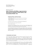
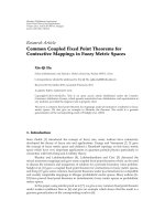
The overall software architecture is sketched in Figure 2.
As it can be seen from the picture, the node supports multiple
backhauling technologies (Wired, WiFi, and UMTS). The
software can seamlessly switch from one backhaul link the
the other. However, due to the use of Network Address
Translation (NAT) techniques at the mesh gateway, existing
connections exploiting stateful protocols, such as TCP, are
terminated when the backhaul link is switched. Likewise end-
users applications that rely on NAT traversal techniques in
order to implement client-to-client communications (e.g.,
peer-to-peer and VoIP) cannot survive the transition and
are bounded to drop their active connections. It is worth
underlying that, such a behavior derives from the joint use
of NAT and network masquerading (or IP masquerading).
This technique allows the network administrator to “hide”
an entire address space (typically private network addresses)
behind a single IP address (typically a public address). If on
one hand such a technique allowed to tackle the exhaustion
of IPv4 address space, on the other hand hosts behind NAT-
enabled routers do not have end-to-end connectivity, which
in time breaks the operations of stateless protocols such as
UDP or hinder the services that require the initiation of TCP
connections from the outside network.
The above mentioned issues are typically addressed
using a variety of NAT traversal protocols. NAT traversal
is a generic term used to identify techniques that establish
and maintain TCP and/or UDP connections across NAT
gateways. The general goal of a client implementing a NAT
traversal protocol is to know its own external address (i.e.,
the address behind which the local address space has be
hidden). The client can then start the communication by
advertising its external NAT address to its peers, rather than
the masqueraded (local) address that is not reachable for
its peers on the public network. However, NAT traversal
techniques are not designed to handle dynamic network
egress points, as a matter of fact, a client has no way of
notifying its peers that its external address has changed.
Possible solutions involve modifying currently used NAT
traversal protocols (e.g., Session Traversal Utilities for NAT
[19]) in order to support dynamic network egress points or
implementing a Mobile IP architecture in order to allow end-
users’ client to roam across different public networks. Both
approaches are highly invasive and as such are out of the
scope of this work.
Routing software is implemented using the Click mod-
ular router [20]. A Click router is built by assembling
several packet processing modules, called elements, forming
a directed graph. Each element is in charge of a spe-
cific function such as packet classification, queuing, and
interfacing with networking devices. Click comes with an
extensive library of elements supporting various types of
packet manipulations. Such a library enables easy router
configuration by simply choosing the elements used and
the connections among them. Finally, a router configuration
can be easily extended by writing new elements. The Click
modular router is available as both Linux Kernel Module and
user-space driver, allowing straightforward porting of a user-
space implementation to kernel-space. Mesh routers uses
the Click software router toolkit for route/gateway discovery,
packet forwarding, and to implement a DiffServ-like traffic
differentiation architecture. These features are sketched in
Sections 3.3 and 3.4, respectively, while details about the
modular gateway architecture (left hand block) and the
multiradio mesh backhaul (right hand block) are given in
Section 4.
3.3. Routing Framework. The WING/WORLD toolkit is built
on top of the Roofnet platform. Roofnet is an experimental
WMN developed by the MIT. The Roofnet architecture is
describedindetailin[21]. Roofnet routes packets using
6 EURASIP Journal on Wireless Communications and Networking
a DSR-like routing protocol called SRCR exploiting the
Estimated Transmission Time (ETT) as routing metric [22]
and optimized for network scalability and throughput rather
than for supporting mobility. The ETT metric aims at
estimating the amount of time required to transmit a packet
over a wireless link (including retransmission). The ETT
metric is computed as follows:
M
ETT
=
1
P
ACK
R
,
(1)
where R is an estimate of the highest effective throughput
achievable in the forward direction, and P
ACK
is the delivery
probability of the ACK signal in the reverse direction (d
rev
).
Since r
x
is the estimated throughput of broadcast packets in
the forward direction at the transmission rate of x Mb/s, the
parameter R can be computed as follows:
R
= max
(
r
1
, r
2
, r
5.5
, r
11
)
,
r
x
= d
fwd
x,
(2)
where d
fwd
is the link delivery probability in the forward
direction. In order to compute the forward (d
fwd
)andreverse
(d
rev
) link delivery ratios, each node periodically broadcasts
a sequence of five probes: one short probe aimed at modeling
the ACK transmission and one long probe for each available
transmission rate (broadcast frames are not acknowledged
nor retransmitted by IEEE 802.11 devices). Each node keeps
track of the number of probes received during an observation
window W.Atanytime,d
rev
is then given by.
d
rev
(
t
)
=
count
(
t −W, t
)
w/τ
.
(3)
Note that count (t
− W, t) is the number of probes
received during the observation window W,andw/τ is
the number of probes that should have been received.
Finally each probe sent by a node contains the number
of probes packets received by the same node from all its
neighbors during the last observation window. Such a design
choice allows the receiver to compute the forward delivery
ratio d
fwd
toward the node from which the probe was
originated. Using two probes to estimate data and ACK
delivery ratios separately allows the routing layer to properly
model asymmetric links and to cope with the hidden node
phenomena. In fact, probes lost at the receiver side due to
interference are taken into account during the computation
d
fwd
at the transmitting side by exploiting the information
piggy-backed into each probe.
The default Roofnet implementation has been extended
with additional modules responsible for QoS management.
These enhancements are described in detail in [23–25]. For
readers’ convenience, a brief overview of their main features
is provided in the next section.
3.4. QoS Extensions. The WING/WORLD toolkit imple-
ments a traffic prioritization scheme based on the Diff-
Serv [26] framework in order to allow classification and
differentiated treatment. Network traffic entering a mesh
Table 1: PHBs supported by the WING/WORD module for
Differentiated Services.
DSCP PHB Weights Queuing TrafficType
0Default1 ADRR Best Effort
0x0A AF11 2 ADRR Low Priority
0x12 AF21 4 ADRR Medium Priority
0x1A AF31 8 ADRR Streaming (UDP)
0x22 AF41 8 ADRR w/A-MSDU Real-time (UDP)
router is classified by DSCP code and then fed to a suitable
queue. Trafficdifferentiating is provided by means of a
Deficit Weighted Round Robin (DWRR) scheduler which
pulls packets from buffers, according to some input weights
(see Table 1 ).
Each buffer maintains a pool of queues and a hash
table that associates the MAC destination addresses with one
of those queues. Incoming MAC frames are first classified
according to their destination address and then fed to the
corresponding queue. If such a queue does not yet exist,
it is created dynamically by the scheduler. Unused queues
are moved from the hash table to the pool. This is done in
order to alleviate the need for repeated memory allocation
as neighbors come and go. Within each buffer, two different
link scheduling policies are supported by the system:
(i) Airtime Deficit Round Robin (ADRR).Itaimsat
providing intracell airtime fairness. ADRR enhances
the Deficit Round Robin (DRR) discipline by taking
into account the channel quality which in time
prevents a node affected by high-packet loss from
monopolizing the wireless channels thus lowering the
performance of the whole system.
(ii) ADRR with Frame Aggregation.Itaimsatreducing
the MAC service time by concatenating several MAC
Service Data Units (MSDUs) to form the data pay-
load of a large Aggregated-MSDU (A-MSDU). Such
packet aggregation scheme leverages the channel
probing functionalities of mesh routers in order to
compute the optimal saturation burst length.
4. Platform Details and Options
This section provides additional details on the features
currently supported by the WING/WORLD toolkit. The
system components illustrated in the following subsections
are the following:
(i) self-configuring backhaul,
(ii) multipleradio support,
(iii) opportunistic scheduling,
(iv) trafficaggregation,
(v) authentication.
EURASIP Journal on Wireless Communications and Networking 7
NoRoute
Relay
Cellular
StartRelaying StartGateway
StartGatewayStartGateway
WiredUp
WiFiUp
WiFiWired
WiFiUpWiredUp
PlugNode
Disconnect
NoneUp CellularUp
LostAssociation
LostAarrier WiredUp
WiredUp
Figure 3: State diagram for the gateway module. Events that cannot occur in a given state are not accounted.
However, given the modular nature of the platform,
it must be underlined that additional modifications or
extensions can be easily introduced. As a matter of fact,
each of the aforementioned components is independent from
the underlying routing layer and can be readily used in
conjunction with other routing protocols implementations
(i.e., OLSRd [27], BATMAN [28], etc.). For example, both
the authentication and the self-configuring backhaul are
implemented using standard tools available on any Unix-like
platform (GNU/Linux, all the children of BSD, etc.). Likewise
both the opportunistic scheduling and trafficaggregation
modules do not break the standard ISO/OSI (with the
exception of the cross-layer interfaces used to access link level
parameters; however, such interfaces can be easily adapted
to other link-aware routing protocol) layering allowing
straightforward porting to other platforms and routing
protocols.
4.1. Self-Configuring/Self-Healing Backhaul. The presence
of a backhaul technology represents one key differentia-
tion points between WMN and the traditional MANET
paradigm. The term backhaul is generally used [2] to identify
a technology in charge of forwarding the traffic from the
originator node to an external network (i.e., the Internet).
The WING/WORLD nodes can automatically detect if they
are relays or mesh gateways. A mesh node autoconfigures
itself as gateway if an IP address can be obtained using DHCP
over one of its backhaul links and if a list of well-known
Internet addresses can be reached. At the present moment,
three different backhaul technologies are supported.
(i) Wired. The first Ethernet interface available on the
node, typically the eth0 device.
(ii) Wireless (WiFi). In dual radio setups, the second WiFi
interface can be configured in Client mode allowing
the node to exploit an existing IEEE 802.11 AP as
backhaul link to the Internet.
(iii) Wireless (Cellular). If a cellular modem is available,
the mesh node can exploit an UMTS/GPRS network
as backhaul link to the Internet. The cellular modem
must be equipped with an SIM card holder (i.e.,
Huawei E169, Sierra 881, etc.) and an active SIM card
must be inserted.
In the current implementation, only one backhaul link
can be active at a given time; however, different mesh
gateways can exploit different backhauling technologies
providing the testbed with an increased resiliency to network
failures. It is worth noting that using more than one
backhauling technology at the same time would not increase
the network performances in that the typical bottleneck in
a WMN lies at the last hop toward the mesh gateway whose
capacity is at least an order of magnitude smaller than any of
the available backhauling technology (with the sole exception
of the UMTS backhaul which is to be considered anyway as a
backup solution).
The wired interface takes precedence over both wireless
technologies, while the WiFi backhaul takes precedence over
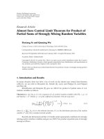
the cellular link. A Finite State Machine (FSM) has been
implemented in order to properly handle the backhaul’s
configuration without having either to reboot the node or
to disrupt the normal network operations (Figure 3). Each
backhaul technology is associated with a state. Additionally,
the FSM defines the following states.
8 EURASIP Journal on Wireless Communications and Networking
Table 2: State transition table. Events that cannot occur in a given state are not accounted.
Current state Event Action Next state
null PlugNode — NoRoute
NoRoute WiredUp Start Gateway Wired
NoRoute WiFiUp
∧¬WiredUp Start Gateway WiFi
NoRoute CellularUp
∧¬WiFiUp∧¬WiredUp Start Gateway Cellular
NoRoute NoneUp Star Relaying Relay
Wired LostCarrier Star Relaying Relay
WiFi WiredUp — Wired
WiFi LostAssociation Star Relaying Relay
UMTS WiredUp — Wired
UMTS WiFiUp — WiFi
UMTS Disconnect Star Relaying Relay
Relay WiredUp Start Gateway Wired
Relay WiFiUp
∧¬WiredUp Start Gateway Wireless
Relay CellularUp
∧¬WiFiUp∧¬WiredUp Start Gateway Cellular
Relay NoneUp — Relay
(i) Relay. None of the backhaul links are active. The node
configures itself as pure relay node. In dual-radio
setups, the node also act as IEEE 802.11 AP providing
the end-users with standard hotspot.
(ii) NoRoute. None of the backhaul links are active and
no multihop mesh backhaul could be configured. The
node configures itself as an IEEE 802.11 AP; however
no Internet connectivity is provided to the hotspot.
ThespecificationoftheFSMisprovidedinTa bl e 2
as State Transition Table (STT). The vertical dimension
indicates the current state; the horizontal dimension indi-
cates possible events; the row/column intersections contains
the next state if an event happens and the actions to be
performed when the state transition occurs. Please note that
PlugNode is an event that comes from the external world (i.e.,
powering up the mesh node). Here follows a description of
all the possible events.
(i) WiredUp. The node successfully obtained an IP
Address over its wired interface.
(ii) WiFiUp. The node failed to obtain an IP Address
over its wired interface, however it succeeded in
associating an authenticating with a pre-configured
IEEE 802.11 AP.
(iii) CellularUp. The node failed to obtain an IP Address
over both its wired and its wireless interfaces; how-
ever, it succeeded in establishing a direct connection
with the UMTS/GPRS network using the Point-to-
Point Protocol (PPP).
(iv) LostAssociation. The wireless interface has lost its
association with the AP being used as wireless
backhaul. This event can occur only if the node is in
the Wireless state.
(v) LostCarrier. The wired interface has lost its carrier on
the wired interface. This event can occur only if the
node is in the Wired state.
(vi) Disconnect. The PPP connection has been terminated
by either of the parties involved in the communica-
tion.
(vii) NoneUp. The node failed to activate any of the
supported backhaul links.
Two distinct actions can be linked to a state transition:
Start Gateway and Start Relaying. The former action sets the
backhaul link associated with the new state as the default
route to the Internet; moreover, the node starts advertising
itself as candidate gateway for the mesh network. The
latter action disables the current backhaul link and use the
multihop wireless backhaul as default route to the Internet.
The performances of the self-configuring and self-
healing backhauling technology have been assessed through
a series of experimental tests aimed at modeling different
kinds of failures that can happen at a WMN’s gateway.
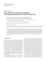
The reference network configuration is sketched in Figure 4.
Internet connectivity is provided to the WMN by the New
Delhi mesh gateway. The Rome desktop provides services
such as DHCP, Radius, and PBX (Private Branch exchange).
Finally, the Quito laptop acts as end-user’s device exploiting
the standard WiFi Hotspot provided by the Alix 6 mesh
router. The network implements a three-tiers architecture [2]
where traffic generated my end-users (first tier) is relayed
to the destination by the mesh backbone (second tier).
Internet-working with external networks (i.e., the Internet)
is provided by dedicated nodes called mesh gateway that
can exploit aforementioned backhauling technologies (third
tier).
The target of the measurement campaign carried over
the WING/WORLD testbed aimed at evaluating the time
spent by mesh gateway to switch to another backhauling
EURASIP Journal on Wireless Communications and Networking 9
Server
(Rome)
Router
Switch
Internet
Alix 1
(New Delhi)
Alix 4
Alix 3
Alix 2
Alix 5
Alix 6
Laptop
(Quito)
Access
point
Figure 4: Network configuration used to assess the performances of the performances of the self-configuring and self-healing backhauling
technologies.
technology when the current one is experiencing service
outagesaswellastoreverttotheoriginalconfiguration
when connectivity has been restored. In order to do so, the
following steps have been undertaken.
(1) The mesh gateway is connected to the Internet using
a wired connection (Ethernet).
(2) The Quito wireless client associates to the WiFi
Hotspot provided by an the Alix 6 mesh router.
(3) The wired connection is made unavailable by yanking
the Ethernet cable from the mesh gateway. This step
triggers the transition Wired
→ Wireless.
(4) The wireless connection is made unavailable by
turning off the WiFi Access Point. This step triggers
the transition Wireless
→ UMTS.
(5) The wireless connection is restored. This step triggers
the transition UMTS
→ Wireless.
(6) The wired connection is restored. This step triggers
the transition Wireless
→ Wired.
Switching time has been evaluated in two different
scenarios. In the former one, end-users’ Internet connectivity
has been assessed by continuously pinging a remote host
( Ping period has been
set to 200 ms. In the second scenario, a synthetic traffic
flow has been generated from Quito to Rome. The traffic
flow has been modeled according to the parameters of the
G.729.3 codec [29], a widely used VoIP codec. The G.729.3
VoIP codec generates 33 pkts/s; each packet contains 3 voice
samples (10 bytes each) producing a final bit-rate of 8 kbits/s.
All measurements are averaged over 10 runs.
The results of the first scenario are reported in Figure 5.
The average Round-Trip-Times (RTTs), estimated using
the ping command, are 50.2 ms, 51.7 ms, and 167.8 ms,
respectively, for the Ethernet, WiFi, and UMTS backhauls.
Confidence intervals are smaller than 2 ms over either
backhaul links.
0
40
80
120
160
200
RTT (ms)
1 50 100 150 200 250 300 350 400 450 500 550
Sequence number
Figure 5: Sequence number (SN) versus Round-Trip-Time (RTT)
as reported by the ping command. Each point represents a single
RTT value. This graph shows the Ethernet/Wifi transition (SN
between 120 and 220), the WiFi/UMTS transition (SN between 270
and 305), the UMTS/WiFi transition (SN between 570 and 620),
and the WiFi/Ethernet transition (SN between 770 and 780).
0
6
12
18
24
30
Time (s)
Ethernet-
WiFi
WiFi-
ethernet
WiFi-
UMTS
UMTS-
WiFi
Ethernet-
UMTS
UMTS-
Ethernet
Confidence interval 95%
Switching time
Figure 6: Backhaul switching time estimated using a synthetic UDP
stream modeled according the parameter of the G.729.3 VoIP codec.
This graph shows the backhaul switching time for all the possible
transition. Each point is on average of 10 runs.
The results of the second scenario are reported in
Figure 6 and summarized in Ta bl e 3.Asitcanbeseen
from the picture, a transition that is the result of a service
disruption (Ethernet
→ Wireless, Wireless → UMTS,and
Ethernet
→ UMTS) requires a longer switching time than
a transition that is reverting the backhaul, to its original
configuration. The reason for this behavior lies in the fact
10 EURASIP Journal on Wireless Communications and Networking
Table 3: Average backhaul switching times estimated using a
synthetic UDP stream. Confidence intervals (95%) are shown in
parenthesis. Results are in seconds.
From → To E t h e r n e t Wi F i U M T S
Ethernet — 10.6 (1.3) 25.9 (1.5)
WiFi 2.3 (0.4) — 25.8 (1.9)
UMTS 2.8 (0.4) 9 (0.2) —
that in the former case, about 6 seconds are spent by the
mesh gateway to negotiate its IP address with the DHCP
server. Moreover, in the transition to the UMTS backhaul a
considerable amount of time is spent in the PPP negotiation
phase with the UMTS carrier. On the other hand, in restoring
a backhaul link, the mesh gateway can first complete the IP
negotiation phase and then it can switch its default route to
the new link.
4.2. Multiradio. The WING/WORLD toolkit can exploit
multiple radios per mesh router, allowing simultaneous
transmissions and reducing intrapath interference by tuning
the mesh radios on non-overlapping channels. The Inter-
ference and Traffic Aware Channel Assignment (ITACA)
algorithm has been developed in order to both assign the
channels efficiently by taking into account the effects of
traffic and interference patterns and to maintain topological
connectivity. ITACA uses the Channel Assignment Server
(CAS), which can be colocated with the mesh gateways, as a
central node to collect information from the network and to
assign channels to each radio interfaces. The objective of the
CAS is to minimize the interference between mesh routers,
and also to minimize the interference between the mesh
network and other colocated wireless networks. It adopts
a hybrid approach in assigning channels, combining pseu-
dostatic default channel assignment, and dynamic channel
assignment. It is worth noting that our approach ensures that
channel assignment does not alter the network topology by
mandating that one radio on each mesh router must operate
on a default channel.
ITACA assigns channels considering both interference
and traffic distribution. When trafficishomogeneously
distributed among all nodes, ITACA assigns channels starting
from the gateway, selecting links with the best metric.
This approach is not optimal in case of traffic that is not
homogeneously distributed among all nodes. In order to
address such case, we consider the coefficient of variation of
the aggregated traffic crossing each link. If this coefficient is
greater than a threshold (80% in our implementation), we
give higher priority to links transmitting more data while
assigning channels. Otherwise, if the coefficientissmaller
than the threshold, our scheme sorts links considering only
interference information, thus giving higher priority to links
emanating from the gateway and going toward the edges of
the network. A multiradio conflict graph model [30] is used
to estimate and model the interference within the network
and also between the network and other colocated wireless
transmitters. The Coefficient of Variation (c
v
)isdefinedas
0.5
1.5
0
Throughput
(Mb/s)
500 1000 1500 2000 2500 3000 3500
Time (s)
BSF
ITACA
(a) Aggregated throughput
0
100
200
0
Delay (ms)
500 1000 1500 2000 2500 3000 3500
Time (s)
BSF
ITACA
(b) End-to-end delay
Figure 7: Performance improvement of ITACA with respect to the
dynamic channel assignment algorithm BSF-CA.
the ratio between the standard deviation (σ) and the mean
value (μ):
c
5
=
σ
μ
,
(4)
where mean value (μ) and standard deviation (σ)are
respectively defined as:
μ
=
1
N
N
i=1
x
i
, σ =
1
N
N
i=1
x
i
−μ
2
.
(5)
The ITACA algorithm is being currently evaluated over the
WING testbed to assess performance and the effectiveness
of the channel assignment strategy with respect to the
operation of the mesh network. The ITACA algorithm
has already been implemented and tested using the NS-2
simulator [31]. Figure 7 shows the observed performance
improvement of ITACA with respect to a dynamic channel
assignment algorithm, BSF-CA [32]. Results are averaged
over 10 runs. From the figure, it can be observed that ITACA
outperformsBSF-CAschemewithrespecttothroughputand
channel assignment delays. The simulations were carried out
considering the presence of external network interference.
The simulation details and the network models are presented
in [30]. The multiradio extensions and the ITACA algorithm,
implemented in NS-2, are available for public use at the
WING community website [8].
4.3. Opportunistic Scheduling. WMNs are known to be
susceptible to the “IEEE 802.11 performance anomaly” [33]
which refers to sudden performance drops that occurs when
nodes transmitting at low bit-rates due to poor channel
conditions capture the wireless medium for longer periods
of time at the expense of nodes transmitting at higher bit-
rates. Intracell airtime fairness is provided in the WING
EURASIP Journal on Wireless Communications and Networking 11
DA
1
DA
2
DA
n
···
Classifier
(DA-based)
ADRR
scheduler
Link
cache
Fair buffer
Figure 8: Block diagram for Airtime DRR Scheduler.
toolkit by the Airtime Deficit Round Robin (ADRR) link
scheduling discipline. ADRR enhances the Deficit Round
Robin (DRR) discipline by taking into account the channel
quality which in time prevents a node affected by high-packet
loss from monopolizing the wireless channels thus lowering
the performance of the whole system. It is worth underlining
that ADRR does not require modification to the standard
IEEE 802.11 MAC and can be readily implemented using
off-the-shelf components. Figure 8 depicts the main building
block of the ADRR scheduler.
The scheduler maintains a linked list of currently back-
logged queues. Each queue is associated with a counter, called
Deficit Counter, that indicates the amount of resources the
link can use in a round. At each round, the deficit counter
of the currently visited queue is increased by a fixed quantity
called Quantum. The ADRR scheduler only serves packets
whose expected transmission time is smaller than the deficit
counter. The expected transmission airtime TX
AIRTIME
for a
packet S bytes long is given by.
TX
AIRTIME
= M
ETT
S
L
Probe
,
(6)
where M
ETT
is the the link metric and L
Probe
is the size of
the probe used to compute it. Basically the transmission
airtime is the link’s metric linearly scaled in order to take
into account the size of the packet being transmitted. As a
matter of fact, given a certain bit error rate and assuming
the errors are i.i.d. (after decoding), a longer frame has a
higher probability of getting corrupted and thus will require
a longer transmission time. After a packet is sent, the deficit
counter is decreased by the expected transmission time of the
transmitted packet. A frame whose transmission time exceed
the deficit counter is held back until the next visit of the
scheduler. Empty queues are removed from list of currently
backlogged queues and their deficit counter is set to zero.
Measurements carried out over the WING/WORLD
testbed proved the capability of the ADRR scheduler to
provide performance isolation in IEEE 802.11-based WMNs.
Network topology is sketched in Figure 9(a).Inparticular,
nodes number 2, 3, and 4 are fed with a CBR connection
generatedatnodenumber1.WehavemodeledeachCBR
Table 4: Average throughput for different scheduling disciplines
(Good channel conditions). Results are in Kb/s.
Scheduler Node 2 Node 3 Node 4 Aggregated
FCFS 1869.6 1818.2 1870.7 5558.5
DRR 1857.1 1817.8 1889.2 5564.2
ADRR 2014.2 1995.4 2055.9 6065.5
connection as a single UDP stream with constant inter-
departure time (2 ms) and packet size (1460 bytes) producing
a final bit-rate of
≈ 6Mb/s.
Measurements have been carried out exploiting three
deployments scenarios differentiated by the channel condi-
tion experienced by nodes number 2. Notice that in each
deployment all nodes are in radio range. However, while
node number 3 and 4 are kept close to the gateway, node
number 2 is positioned in such a way to experience channel
condition raging from Good to Poor with an intermediate
Medium quality.
Ta bl es 4 through 6 summarize the outcomes of our
measurements campaign. Results show that the proposed
scheduler is capable of addressing the “IEEE 802.11 per-
formance anomaly” maintaining a high throughput over
reliable links (Node number 3 and 4) as opposed to both the
FCFS and the DRR policies that fail to achieve performance
isolation when node number 2 starts to experience poor
channel conditions.
As is shown in Ta bl e 4, when channel condition for node
number 2 is still good, the available resources are evenly
shared among all the nodes. However, it is worth noting
that the average throughput achieved by each node using the
ADRR is slightly higher than the throughput achieved using
both the FCFS and the DRR scheduling disciplines.
We postulate that the ADRR scheduler is capable of
exploiting channel fluctuation by opportunistically allocat-
ing more airtime to links that experience better channel
condition. We recall that the feedback mechanism embedded
in the routing metric gives the transmitting station (Node 1
in our case) the capability to schedule for transmission links
experiencing better channel conditions. Such considerations
are supported by the theoretical finding in [34] where chan-
nel fluctuations are exploited by transmitting information
opportunistically when and where the channel is strong.
As node number 2 moves away from the gateway (Tables
5 and 6), the ADRR is capable of allocating more resource to
the nodes experiencing better channel conditions, while the
other scheduling policies degrade the aggregated through-
put. In the extreme case where node number 2 experience
poor channel condition, ADRR outperforms both FCFS and
DRR by delivering a higher aggregated throughput (1.1 Mb/s
w.r.t. the baseline scenario) and by allocating to nodes
number 3 and 4 a percentage of the bandwidth which is only
slightly lower than the optimal case.
4.4. TrafficAggregation.In order to increase the perfor-
mances of the WING testbed, we implemented a packet
aggregation technique capable of reducing the overhead due
12 EURASIP Journal on Wireless Communications and Networking
Alix 1
Alix 2 Alix 4
Alix 3
(a) Star-shaped
Alix 3
Alix 2 Alix 4Alix 1
(b) String
Figure 9: Network topologies exploited during the measurement campaign.
DA
1
DA
2
DA
n
···
Classifier
(DA-based)
MSDU
aggregator
Round robin
scheduler
Link
cache
Aggregation buffer
Figure 10: Block diagram for Aggregation Buffer.
Table 5: Average throughput for different scheduling disciplines
(Medium channel conditions). Results are in Kb/s.
Scheduler Node 2 Node 3 Node 4 Aggregated
FCFS 1626.2 1579.1 1616.5 4821.9
DRR 1751.0 1709.6 1785.3 5245.9
ADRR 1751.6 2024.8 2074.2 5850.6
Table 6: Average throughput for different scheduling disciplines
(Poor channel conditions). Results are in Kb/s.
Scheduler Node 2 Node 3 Node 4 Aggregated
FCFS 1364.8 1318.7 1298.4 3981.9
DRR 1399.1 1340.9 1323.3 4063.3
ADRR 1107.2 1993.6 2038.8 5139.6
to both protocol headers and the channel contention by
concatenating several MAC Service Data Units (MSDUs)
to form the data payload of a large MAC Protocol Data
Unit (MPDU). Such packet aggregation scheme leverages the
channel probing functionalities of mesh routers in order to
compute the optimal saturation burst length. The building
blocks of the Aggregation Buffer and their relationships are
sketched in Figure 10.
Incoming MAC frames are first classified according to
their destination address and then fed to a different queue.
For each queue, an A-MSDU is generated when either an
aggregation timer is expired or a burst of optimal length can
be generated. The ETT metric is exploited as a cross-layer
technique in order to match link layer parameters with our
adaptive traffic aggregation policy.
Aggregation and deaggregation are performed at each
hop. Albeit such an approach could lead to increasing delays
as the number of hops increases, we postulate that, at inter-
mediate nodes, medium access delay is sufficient to collect
enough packets so that burst generation is triggered by the
optimal frame length without incurring in any aggregation
delay. In our measurement settings, each mesh node sustains
the same traffic, consisting in an increasing number of
VoIP sessions plus an additional background traffic modeled
according to a TCP socket working in saturation regime.
Streams configuration is sketched in Figure 9(b) where VoIP
bundles and TCP flows are represented respectively by
dashed and solid lines. Each VoIP call has been emulated
as single UDP stream modeled according to the parameters
of the G.729.3 codec [29]. A typical VoIP source tends to
transmit a large number of packets with a small payload, and
such a combination is known to lead to large transmission
overheads [35] in that a considerable amount of time is
wasted in the contention phase and in sending headers and
acknowledgments.
The outcomes of the measurements campaign are
reported in Figure 11. As it can be seen from the figure,
our adaptive aggregation policy provides almost a factor 3
performance increase, since the number of sustained sessions
reaches 28, whereas the plain IEEE 802.11 protocol allows for
just 8-9 VoIP sessions.
4.5. Authentication, Authorization, and Accounting. End-
users access to the WING/WORLD testbed is performed
through a captive portal. Captive portals leverage a common
web-browser as a secure authentication device, which in
time delivers service providers with a standard mean to
extend their hotspot coverage using WMN technology while
maintaining well-established Authentication, Authorization,
and Accounting (AAA) practices.
A captive portal forces an HTTP client on a generic
network to see an authentication page before using the
Internet normally. In order to achieve such a goal, a captive
portal must intercept all packets, regardless of address or
EURASIP Journal on Wireless Communications and Networking 13
0
50
100
150
200
250
300
350
400
Average delay (ms)
5101520253035
Number of concurrent flows
w/o aggregator
w/aggregator
(a) Average delay versus number of concurrent
flows
0
5
10
15
20
25
30
35
40
45
50
Packet loss (%)
5101520253035
Number of concurrent flows
w/o aggregator
w/aggregator
(b) Average packet loss versus number of concur-
rent flows
0
10
20
30
40
50
60
70
80
90
100
R-factor
5101520253035
Number of concurrent flows
w/o aggregator
w/aggregator
(c) Average R-Factor versus number of concur-
rent flows
Figure 11: Performance measurements results with background interference.
port, until the user opens a browser and tries to access
the Internet. At that time the browser is redirected to an
authentication page. The captive portal authenticates the
end-user using against a centralized users directory using a
suitable protocol. In our case, the RADIUS [36]protocolhas
been chosen to provide centralized AAA management for
end-users. The main building blocks that compose a captive-
portal-based end-users access management system are shown
in Figure 12.
As the result of a successful authentication the captive
portal will update the users directory with the details about
the newly authenticated user (MAC/IP address, login time,
etc.) and will grant its IP address with the right to access
the Internet. Additionally, the captive portal can also set QoS
routing rules so that they get provisioned a certain amount
of bandwidth or cap to the amount of data transfered.
CoovaChilli [37] has been chosen as wireless LAN access
point controller. It supports web-based login (through a cap-
tive portal), which is today’s standard for public HotSpots,
WISP “smart-client” authentication, and it supports Wi-Fi
Protected Access (WPA and WPA2). FreeRADIUS [38]isa
high-performance and highly configurable RADIUS server.
It supports many database back-ends ranging from flat-text
files, up to RDBMS and LDAP servers. It also supports many
authentication protocols such as PAP, CHAP, and so forth.
It must be underlined at this point that the opportunity
to provide access to a general audience people to the
WMN infrastructure is a critical point for a testbed, since
it enables to offer a realistic load to the network and to
capture feedback on the users’ perceived quality of the
considered architecture (this last version currently under
implementation).
As the result of a successful authentication, the captive
portal will update the users directory with the details about
the newly authenticated user (MAC/IP address, login time,
etc.) and will grant its IP address with the right to access
the Internet. Additionally, the captive portal can also set QoS
routing rules so that they get provisioned a certain amount
of bandwidth or cap to the amount of data transferred.
5. Comparison with Other Architectures
In this section, we briefly survey some of the most interesting
multiradio testbeds currently available in the WMN scene.
It is not the authors’ intention to provide and exhaustive
coverage of all the academic and industrial efforts in this
area, instead, we concentrate on solution based on off-the-
shelf components and exploiting open-source software. We
decided to focus only on multiradio solutions in that, albeit
a considerable number of prototypes have been developed
and deployed by both the academic and the industrial
worlds, little efforts have been dedicated to implement and
deploy a multiradio solutions for WMNs. The vendors
which have been selling wireless mesh solutions of course
do implement some of form multichannel architecture,
but they are obviously very reluctant to release those
information. Hence the research in WMNs field lacks
from a comprehensive perspective a realistic architecture
for distributed channel assignment in multiradio WMNs.
The most relevant implementations of IEEE 802.11-based
multiradio/multichannel WMNs are summarized in Ta bl e 7.
For the considered WING/WORLD toolkit, two columns are
provided: the first related to the version used at the time of
this writing in our deployment, and the second related to the
next release currently under development.
5.1. MCL. The Mesh Connectivity Layer (MCL) is an exper-
imental Microsoft Windows driver developed by Microsoft
Research and released under a Shared Source License. MCL
implements an interposition layer between layer 2 (the link
layer) and layer 3 (the network layer) of the standard ISO/OSI
model. It is sometimes referred to as layer 2.5. To the higher
layers, MCL appears to be just another Ethernet link, albeit
a virtual one. To the lower layers, MCL appears to be just
another protocol running over the physical link. MCL routes
using a modified version of DSR [39] called MultiRadio Link
Quality Source Routing (MR-LQSR) [22]. LQSR assigns a
weight to each link. This weight is the expected amount
of time it would take to successfully transmit a packet
14 EURASIP Journal on Wireless Communications and Networking
Radius
Internet
Coova-chilliWe bs er ver
(captive portal) (access controller)
Mesh router
Enforced until
authentication
Hotspot
Authentication, authorization,
and accounting
Figure 12: Building blocks of the captive-portal based end-users access management system. Solid lines represent physical communication
path, while dashed lines represent logic interaction among the different components.
Table 7: Comparison between different IEEE 802.11-based multiradio/multichannel WMNs implementations.
Hyacinth
MCL/DCA-MCL DMesh ROMA
WING/WORLD
WING/WORLD
2.0
Project Type
Academic
Academic Academic Academic
Academic —
License
GPL/BSD
MSR-SSLA n.a. n.a.
BSD —
OS
GNU/Linux
MS Windows XP GNU/Linux GNU/Linux
GNU/Linux —
Routing Protocol
Spanning tree
MR-LQSR DOLSR ROMA
SRCR MR-SRCR
Routing Metric
Hop-count,
Residual Link
Capacity
WCETT ETT SIM
ETT WCETT
Management
No
No No No
Web-based
management
dashboard
Decentralized
network
monitoring and
management
QoS support
No
No No No
Ye s ( D i ffServ) Yes (DiffServ)
Users management
No
No No No
WPA-PSK,
Access
Controller
(CoovaChilli)
∗
—
∗
An external RADIUS server is required for full Authentication, Authorization, and Account (AAA) services.
of some fixed size on that link. In addition, the channel,
the bandwidth, and the loss rate are determined for every
possible link. This information is sent to all the nodes.
Based on this information, LQSR uses a routing metric
called Weighted Cumulative Expected Transmission Time
(WCETT) to define the best path for the transmission of
data from a given source to a given destination. Channel
assignment is static and must be performed manually by the
network designer.
An extension to MCL, featuring distributed channel
assignment (DCA-MCL in the comparison table), is pro-
posed in [40]. The distributed channel assignment scheme
proposed by the authors selects channels that are least used
by each node’s neighbours. No common channel is used in
order to keep the network connected. The algorithm does
not need a common signaling channel to keep the network
connection. The protocol has been implemented and tested
over a 14-nodes testbed. Routes are selected using the MR-
LQSR routing protocol using the WCETT metric, a routing
metric designed to select channel diverse path in multiradio
environments.
5.2. Hyacint. Hyacinth is a multichannel WMN developed
by the Experimental Computer System Lab at the Stony
Brook University (New York) and built using off-the-
shelf components. Each Hyacinth node is equipped with
multiple IEEE 802.11 radios operating in ad hoc mode.
Internetworking with mobile stations is made possible by
atraffic aggregation device embedded in each mesh node.
Each WMN nodes interacts with individual mobile stations
through the traffic aggregation device and is responsible
EURASIP Journal on Wireless Communications and Networking 15
of assigning mesh-wide unique IP addresses to the mobile
stations. A joint centralized channel assignment and routing
algorithm has been implemented in order to build and
maintain a network spanning tree rooted at each gateway
in the network. The protocol does not rely on a common
signaling channel to keep the network connected. Hyacinth
has been implemented and tested over a small-scale indoor
testbed consisting of 9 nodes.
5.3. Mcube. Mcube [41] is a modular, multiradio, WMN
designed and developed by the Mobility Management and
Networking Laboratory (MOMENT Lab) at UC Santa
Barbara. Mcube shows a modular wireless mesh router
architecture called split wireless router.Asplit wireless router
is composed of multiple distinct processing nodes, each
equipped with a single radio. Such a design allows for easily
extensible wireless mesh routers and alleviates the detri-
mental self-interference problems that can occur between
commodity radios. Channel assignment is performed in
a centralized manner; more specifically information about
network topology are first collected then the topology and
interference aware channel assignment algorithm (TIC)
is executed in a central server, and finally the channel
assignments are disseminated to the mesh routers. The
proposed architecture has been validated using a 20-nodes
WMN consisting of 46 IEEE 802.11a/g radios. Results
show that an 802.11a dual-radio split router is able to
forward aggregate TCP traffic over 15 Mbps. In contrast,
a single-unit multiradio router is able to operate at only
2 Mbps because of inter-radio interference. Compared to
dual channel assignment schemes (e.g., Microsoft’s MCL),
TIC’s channel selection technique delivers TCP performance
improvement in 30%–100% range.
5.4. DMesh. DMesh [12] is an extension to MAP
(Mesh@Purdue) [42], a WMN testbed developed and
deployed by Purdue University. DMesh exploits both
directional antennas for spatial separation and multiple
orthogonal channels for frequency separation to provide
significantly increased throughput. The Directional OLSR
(DOLSR) routing protocol has been developed along
with a channel assignment algorithm in order to take
advantage of directional antennas setup. DOLSR extends
the OLSR protocol assisting the physical formation of
high throughput routing trees rooted at the gateways
using practical directional antennas, sets up and maintain
corresponding routing state, and performs distributed
channel assignment. The proposed architecture has been
evaluated using both simulation and experiments ran over a
mesh network testbed. Results show that, compared with the
omnidirectional/multichannel configuration, the proposed
architecture improves packet delivery ratio and throughput
and drastically lowers average per-packet delay.
5.5. ROMA. ROMA is a joint distributed channel assign-
ment and routing scheme developed by Networking and
Wide-Area Systems Group (NEWS) at the New York Uni-
versity. Channel assignment is performed by the network’s
gateway that broadcast a channel sequence to the other
nodes. Channel allocation sequences are computed in such
a way that intrapath interference is eliminated. Moreover,
ROMA included a measurement driven routing metric
inspired by mETX [43] and taking into account link delivery
ratio, fluctuations, and external interference. The protocol
has been tested on a 24-node dual-radio testbed. Results
show that ROMA can achieve high end-to-end throughput
and adapts well to changing network conditions.
6. Use Cases
In this section, we shall identify and describe a set of potential
use cases for the WING/WORLD toolkit. It is not the authors’
intention to survey all the possible application scenarios for
WMNs, for such a topic the reader is redirected to [1],
instead we aim at providing a set of guidelines for designing
and deploying a WING/WORLD-based mesh network.
Unlike the other academic testbeds and prototypes, the
WING/WORLD toolkit provides a comprehensive wireless
mesh networking solution capable of supporting production
level deployments as well as experimentally driven research
activities. Moreover, unlike commercial solutions, which are
typically monolithic with limited customization possibilities,
the “open” philosophy that characterizes the WING/WORLD
project empowers researcher and pratictiones with a power-
full tool for implementing and testing innovative solutions.
The following usage cases have been identified as the
most interesting for the WING/WORLD toolkit.
(i) Increased coverage in outdoor WiMAX networks.A
hybrid WiMAX/WiFi mesh architecture can decrease
the number of WiMAX base stations needed to
obtain good coverage. An umbrella coverage model
can be envisioned where WiMax technology is used
at the third tier of the network architecture to provide
connectivity to a multitude of WiFi-based WMNs.
Albeit only Ethernet, WiFi, and UMTS backhauls are
currently supported by our platforms, its modular
design can be easily extended to support other
technologies using a dedicated API.
(ii) Reduced dead zones. In both broadband home net-
working and enterprise networks, wireless coverage
is typically realized using IEEE 802.11 WLANs. In
such a scenario, the location of the access points in
such a way to avoid dead zones is a major issue, while
deploying multiple hotspots is also problematic due
to both the costs involved and the necessity of inter-
connecting each access point using a wired backhaul.
In this scenario, the flexibility of the WING/WORLD
toolkit allows incremental and economical deploy-
ment of indoor WMNs using off-the-shelf wireless
router preloaded with the WING/WORLD toolkit.
Moreover, the embedded CPE imposes no addi-
tional hardware/software requirements on the client-
side, making it possible to leverage the entire WiFi
installed base.
16 EURASIP Journal on Wireless Communications and Networking
(iii) Fast provisioning. The self-configuring mesh back-
haul allows for drop-in network coverage only
when/where needed. In case of a fully outdoor
deployment, no additional equipment needs to be
installed on the end-user side. WING is an excellent
plug-in solution in existing and less reliable WiFi
deployments. In this scenario, the embedded AAA
features allow straightforward management of the
user base.
7. Discussion
In this paper, we presented WING/WORLD, an open wireless
mesh networking toolkit developed with the purpose of
enabling realistic studies and performance evaluation of
novel technologies and protocols. The testbed is based
on off-the-shelf hardware components (i.e., IEEE 802.11
commodity devices) and open software modules. It is based
on an “open” philosophy and aims at providing the scientific
community with a suitable tool for performance analysis
of WMNs that can be easily replicated in research centers
around the globe.
WING/WORLD differs from already existing prototypes
in that it provides a practical platform that can be used to
implement high-capacity WMNs solutions that can be used
by the research community to design and test innovative
solutions in a realistic environment as well as by end-
users and WISPs to deploy community and metropolitan
access networks. In order to achieve such goals, we designed
and developed a flexible wireless mesh networking toolkit
supporting the following.
(i) A self-configuring and self-healing modular backhaul
technology enabling mesh nodes to automatically
detect if they are relays or gateways. The node auto-
configures itself as a gateway if an IP address can
be obtained using DHCP over one of its gateway
technologies (Ethernet, WiFi, and UMTS).
(ii) An architecture for achieving both service differenti-
ation and performance isolation (at layer 2.5) in IEEE
802.11-based WMNs. While not providing strict QoS
performance bounds, the proposed scheme aims
at enhancing the perceived quality of experience
by combining opportunistic scheduling and packet
aggregation in IEEE 802.11-based WMNs and by
implementing a DiffServ-like architecture in order to
provide traffic prioritization.
(iii) A multiradio/multichannel wireless backhaul capable
of finding high performances routing paths in an
environment characterized by competing trafficflows
that cause link losses, as well as significant link
fluctuations.
(iv) A Captive portal based end-users management sys-
tem based on Coovachilli (a well-established access
control tool) and exploiting RADIUS as AAA back-
end. Such a solution allowed us to open the testbed
to both students and staff in our lab, which are using
the WMN for their daily Internet tasks.
Current efforts are devoted at devising a unified net-
work monitoring and management architecture capable
of supporting the testbed operation across its whole life
cycle starting from network deployment and profiling, to
software configuration and fault recovery. The challenges in
this area are to automate fault-management in WMN and
consequently enable the rapid deployment of WMNs. Some
solutions are already available from commercial vendors;
however, the distributed and decentralized nature of the
wireless mesh networking paradigm has a serious impact
on the design of robust and performing architectures. A
viable architecture must also support real-time node status
monitoring, experiment campaign planning and execution,
and data gathering/analysis facilities. Finally, a user-friendly
interface must be provided in order to enable effective
network management. Finally, we are currently extending
the software toolkit to support multiple radio interface using
a joint routing and channel assignment scheme derived
from the ITACA algorithm and exploiting a novel channel
aware routing metric. Preliminary results show a significant
increase in the aggregated network throughput due to the
better spatial reuse of the wireless medium.
Future work is aimed at further improving the self-
adaptation capabilities of the WING/WORLD toolkit by
borrowing concept from cognitive radios and cognitive
networks with the purpose of enabling the validation of
several interesting concepts nowadays present in the scientific
literature but still in the design/analysis phase.
Acknowledgment
This work was partially supported by the Italian Ministry
of Scientific Research (MIUR) within the framework of
the Wireless Mesh Network for Next-Generation Internet
(WING) project (Grant number RBIN04M292) and of the
Wireless multiplatform mimo active access networks for
QoS-demanding muLtimedia Delivery (WORLD) project
(Grant number 2007R989S).
References
[1] I. F. Akyildiz, X. Wang, and W. Wang, “Wireless mesh
networks: a survey,” Computer Networks,vol.47,no.4,pp.
445–487, 2005.
[2] R. Bruno, M. Conti, and E. Gregori, “Mesh networks: com-
modity multihop ad hoc networks,” IEEE Communications
Magazine, vol. 43, no. 3, pp. 123–131, 2005.
[3] “Tropos,” />[4] “Firetide,” http://www.firetide.com/.
[5] “Strix,” />[6] “LocustWorld,” />[7] “Meshdynamics,” />[8] “Wing Project,” .
[9] “World Project,” .
[10] I. Chlamtac, M. Conti, and J. J N. Liu, “Mobile ad hoc
networking: imperatives and challenges,” Ad Hoc Networks,
vol. 1, no. 1, pp. 13–64, 2003.
EURASIP Journal on Wireless Communications and Networking 17
[11] R. Draves, J. Padhye, and B. Zill, “Comparison of routing
metrics for static multi-hop wireless networks,” in Proceedings
of the ACM Conference on Computer Communications (SIG-
COMM ’04), pp. 133–144, Portland, Ore, USA, 2004.
[12] S. M. Das, H. Pucha, D. Koutsonikolas, Y. C. Hu, and D.
Peroulis, “DMesh: incorporating practical directional anten-
nas in multichannel wireless mesh networks,” IEEE Journal on
Selected Areas in Communications, vol. 24, no. 11, pp. 2028–
2039, 2006.
[13] K. R. Chowdhury and I. F. Akyildiz, “Cognitive wireless mesh
networks with dynamic spectrum access,” IEEE Journal on
Selected Areas in Communications, vol. 26, no. 1, pp. 168–181,
2008.
[14] S. Ghamri-Doudane, D. Parker, and N. Agoulmine, “A cluster-
based middleware for infrastructure wireless Mesh networks,”
in Proceedings of the IEEE Wireless Communications and
Networking Conference (WCNC ’08), pp. 3045–3050, Las
Vegas, Nev, USA, 2008.
[15] R. Riggio, D. Miorandi, I. Chlamtac, et al., “Hardware and
software solutions for wireless mesh network testbeds,” IEEE
Communications Magazine, vol. 46, no. 6, pp. 156–162, 2008.
[16] “OpenWRT Linux Distribution,” />[17] “GNU General Public License,” />copyleft/gpl.html.
[18]J.Case,M.Fedor,M.Schoffstall, and J. Davin, “A simple
network management protocol,” IETF RFC 1157, May 1990,
/>[19] J. Rosenberg, R. Mahy, P. Matthews, and D. Wing, “Session
Traversal Utilities for NAT (STUN),” IETF RFC 5389, October
2008, />[20] E. Kohler, R. Morris, B. Chen, J. Jannotti, and M. F. Kaashoek,
“The click modular router,” ACM Transactions on Computer
Systems, vol. 18, no. 3, pp. 263–297, 2000.
[21] A. Bicket, D. Aguayo, S. Biswas, and R. Morris, “Architecture
and evaluation of an unplanned 802.11b mesh network,” in
Proceedings of the Annual International Conference on Mobile
Computing and Networking (MOBICOM ’05), pp. 31–42,
Cologne, Germany, 2005.
[22] R. Draves, J. Padhye, and B. Zill, “Routing in multi-radio,
multi-hop wireless mesh networks,” in Proceedings of the
Annual International Conference on Mobile Computing and
Networking (MOBICOM ’04), pp. 114–128, Philadelphia, Pa,
USA, 2004.
[23] R. Riggio, D. Miorandi, and I. Chlamtac, “Airtime deficit
round robin (ADRR) packet scheduling algorithm,” in Pro-
ceedings of the 5th IEEE International Conference on Mobile Ad-
Hoc and Sensor Systems (MASS ’08), pp. 647–652, Atlanta, Ga,
USA, October 2008.
[24] R. Riggio, F. De Pellegrini, N. Scalabrino, P. Li, Y. Fang, and
I. Chlamtac, “Performance of a novel adaptive trafficaggre-
gation scheme for wireless mesh networks,” in Proceedings of
the IEEE Military Communications Conference (MILCOM ’07),
Orlando, Fla, USA, 2007.
[25] R. Riggio, D. Miorandi, F. De Pellegrini, F. Granelli, and I.
Chlamtac, “A trafficaggregationanddifferentiation scheme
for enhanced QoS in IEEE 802.11-based wireless mesh net-
works,” Computer Communications, vol. 31, no. 7, pp. 1290–
1300, 2008.
[26] S. Blake, D. Black, M. Carlson, E. Davies, Z. Wang, and W.
Weiss, “An architecture for differentiated services,” IETF RFC
2475, December 1998, />[27] “The olsr.org OLSR daemon,” />.
[28] “B.A.T.M.A.N., Better Approach to Mobile Ad-Hoc Network-
ing,” />[29] “Coding of speech at 8 kbit/s using conjugate-structure
algebraic-code-excited linear prediction (CS-ACELP),” ITU-T
Recommendation G.729, June 2007.
[30] M. Slongo and T. Rasheed, “ITACA: channel assignment in
wireless mesh networks,” Tech. Rep. TR-200800025, CREATE-
NET, 2008, />[31] “ns-2,” />[32] K. N. Ramachandran, E. M. Belding, K. C. Almeroth, and
M. M. Buddhikot, “Interference-aware channel assignment in
multi-radio wireless mesh networks,” in Proceedings of the 25th
IEEE International Conference on Computer Communications
(INFOCOM ’06), Barcellona, Spain, 2006.
[33] M. Heusse, F. Rousseau, G. Berger-Sabbatel, and A. Duda,
“Performance anomaly of 802.11b,” in Proceedings of the
IEEE International Conference on Computer Communications
(INFOCOM ’03), vol. 2, pp. 836–843, San Francisco, Calif,
USA, 2003.
[34] D. N. C. Tse and S. V. Hanly, “Multiaccess fading channels—
part I: polymatroid structure, optimal resource allocation
and throughput capacities,” IEEE Transactions on Information
Theory, vol. 44, no. 7, pp. 2796–2815, 1998.
[35] S. Ganguly, V. Navda, K. Kim, et al., “Performance optimiza-
tions for deploying VoIP services in mesh networks,” IEEE
Journal on Selected Areas in Communications, vol. 24, no. 11,
pp. 2147–2158, 2006.
[36] S. Willens, A. Rubens, and W. Simpson, “Remote Authenti-
cation Dial in User Service (RADIUS),” IETF RFC 2865, June
2008, />[37] “CoovaChilli Access Controller,” />CoovaChilli.
[38] “The FreeRADIUS Project,” />[39] D. Johnson, Y. Hu, and D. Maltz, “The dynamic source routing
protocol (DSR) for mobile ad hoc networks for IPv4,” IETF
RFC 4728, February 2007, />[40] B J. Ko, V. Misra, J. Padhye, and D. Rubenstein, “Distributed
channel assignment in multi-radio 802.11 mesh networks,”
in Proceedings of the IEEE Wireless Communications and
Networking Conference (WCNC ’07), pp. 3981–3986, Hong
Kong, 2007.
[41] K. Ramachandran, I. Sheriff, E. M. Belding, and K. Almeroth,
“A multi-radio 802.11 mesh network architecture,” Mobile
Networks and Applications, vol. 13, no. 1-2, pp. 132–146, 2008.
[42] “Purdue university wireless mesh network testbed,”
/>[43] C. E. Koksal and H. Balakrishnan, “Quality-aware routing
metrics for time-varying wireless mesh networks,” IEEE
Journal on Selected Areas in Communications, vol. 24, no. 11,
pp. 1984–1994, 2006.