Báo cáo hóa học: " Research Article Joint Multilevel Turbo Equalization and Continuous Phase Frequency Shift Keying" pot
Bạn đang xem bản rút gọn của tài liệu. Xem và tải ngay bản đầy đủ của tài liệu tại đây (797.49 KB, 8 trang )
Hindawi Publishing Corporation
EURASIP Journal on Wireless Communications and Networking
Volume 2008, Article ID 458785, 8 pages
doi:10.1155/2008/458785
Research Article
Joint Multilevel Turbo Equalization and Continuous
Phase Frequency Shift Keying
Oguz Bayat,
1
Niyazi Odabasioglu,
2
Onur Osman,
3
Osman N. Ucan,
2
Masoud Salehi,
4
and Bahram Shafai
4
1
Electronics and Communication Engineering Department, Be ykent University, Buyukcekmece, 34500 Istanbul, Turkey
2
Electrical and Electronics Engineering Depart ment, Istanbul University, Avcilar, 34320 Istanbul, Turkey
3
Electronics and Telecommunications Engineering Depar tment, Engineering Faculty, Halic University, Sisli, 34381 Istanbul, Turkey
4
Electrical and Computer Engineering, Northeastern University, 360 Huntington Avenue, Boston, MA 02115, USA
Correspondence should be addressed to Oguz Bayat,
Received 2 May 2008; Revised 21 July 2008; Accepted 31 December 2008
Recommended by Huaiyu Dai
A novel type of turbo coded modulation scheme, called multilevel turbo coded-continuous phase frequency shift keying (MLTC-
CPFSK), is designed to improve the overall bit error rate (BER) and bandwidth efficiency. Then, this scheme is combined with a
new double decision feedback equalizer (DDFE) to remove the interference and to enhance BER performance for the intersymbol
interference (ISI) channels. The entire communication scheme is called multilevel turbo equalization-continuous phase frequency
shift keying (MLTEQ-CPFSK). In these schemes, parallel input data sequences are encoded using the multilevel scheme and
mapped to CPFSK signals to obtain a powerful code with phase continuity over the air. The performances of both MLTC-CPFSK
and MLTEQ-CPFSK systems were simulated over nonfrequency and frequency-selective channels, respectively. The superiority of
the two level turbo codes with 4CPFSK modulation is shown against the trellis-coded 4CPFSK, multilevel convolutional coded
4CPFSK, and TTCM schemes. Finally, the bit error rate curve of MLTEQ-CPFSK system over Proakis B channel is depicted and
ISI cancellation performance of DDFE equalizer is shown against linear and decision feedback equalizers
Copyright © 2008 Oguz Bayat et al. This is an open access article distributed under the Creative Commons Attribution License,
which permits unrestricted use, distribution, and reproduction in any medium, provided the original work is properly cited.
1. INTRODUCTION
With the development of the wireless communication
industry, wireless data communications have become a
very important research area for many scientists. As a
result, tremendous improvements have occurred in coding,
modulation, and signal processing subsystems to provide
burst rates along with power efficiency at low bit error rates.
First, conventional turbo code was found to be very attractive
in the last decade [1], since turbo code reached theoretical
limits in an iterative fashion at low signal-to-noise ratio with
a cost of a low code rate and bandwidth expansion. Several
years later, the compensation for bandwidth expansion and
the low code rate was realized by applying multilevel and
trellis-coded modulation to turbo code, known as multilevel
turbo codes (MLTCs) [2, 3] and turbo trellis-coded modu-
lation (TTCM) [4, 5], respectively, in the literature. These
techniques increase the spectral efficiency of the coding via
concatenating higher-order modulation using PSK or QAM
modulations [6]; however, these communication models
have phase jumps in their modulated signals. Continuous
phase modulation (CPM) has explicit advantages in deep
space and satellite communications, such as having low
spectral occupancy property. Thus, to improve the bandwith
usage further, MLTC design is concatenated and investigated
with CPM modulation in this research.
MLTC is modeled by applying separate turbo encoders
at each level. Each turbo encoder processes the information
sequence simultaneously. For each level of the mutilevel
encoder, there exists a corresponding decoder defined as a
stage. The output of one stage is utilized at the decoder of
the following stage in the decoding flow, known as multistage
decoding [7].
The CPM model that is used with the MLTC is composed
of a continuous-phase encoder (CPE) and a memoryless
mapper (MM). The CPE is a convolutional encoder produc-
ing codeword sequences that are mapped onto waveforms
by the MM, creating a continuous-phase signal. CPE-related
schemes have better BER performance than systems using
the traditional approach for a given number of trellis states
2 EURASIP Journal on Wireless Communications and Networking
u
k
m
k
CPFSK
demod.
1
Signal set
selection & r
computation
Joint equalization &
turbo decoder
2
Signal set
selection & r
computation
Signal set
selection & r
computation
n
ISI
Turbo
n
CPE
M-CPFSK
1
Joint equalization &
turbo decoder
Joint equalization &
turbo decoder
encoder
Turbo
encoder
x
1
k
x
n
k
d
1
k
d
n
k
r
1
k
r
2
k
r
n
k
τ
nτ
d
1
k
d
1
k
d
2
k
d
n
k
d
n−1
k
.
.
.
.
.
.
.
.
.
.
.
.
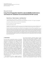
Figure 1: MLTEQ-CPFSK structure block diagram.
due to larger Euclidean distances. When the decomposed
structure of CPM is considered, joint trellis coded and CPM,
and joint multilevel convolutional code and CPM systems
can be designed as in [8, 9].
For achieving a low bit error rate (BER) over a severe
ISI channel, the double decision feedback equalization is
designed for MLTC-CPFSK system [10–12]. It is well know
that maximum a posteriori probability (MAP) and soft out-
put Viterbi algorithm-based equalizers are very effective, but
having very high complexity, which is not applicable to our
design since our transmission scheme has high complexity.
Performances of traditional low-complexity equalizers such
as linear equalizer (LE) and decision feedback equalizers
(DFE) are not effective under severe channel conditions.
To close the performance gap between high- and low-
complexity equalizers, DDFE is proposed and implemented
into the MLTC-CPFSK system. Thus, the effect of a severe ISI
channel is mitigated by the equalization process and then the
equalized information passes through the MAP algorithm-
based decoders which decode the two encoded streams by
exchanging the soft decisions.
In this paper, Section 2 explains the design of multilevel
turbo encoder with CPFSK modulation. Section 3 describes
the DDFE-based turbo equalization receiver scheme. In
Section 4,the performances of the proposed MLTC-CPFSK
and MLTEQ-CPFSK schemes are presented over AWGN,
Rician, Rayleigh, and Proakis B channels, respectively, and
the conclusion is stated at the last section.
2. THE DESIGN OF MULTILEVEL TURBO
ENCODER USING CPFSK
M-ary continuous phase frequency shift keying (M-CPFSK)
is a special form of M dimensional CPM. In the literature,
Rimoldi firstly derived the tilted-phase representation of
CPM in [13], with the information-bearing phase given by
φ(t, X)
= 4πh
∞
i=0
X
i
q(t − iT). (1)
The modulation index h is equal to J/P,whereJ and P
are relatively prime integers. X is an input sequence of
M-ary symbols, X
i
∈{0, 1, 2, , M − 1} i ≥ 0. T is
the channel symbol period. In CPFSK design, modulation
index h
= 1/2 is considered and the frequency pulse is a
rectangular pulse of duration LT and height 1/(2LT ), yielding
a linearly increasing/decreasing instantaneous phase φ(t, X).
In this design, full response CPFSK modulator is considered.
The phase response function q(t) is a continuous and
monotonically increasing function subject to the constraints
q(t)
=
⎧
⎪
⎪
⎨
⎪
⎪
⎩
0, t ≤ 0,
1
2
, t
≥ LT,
(2)
where L is an integer that denotes the number of memory
units in CPE. The phase response is usually defined in terms
of the integral of a frequency pulse g(t)ofdurationLT, that
is, q(t)
=
t
−∞
g(τ)dτ. For full response signaling L equals to
1, and for partial response systems L is greater than 1. Finally,
the transmitted signal u(t)isderivedas
u(t, X)
=
2E
s
T
cos
2πf
1
t + φ(t, X)+φ
0
,(3)
where f
1
is the asymmetric carrier frequency as f
1
= f
c
−
h(M − 1)/2T and f
c
is the carrier frequency. E
s
is the energy
per channel symbol and φ
0
is the initial carrier phase. We
assume that f
1
T is an integer; this condition leads to a
simplification when using the equivalent representation of
the CPM waveform.
Multilevel turbo code using CPFSK modulation consists
of many parallel turbo encoder/decoder levels. In Figure 1,
high-level block diagram of designed transceiver is shown for
n level case. There exists a binary turbo encoder at every level
of the multilevel turbo encoder, and there is a continuous-
phase encoder serially connected to the turbo encoder at the
last level. Based on Rimoldi’s model and the assumption in
[13], CPE would be a convolutional encoder. In this model,
the outside encoder is designed to maximize the Euclidean
distance between output signals whereas CPE is used to shape
the modulated signal’s spectrum. In the CPFSK design, the
state of CPE is binary and it changes with time. The phase of
Oguz Bayat et al. 3
+
+
FF
Channel
estimator
FB
1
Dec1
FB
2
Dec2
r
k
h
k
π
◦
π
1
π
◦
1
τ
τ
π
−
d
k
d
k,1
d
k,2
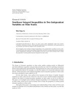
Figure 2: Joint DDFE and turbo decoder structure.
the modulated signal depends on the memoryless modulator.
The first process of the transmitter is that the information
sequence is converted from serial to parallel in the multilevel
scheme. Then, each turbo encoder processes the information
sequence simultaneously. Additionally, the outputs of the
last turbo encoders are run through the CPE. The outputs
of all encoders’ outputs and CPE output are mapped to
CPFSK signals. In Figure 4, the two-level multilevel turbo
transmission system (2LTC-4CPFSK) is illustrated in detail
since this research simulations were performed on a two-level
model. In each level, a 1/3 turbo encoder is demonstrated
with recursive systematic convolutional (RSC) encoders
having memory size M
s
= 2asinFigure 4(a). For mapping
the encoders’ outputs to 4CPFSK signals, the first and
second bits are taken from the first and second level of
turbo encoder output, respectively. The third bit is obtained
from the output of the CPE. Thus, based on the output
of the encoders x
1
k
, x
2
k,1
,andx
2
k,2
, the CPFSK modulated
signals u
={u
0
, u
1
, u
2
, u
3
, u
4
, u
5
, u
6
, u
7
} are transmitted
at four different frequencies f
1
, f
1
+1/2T, f
1
+1/T,and
f
1
+3/2T. The initial and ending physical tilted phases are
0andπ as shown in Figure 5. At the receiver, 4CPFSK
signal constellation partitioning is optimized to provide low
BER for AWGN and fading channels as in [9]. The signal
set partitioning technique for 2LTC-4CPFSK signals is as
follows: depending on the estimated output bit of the first-
level turbo decoder is whether x
1
k
= 0orx
1
k
= 1, u
1
0
=
{
u
0
, u
1
, u
4
, u
5
} or u
1
1
={u
2
, u
3
, u
6
, u
7
} signal set is chosen,
respectively. Then, depending on the estimated second-level
turbo encoder output bit
{x
2
k,1
} and the CPE output bit
{x
2
k,2
}, the transmitted signal is determined as shown in
Figure 5.
3. TURBO EQUALIZATION RECEIVER SCHEME
For the kth symbol interval, a set of basis functions was
used to find the coordinates in signal space and to form
the vector u
k
in each signaling interval. Let the transmitted
MLTC-CPFSK symbol sequence be
u ={u
0
, u
1
, } and
the corresponding received sequence be
m ={m
0
, m
1
, },
where the kth received vector element equals to m
k
. In this
case, the channel output during the kth symbol interval can
be expressed as
m
k
= a
k
u
k
+ n
k
,(4)
where n
k
is kth noise vector element of the noise sequence
n ={n
0
, n
1
, } and its elements are additive white Gaussian
noise with an N
0
/2E
s
power spectral density, Es is the signal
energy per symbol, a
k
is Rician fading amplitude, which
varies by Rician probability distribution function as in
P(a)
= 2a(1 + K)e
(−a
2
(1+K)−K)
I
0
2
K(1 + K)
,(5)
where K is the Rician factor in terms of dB. We assume
that the demodulator operates over one symbol interval,
which yields a discrete memoryless channel. At the receiver,
the corrupted MLTC-CPFSK signals are processed by the
demodulator and MAP decoder to extract the information
sequence.
MLTEQ-CPFSK scheme is applied to Proakis B channel.
This channel is time-invariant ISI channel having L
2
casual,
L
1
anticasual terms and is known as severe ISI channel with
3 main taps and no precursor and postcursor taps [14]. The
outputofthechannelisequalto
m
k
=
L
2
i=−L
1
F
i
u
k−i
+ n
k
,(6)
where F
k
are the coefficients of the equivalent discrete
channel.
After the M-CPFSK modulated signals are run through
the channel, they are demodulated and then noisy demod-
ulator outputs are evaluated for every equalization and
decoding process. The following is the high-level summary
of the equalization and decoding process. In the first step,
the probabilities of received signal being zero and one is
computed as in (7) and then, the probabilities are mapped
to
{−1, 1} range via (8). In the second step, the computation
of the equivalent discrete channel taps is explained when the
channel conditions are known for the traditional decision
feedback equalizer. In our application and real applications,
the channel information is not known. Thus, the estimation
process of the channel via LMS algorithm is performed and
described. The coefficient vectors of the filters are defined
from (14) and their adaptation is explained from (15). The
DDFE equalization output is derived with (17). Finally, the
equalized information is processed by the MAP decoder as in
(18).
4 EURASIP Journal on Wireless Communications and Networking
d
k
Encoder
Encoder
Puncturer
Multiplexer
X
k
x
(1)
k
x
(0)
k
x
(2)
k
π
1
π
(a)
Systematic
data
data
SISO
dec1
SISO
dec2
Parity
Deint
Demux
d
k,1
d
k,2
d
k
d
(0)
k
d
(2)
k
d
(1)
k
I
(2)
I
(1)
I
(2)
Λ
(1)
Λ
(2)
π
◦
1
π
1
π
1
+
−
−
+
−
−
(b)
Figure 3: Turbo code structure: (a) turbo encoder structure, (b) turbo decoder structure.
At the receiver, the probabilities of the corrupted received
signals being zero and one are computed as follows:
P
st
k,0
=
(2M/2
st
)−1
j=0
P
m
k
| u
st
0,j
∝
(2M/2
st
)−1
j=0
e
|m
k
−u
st
0,j
|
2
/N
0
,
P
st
k,1
=
(2M/2
st
)−1
j=0
P
m
k
| u
st
1,j
∝
(2M/2
st
)−1
j=0
e
|m
k
−u
st
1,j
|
2
/N
0
,
(7)
where P
st
k,0
and P
st
k,1
indicate zero and one probabilities of the
received signal at time k and stage st. The partitioning stage is
equal to st
∈{1, 2, ,log
2
M}. u
st
0
, u
st
1
are the selected signal
sets at stage st.
In multilevel coding scheme, each digit of binary cor-
respondence of CPFSK signals matches to one stage from
the most significant to the least significant while the stage
number increases. Signal set is partitioned into the subsets
due to each binary digit matching stage depending on
whether it is 0 or 1. After computing the one and zero
probabilities, received signals are mapped to
{−1, 1} range
and then sent to the equalization and decoding process at
each level,
r
st
k
= 1 −
2·P
st
k,0
P
st
k,0
+ P
st
k,1
. (8)
As shown in Figure 2, DDFE structure mainly consists
of 3 linear transversal filters: the feed forward (FF) filter,
and two feedback filters (FB), a channel interleaver (π),
deinterleaver (π
◦
), and two delay components. The decoder
structure is made of two interleavers (π
1
), two deinterleavers
(π
◦
1
), a demultiplexer, and two soft input soft output (SISO)
decoders which exchange priori information as indicated in
more detail in Figure 3.
In order to reduce the notation of the equations and
figures, the notation is not changed when the information is
processed by the interleavers. Only the channel output feeds
the equalizer at the first iteration, therefore, the equalizer
uses training sequence to operate for the initial process. For
further iterations, the FF filter is fed by the channel output
and the channel estimator output. The channel estimator
uses both the hard decision of the first decoder and the
channel output to estimate the channel information. The
first FB filter uses the hard decision of the first decoder (
d
k,1
)
whereas the second FB filter uses the hard decision of the
second decoder (
d
k,2
).
In order to perform the conventional DFE equalization,
error propagation has to be ignored, which means
d = d.The
coefficient of the equalizer is computed in [7] by using mean
square error (MSE), which is based on the minimization of
the difference between the equalized data (
d
k
) and the hard
decision of the first decoder (
d
k,1
) as follows:
E
e
k
2
,wheree
k
=
d
k,1
− d
k
,(9)
d
k
=
0
j=−L
1
v
j
r
k− j
−
L
2
j=1
w
j
d
k,1− j
, (10)
where L
1
and L
2
are the numbers of feedforward and
feedback coefficients, respectively. v is the coefficient of the
FF filter, where w is the coefficient of the FB filter. By using
first orthogonality principle, the feedforward coefficients of
the filter are computed. This principle yields to the following
set of linear equations:
0
j=−L
1
v
j
Γ
tj
= F
∗
−
t
, −L
1
≤ t ≤ 0, (11)
where
Γ
tj
=
−t
n=0
F
∗
n
F
n+t− j
+ N
o
δ
tj
(12)
where t, j
=−L
1
, , −1, 0 and F is the channel tap.
The coefficient of the FB filter is computed by the second
orthogonality principle,
w
k
=
0
j=−L
1
v
j
F
k− j
, k = 1, 2, , L
2
. (13)
Oguz Bayat et al. 5
4CPFSK
MAPPER
+
+
+
+
+
+
+
+
+
+
+
+
+
d
1
k
d
2
k
x
DD
DD
DD
D
D
D
1
k
u
k
x
2
k
x
(0)
k
,1
x
(1)
k
,1
x
(2)
k
,1
x
2
k
,1
x
2
k
,2
x
(0)
k
,2
x
(1)
k
,2
x
(2)
k
,2
π
1
π
1
(a)
r
1,1
k
r
2,1
k
r
1,2
k
r
1,0
k
P
k
m
k
z
(1)
z
(1)
r
(1)
r
(1)
r
(0)
r
(0)
r
(2)
z
(2)
r
(2)
z
(2)
r
2,2
k
r
2,0
k
L
(0)
c
L
(0)
c
L
(1)
c
L
(1)
c
L
(2)
c
L
(2)
c
+
+
+
+
SISO
decoder
2,1
SISO
decoder
1,1
SISO
decoder
1,2
SISO
decoder
2,2
Signal set
selection & r
computation
Signal set
selection & r
computation
CPFSK
demodulator
Delay
I
(1)
I
(1)
I
(2)
I
(2)
τ
Λ
(1)
Λ
(2)
−
−
−
−
−
−
−
−
Λ
(1)
Λ
(2)
π
1
π
1
π
◦
1
π
1
π
1
π
◦
1
π
◦
1
π
◦
1
d
2
k
d
1
k
r
(0)
r
(0)
(b)
Figure 4: 2LTC-4CPFSK system for M
s
= 2 and without equalization: (a) encoder structure, (b) decoder structure.
Since the equivalent discrete channel taps are unknown in
most of the communication applications, the filter coefficient
cannot be computed from the equation above.
We selected LMS algorithm to determine the filter
coefficients because of its less complexity and high accuracy
on time-invariant channels at large frame sizes. By LMS
algorithm, the coefficients of channel and feedback filters
are estimated from the corrupted transmitted signal and
the hard decisions of the decoders after certain latency (τ)
is introduced to the system. After the first iteration, the
coefficient vectors of the FF, first FB, and second FBfilters are
computed, respectively, as
V
k
=
v
−L
1
(k),v
−L
1
+1
(k), ,v
0
(k)
T
,
W
k
=
w
1
(k),w
2
(k), ,w
L
2
(k)
T
,
Q
k
=
q
L
2
+1
(k), q
L
2
+2
(k), , q
L
3
+L
2
+1
(k)
T
.
(14)
6 EURASIP Journal on Wireless Communications and Networking
0 0
01
10 11
u
000
00
10 11
1
= 0
= 00
01
x
1
k
x
2
k,1
x
2
k,2
u
001
u
010
u
011
u
100
u
101
u
110
u
111
u
3
u
3
u
4
u
4
u
6
u
6
u
7
u
7
u
5
u
5
u
0
u
0
u
2
u
2
u
1
u
1
ππ
φ
n
φ
n+1
Figure 5: Set partitioning of 4CPFSK.
MLTC-CPFSK
BER
1E +00
1E
− 01
1E
− 02
1E
− 03
1E
− 04
1E − 05
1E
− 06
E
s
/N
0
(dB)
01234
AWG N- i t er 1
Rayleigh-iter1
Rician-iter1
AWG N- i t er 2
Rayleigh-iter2
Rician-iter2
AWG N- i t er 3
Rayleigh-iter3
Rician-iter3
Figure 6: Performance of the two-level turbo coding system using
4CPFSK modulation, N
= 1024.
In LMS algorithm, the coefficients of the FF and FB filters are
adapted as follows:
V
k+1
= V
k
+ Δ
V
R
k
d
k,1
− r
k
,
W
k+1
= W
k
+ Δ
W
D
k,1
d
k,1
− h
k
,
Q
k+1
= Q
k
+ Δ
Q
D
k,2
d
k,2
− d
k
,
(15)
where Δ is the step size of the LMS algorithm, and
R
k
= [r
k+L
1
(k),r
k+L
1
−1
(k), ,r
k
(k)]
T
is the vector of the
transmitted signal, and the vectors below are the hard-
decision vectors of the decoders from the previous iteration,
D
k,1
=
d
(k,1)+L
2
(k),
d
(k,1)+L
2
−1
(k), ,
d
(k,1)+1
(k)
T
,
D
k,2
=
d
(k,2)+L
3
+L
2
+1
(k), ,
d
(k,2)+L
2
+1
(k)
T
.
(16)
MLTC-CPFSK versus TTCM
BER
1E +00
1E
− 01
1E
− 02
1E
− 03
1E
− 04
1E
− 05
1E
− 06
E
s
/N
0
(dB)
123456
AWG N- i t er 1
Rician-iter1
TTCM, AWGN, iter1
TTCM, Rician, iter1
AWG N- i t er 2
Rician-iter2
TTCM, AWGN, iter2
TTCM, Rician, iter2
AWG N- i t er 3
Rician-iter3
TTCM, AWGN, iter3
TTCM, Rician, iter3
Figure 7: Performance comparison of 2LTC-4CPFSK and TTCM
systems, N
= 1024.
After the corrupted transmitted signals are filtered by FF and
first FB filters as shown in (10), it is deinterleaved (h
k
)and
subtracted from the output of the second FB filter to obtain
DDFE output (
d
k
)asbelow,
d
k
= h
k
−
L
3
+L
2
+1
L
2
+1
q
k
d
k,2
. (17)
During the initializing period, the coefficients of the FF
filter at the first iteration are estimated from the training
sequence by the LMS criterion due to the fact that the hard
decision of the decoder does not exist at the first iteration.
Therefore, the DDFE structure behaves as a linear equalizer
fed by the training sequence at the first iteration.
Eventually, the equalized information sequences (
d
k
)are
passed through the SISO decoders.In SISO decoders, the
MAP algorithm calculates the a posteriori probability of each
bit at each decoding process [15]. At the last iteration, hard
decision is computed by using the second decoder output
Λ
(2)
as follows:
d
k
=
⎧
⎨
⎩
1, if Λ
(2)
≥ 0,
0, if Λ
(2)
< 0.
(18)
4. SIMULATION RESULTS
The performance of the two-level turbo coded 4CPFSK
system is shown by plotting the bit error rate versus signal-
to-noise ratio in Figure 6. Joint two-level turbo code and
4CPFSK scheme with random interleaver size N
= 1024,
generator sequence (37, 21) in octal form, and overall rate 2/3
was simulated for AWGN, Rician (Rician fading parameter
K
= 10 dB) and Rayleigh channels. Then, the proposed
2LTC-4CPFSK scheme was compared to the known existing
multilevel schemes using CPFSK showed in [8, 9], called ref-
1 and ref-2, respectively. The code on reference one (ref-1) is
Oguz Bayat et al. 7
Table 1: Coding gains (in dB) over reference systems for P
e
= 10
−4
.
Coding gains for 2LTC-4CPFSK over ref-1
Iteration
AWGN Rician channel Rayleigh
channel (K
= 10 dB) channel
1 3.5 3.8 7.5
2 4.2 4.55 8.4
3 4.4 4.8 8.55
Coding gains for 2LTC-4CPFSK over system (S-5) in ref-2
110.80.2
2 1.7 1.55 1.1
3 1.9 1.8 1.25
binary trellis-coded 4-ary CPFSK scheme with overall rate
2/3, and the code labeled (S-5) in reference two (ref-2) is
the combined multilevel convolutional code and 4CPFSK.
The proposed system has much better performance than
ref-1 and satisfactory coding gain over ref-2 for all channel
conditions as stated in Tab le 1 . The comparison among these
systems was revealed for the fixed bit error rate 10
−4
.For
instance, the coding gain under AWGN channel between
MLTC-CPFSK and ref-1 is 3.3, 4.05, and 4.3 dB for iteration
one to three, respectively.
The proposed 2LTC-CPFSK method was also compared
with the bandwidth efficient TTCM scheme, which is shown
in Figure 7.TheTTCMmodelin[4] was simulated with
8 states, N
= 1024, 2048 bits for overall rate 1 to provide
the BER performance for AWGN and Rician (K
= 10 dB)
channels. To have a better comparison with TTCM model
at the same overall rate, we have performed MLTC-CPFSK
simulation with the same parameters as given above, except
puncturing that used this time to achieve overall rate 1.
The comparison indicates that MLTC-CPFSK system has
0.9, 1.2, and 1.3 dB coding gain against TTCM system
for first, second, and third iterations, respectively, over
AWGN channel. Also, our design has 1.7–2 dB gain over
Rician channel. This important performance difference is
achieved by MLTC-CPFSK system due to the fact that the
concatenation of the powerful multilevel turbo codes and
the CPE encoder yields higher Hamming distance and leads
to good error performance for both AWGN and Rician
channels.
The BER performance of 2LTEQ-4CPFSK is depicted
over Proakis B channel for interleaver size N
= 2048 frame
size in Figure 8. Aggressive performance of the designed
MLTEQ-CPFSK model was generated under severe ISI
channel such as BER 10
−5
was achieved at SNR 10.5 dB at
the sixth iteration. It is illustrated that significant amount of
gain is achieved at each iteration by reducing the frequency
dispersive effects of Proakis B channel. DDFE equalizer has
0.8 dB and 2.1dB gains at BER 10
−5
over conventional
DFE and minimum mean square sequence error-based LE
equalizers, respectively. DDFE equalizer provides gain at a
cost of introducing additional feedback filter and delay into
the system when compared to the complexity of the DFE
equalizer. The overall delay of the proposed systems will
be minimized to be employed in some real applications;
MLTEQ-CPFSK over Proakis B Channel
BER
1E +00
1E
− 01
1E
− 02
1E
− 03
1E
− 04
1E
− 05
E
s
/N
0
(dB)
7891011121314
LE-iter1
DDFE-iter5
DDFE-iter2
DDFE-iter6
DDFE-iter3
DFE-iter2
DDFE-iter4
Figure 8: Performance of the two-level turbo equalization using
4CPFSK modulation over Proakis B channel, N
= 2048.
however, the proposed systems are suitable for mobile data
communications, video, and audio broadcasting.
5. CONCLUSION
We have presented multilevel turbo codes scheme with
CPFSK modulation, and joint multilevel turbo equalization
scheme with CPFSK modulation in this paper. MLTC-
CPFSK design compensates the requirement of large frame
size and high iteration number to obtain low BER at low SNR
for turbo codes by adding complexity and slight latency due
to the multistage structure. As shown in Figure 7,MLTC-
CPFSK model achieves 10
−5
BER performance at the third
iteration when SNR equals to 3 dB and 3.7 dB for AWGN
and Rician channels, respectively. When we compared our
model with the well-known multilevel coded CPFSK and
TTCM schemes in the literature, we observed important
coding gains with the simulation results. Furthermore, low-
complexity DDFE equalizer was designed and its good
interference cancellation performance was presented against
LE and DFE equalizers. Eventually, satisfactory performance
results for MLTEQ-CPFSK scheme is demonstrated for
severe ISI channels.
REFERENCES
[1] C. Berrou, A. Glavieux, and P. Thitimajshima, “Near Shannon
limit error-correcting coding and decoding: turbo-codes (1),”
in Proceedings of IEEE International Conference on Communi-
cations (ICC ’93), pp. 1064–1070, Geneva, Switzerland, May
1993.
[2] L. Papke and K. Fazel, “Combined multilevel turbo-code
with MR-modulation,” in Proceedings of IEEE International
Conference on Communication (ICC ’95), vol. 2, pp. 668–672,
Seattle, Wash, USA, June 1995.
[3] D. Divsalar and F. Pollara, “Multiple turbo codes,” in Pro-
ceedings of IEEE Military Communications Conference (MIL-
COM ’95), vol. 1, pp. 279–285, San Diego, Calif, USA,
November 1995.
8 EURASIP Journal on Wireless Communications and Networking
[4] P.RobertsonandT.W
¨
orz, “Bandwidth-efficient turbo trellis-
coded modulation using punctured component codes,” IEEE
Journal on Selected Areas in Communications, vol. 16, no. 2,
pp. 206–218, 1998.
[5] W. J. Blackert and S. G. Wilson, “Turbo trellis coded modula-
tion,” in Proceedings of the Conference on Information Signals
and System (CISS ’96), Princeton, NJ, USA, March 1996.
[6] U. Wachsmann, R. F. H. Fischer, and J. B. Huber, “Multilevel
codes: theoretical concepts and practical design rules,” IEEE
Transactions on Information Theory, vol. 45, no. 5, pp. 1361–
1391, 1999.
[7] O.Bayat,B.Shafai,andO.N.Ucan,“Iterativeequalizationof
frequency selective channels,” in Proceedings of IEEE/Sarnoff
Symposium on Advances in Wired and Wireless Communica-
tion, pp. 33–36, Princeton, NJ, USA, April 2005.
[8] M. Naraghi-Pour, “Trellis codes for 4-ary continuous phase
frequency shift keying,” IEEE Transactions on Communica-
tions, vol. 41, no. 11, pp. 1582–1587, 1993.
[9] I. Altunbas and U. Aygolu, “Multilevel coded CPFSK systems
for AWGN and fading channels,” IEEE Transactions on Com-
munications, vol. 48, no. 5, pp. 764–773, 2000.
[10] O. Bayat, B. Shafai, and O. N. Ucan, “Reduced state equal-
ization of multilevel turbo coded signals,” in Proceedings of
IEEE International Conference on Acoustics, Speech and Signal
Processing (ICASSP ’05), vol. 3, pp. 705–708, Philadelphia, Pa,
USA, March 2005.
[11] O. Osman, O. N. Ucan, and N. Odabasioglu, “Performance of
multilevel turbo codes with group partitioning over satellite
channels,” IEE Proceedings: Communications, vol. 152, no. 6,
pp. 1055–1059, 2005.
[12] N. Odabasioglu and O. N. Ucan, “Multilevel turbo coded-
continuous phase frequency shift keying (MLTC–CPFSK),”
Computers & Electrical Engineering. In press.
[13] B. E. Rimoldi, “A decomposition approach to CPM,” IEEE
Transactions on Information Theory, vol. 34, no. 2, pp. 260–
270, 1988.
[14] J. G. Proakis, Digital Communications,McGraw-Hill,New
York, NY, USA, 4th edition, 2000.
[15]O.Bayat,A.Hisham,O.N.Ucan,andO.Osman,“Perfor-
mance of turbo coded signals over fading channels,” Journal of
Electrical & Electronics Engineering, vol. 2, no. 1, pp. 417–422,
2002.