Báo cáo hóa học: " Research Article Performance of Turbo Interference Cancellation Receivers in Space-Time Block Coded DS-CDMA Systems" pot
Bạn đang xem bản rút gọn của tài liệu. Xem và tải ngay bản đầy đủ của tài liệu tại đây (820.7 KB, 9 trang )
Hindawi Publishing Corporation
EURASIP Journal on Wireless Communications and Networking
Volume 2008, Article ID 473796, 9 pages
doi:10.1155/2008/473796
Research Article
Performance of Turbo Interference Cancellation Receivers in
Space-Time Block Coded DS-CDMA Systems
Derrick B. Mashwama and Emmanuel Oluremi Bejide
Department of Electrical Engineering, University of Cape Town, Private Bag, Rondebosch 7701, South Africa
Correspondence should be addressed to Derrick B. Mashwama,
Received 2 November 2007; Accepted 25 June 2008
Recommended by A. Lee Swindlehurst
We investigate the performance of turbo interference cancellation receivers in the space time block coded (STBC) direct-sequence
code division multiple access (DS-CDMA) system. Depending on the concatenation scheme used, we divide these receivers into
the partitioned approach (PA) and the iterative approach (IA) receivers. The performance of both the PA and IA receivers is
evaluated in Rayleigh fading channels for the uplink scenario. Numerical results show that the MMSE front-end turbo space-time
iterative approach receiver (IA) effectively combats the mixture of MAI and intersymbol interference (ISI). To further investigate
the possible achievable data rates in the turbo interference cancellation receivers, we introduce the puncturing of the turbo code
through the use of rate compatible punctured turbo codes (RCPTCs). Simulation results suggest that combining interference
cancellation, turbo decoding, STBC, and RCPTC can significantly improve the achievable data rates for a synchronous DS-CDMA
system for the uplink in Rayleigh flat fading channels.
Copyright © 2008 D. B. Mashwama and E. O. Bejide. This is an open access article distributed under the Creative Commons
Attribution License, which permits unrestricted use, distribution, and reproduction in any medium, provided the original work is
properly cited.
1. INTRODUCTION
The presence of multiple access interference (MAI) in CDMA
systems has led many researchers to investigate ways of
exploiting the MAI to improve the system performance.
The optimum multiuser detector (MUD) proposed in [1]
that consists of the maximum-likelihood sequence estimator
(MLSE) based on the Viterbi decoding algorithm has
shown huge improvements over the conventional correlation
receiver. Unfortunately, as the number of users increases so
does its computational complexity. This complexity grows
exponentially with the number of active users and constraint
length of the code making any practical implementation
very prohibitive. Various suboptimum detectors have been
proposed, which include, but not limited to, decorrela-
tor, minimum mean squared error (MMSE), successive
interference cancellation (SIC), and parallel interference
cancellation (PIC) receivers [2, 3].
The demand for higher system capacity and higher data
rates has led researchers to the investigation of MIMO wire-
less systems [4]. The implementation of STBC is particularly
appealing because of its relative simplicity of implementation
and the feasibility of multiple antennas at the base station
where the MIMO costs can be evenly shared by the system
users [5]. When many users are in the system, strong MAI
will occur. In this case, diversity processing alone cannot
improve the system performance.
Joint detection and decoding in multiuser systems have
been an active research area in recent years. Papers like
[6] have investigated the combined optimum detector [1]
and convolutional decoding system performance. Due to the
exponential complexity of the receiver in [1], the authors
of [6] propose suboptimal MUD with convolution coding
in [7]. By integrating a combination of various suboptimal
MUDs with iterative channel decoding, the authors of
[8] introduce a convolutionaly coded iterative interference
canceller.
The powerful error correction ability of the turbo codes
[9] has been combined with interference cancellation in
[10] to produce the turbo interference cancellation detection
approach. The work of [10] has further been studied
in [11, 12] with further work being done by [13, 14].
Though the above work investigates the combined MUD
and error control coding performance, it still does not
2 EURASIP Journal on Wireless Communications and Networking
investigate these in conjunction with diversity techniques.
Recently, much work has been done on combining diversity
techniques with MUD algorithms [15–17]. Some authors
like [18] have proposed iterative MUD techniques using
error control coding and antenna arrays while in [19]a
soft iterative multisensor array receiver for coded MUD
CDMA wireless uplink is proposed. Most recently work
in [20] investigates the joint DS-CDMA space-time MUD
system with error control coding over a multipath fading
channel. The authors of [20] use convolutional coding for
error control coding and a space-time MMSE detector at the
receiver end. The authors of this thesis in [21]investigate
the performance of IA and PA schemes for a turbo coded
asynchronous DS-CDMA system that employs space-time
multiuser detection in a Rayleigh fading channel. However,
as seen in [22], a non-MMSE front-end turbo receiver does
not provide as much capacity gains as its MMSE front-end
counterpart.
The objective of this paper is to investigate the perfor-
mance (through simulation) of a synchronous turbo coded
DS-CDMA system that employs an MMSE front-end turbo
space-time multiuser detector at reception propagating
through a Rayleigh fading channel. We use an MMSE/PIC
MUD coupled with STBC to achieve space-time multiuser
detection. Depending on the concatenation scheme used,
we divide these into MMSE front-end partitioned approach
and MMSE front-end iterative approach receivers, herein
thereafter referred to as PA and IA receivers, respectively.
We further study these receivers in conjunction with rate
compatible punctured turbo codes (RCPTC) in turbo space-
time coded MIMO-CDMA systems and investigate pos-
sible ways of achieving higher data rates in DS-CDMA
uplink.
The remainder of this paper is organized as follows. In
Section 2, we present the turbo space-time coded MIMO-
CDMA system model. Section 3 presents MMSE space-time
receivers for coded MIMO-CDMA systems. In Section 4,
we present turbo space-time receivers that employ rate
compatible punctured turbo codes. The numerical results
are discussed in Section 5,andSection 6 concludes this
paper.
2. TURBO SPACE-TIME CODED MIMO-CDMA SYSTEM
A MIMO-CDMA system that employs turbo codes and space
time block codes is investigated. The main focus is at the
receiver end where two multiuser receiver structures are
investigated and compared. The turbo space-time MIMO-
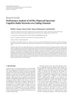
CDMA system depicted in Figure 1 is considered. The system
has K active users, with each kth user’s data b
k
,ofduration
T
b
, being first encoded by a rate r = 1/3turboencoder
resulting in coded bits d
k
.
The coded symbols are then passed through the channel
interleaver. All the interleaved data is demultiplexed by the
space-time demultiplexer (ST-Demux), into substreams. For
the kth user, the demultiplexed symbols are then spread
before transmission using that user’s spreading sequence c
k
of duration T
c
. All substreams are BPSK modulated.
Each user transmits its substream through n
T
transmit
antennas. The transmitted data per symbol time can be
described as
d
=
d
1
, d
2
, , d
K
,(1)
where
d
k
=
d
1
k
, d
2
k
, , d
n
T
k
. (2)
Each transmit antenna, m, has an average transmitter power
of (B
m
k
)
2
, where (B
k
)
2
is the kth user’s overall average power.
It is assumed that all transmit antennas have equal transmit
power of
B
m
k
=
B
k
√
n
R
. (3)
All the n
T
transmitted data streams for all K users
are combined during the wireless transmission process.
A synchronous Rayleigh flat fading uplink MIMO-CDMA
channel is considered.
3. MMSE SPACE-TIME RECEIVERS FOR
CODED MIMO-CDMA SYSTEMS
The received signal on the ηth receiver antenna is given by
r
η
(t) =
K
k=1
n
T
m=1
c
k
(t)H
η,m
k
B
m
k
d
m
k
+ n
η
(t), (4)
where c
k
(t) is the kth user’s spreading sequence, and n
η
(t)is
the AWGN on the ηth receiver antenna.
Here, H
η,m
k
represents the fading factor from the kth
user’s mth antenna to the ηth receiver antenna. To facilitate
the expressing of (4) in discrete-form, we express H as
a Kn
R
× Kn
T
diagonal matrix whose elements are the
submatrix H
k
:
H
= diag
H
1
, H
2
, , H
K
,
(5)
H
k
=
⎡
⎢
⎢
⎢
⎢
⎢
⎢
⎣
H
1,1
k
H
1,2
k
··· H
1,n
T
k
H
2,1
k
H
2,2
k
··· H
2,n
T
k
.
.
.
.
.
.
.
.
.
.
.
.
H
n
R
,1
k
H
n
R
,2
k
··· H
n
R
,n
T
k
⎤
⎥
⎥
⎥
⎥
⎥
⎥
⎦
. (6)
The MIMO-CDMA spreading matrix can be represented
by a Nn
R
×Nn
R
matrix as
C
=
C
1
, C
2
, , C
K
,(7)
D.B.MashwamaandE.O.Bejide 3
b
1
b
K
d
1
d
K
Π
Π
ST-demux
ST-demux
Tur bo
encoder
Tur bo
encoder
d
1
1
d
2
1
.
.
.
d
n
T
1
d
1
K
d
2
K
.
.
.
d
n
T
K
c
1
(t)
c
K
(t)
1
2
n
T
.
.
.
1
2
n
T
.
.
.
n
1
n
2
n
n
R
r
1
r
2
r
n
R
.
.
.
Turbo space-time
multi-user receiver
Figure 1: Turbo space-time coded MIMO-CDMA system.
where
C
k
=
c
1
k
, c
n
k
, , c
N
k
, n ∈{1, 2, , N},
c
n
k
= diag
c
n
k
, c
n
k
, , c
n
k
n
R
.
(8)
Furthermore, the MIMO-CDMA amplitude matrix can
be represented by a Kn
T
×Kn
T
matrix as
B
= diag
B
1
, B
2
, , B
K
,(9)
where
B
k
= diag
B
k
√
n
R
,
B
k
√
n
R
, ,
B
k
√
n
R
n
T
. (10)
The discrete-time representation of the received signal is
expressed in the conventional matrix form as
r
= CHBd + n. (11)
Each of the n
R
receiver antennas is responsible for
the capturing of the transmitted signals from the fading
channel. The received signals are combined and dispread
by a bank of matched filters (MFs). The bank of MIMO
MF will be matched to the corresponding user’s signature
waveform and also to the fading factors of all receiver
antennas. The maximum-ratio combining (MRC) technique
is used to combine all the MF outputs. This combining
and dispreading process will be repeated for all n
T
transmit
antennas.
The MIMO MF output is written as
y
MF
= BH
H
C
T
r = BH
H
RHBd + z, (12)
where H, C,andB are given by (5), (7), and (9), respectively,
R
= CC
T
=
R
k,j
, k, j ∈ [1, 2, , K],
R
k, j
= diag
ρ
k, j
, ρ
k, j
, , ρ
k, j
n
R
,
(13)
where
y
MF
=
y
MF
1
, y
MF
2
, , y
MF
K
T
,
(14)
y
MF
k
=
y
MF,1
k
, y
MF,2
k
, , y
MF,n
T
k
T
,
(15)
z
= BH
H
C
T
n.
(16)
In (15), y
MF,m
k
represents the kth user’s MF output for the
signal received from transmit antenna m given by
y
MF,m
k
= B
m
k
χ
m,m
k,k
d
m
k
+
K
j=0
j
/
=k
B
k
B
j
n
R
χ
m,i
k, j
d
i
j
+ B
m
k
n
m
. (17)
The correlation between the kth and jth user is
χ
k, j
=
⎡
⎢
⎢
⎢
⎢
⎢
⎢
⎣
χ
1,1
k, j
χ
1,2
k, j
··· χ
1,n
T
k, j
χ
2,1
k, j
χ
2,2
k, j
··· χ
2,n
T
k, j
.
.
.
.
.
.
.
.
.
.
.
.
χ
n
T
,1
k, j
χ
n
T
,2
k, j
··· χ
n
T
,n
T
k, j
⎤
⎥
⎥
⎥
⎥
⎥
⎥
⎦
. (18)
From (12), the combined correlation matrix can be expressed
as
χ
= H
H
RH. (19)
The MF output signals, y
MF
, are fed into the MMSE
multiuser antenna to suppress the MAI. The output of the
MMSE multiuser-antenna detector is given by
y
MMSE
=
BχB + σ
2
I
−1
BHCr,
y
MMSE
=
y
MMSE
1
, y
MMSE
2
, , y
MMSE
K
T
,
y
MMSE
1
=
y
MMSE,1
k
, y
MMSE,2
k
, , y
MMSE,n
T
k
T
,
(20)
where I is a Kn
T
×Kn
T
identity matrix.
The soft decision of the MMSE detector outputs is
multiplexed by the space-time multiplexer (ST-Mux). The
4 EURASIP Journal on Wireless Communications and Networking
r
MIMO-MF
y
MF,1
1
y
MF,2
1
y
MF,n
T
1
.
.
.
y
MF,1
2
y
MF,2
2
y
MF,n
T
2
.
.
.
y
MF,1
K
y
MF,2
K
y
MF,n
T
K
.
.
.
MMSE detector
y
MMSE,1
1
y
MMSE,2
1
y
MMSE,n
T
1
.
.
.
y
MMSE,1
2
y
MMSE,2
2
y
MMSE,n
T
2
.
.
.
y
MMSE,1
K
y
MMSE,2
K
y
MMSE,n
T
K
.
.
.
1st PIC stage
y
PIC,1
1,1
y
PIC,1
1,2
y
PIC,1
1,n
T
.
.
.
y
PIC,1
2,1
y
PIC,1
2,2
y
PIC,1
2,n
T
.
.
.
y
PIC,1
K,1
y
PIC,1
K,2
y
PIC,1
K,n
T
.
.
.
pth PIC stage
y
PIC,p
1,1
y
PIC,p
1,2
y
PIC,p
1,n
T
.
.
.
y
PIC,p
2,1
y
PIC,p
2,2
y
PIC,p
2,n
T
.
.
.
y
PIC,p
K,1
y
PIC,p
K,2
y
PIC,p
K,n
T
.
.
.
ST-mux
ST-mux
ST-mux
y
PIC,p
1
y
PIC,p
2
y
PIC,p
K
α
1
1
α
1
2
α
1
K
α
p
1
α
p
2
α
p
K
b
1
b
2
b
K
Π
Π
Π
TD
1
TD
1
TD
1
TD
p
TD
p
TD
p
DD
DD
DD
Figure 2: MMSE front-end turbo space-time PA receiver structure.
multiplexed signal y
MMSE
k
is then deinterleaved before it is
decoded by the turbo decoder. Here, p decoder iterations may
be performed before a hard decision is taken on the turbo
decoder output. However, the focus of this work is the use
of the MMSE space-time receiver in a turbo PIC receiver
configuration.
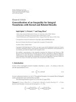
3.1. MMSE front-end turbo space-time
partitioned approach receiver
The MMSE front-end turbo space-time PA receiver for the
MIMO-CDMA system is shown in Figure 2.
The outputs of the MMSE receiver are passed onto
the PIC detector where p IC stages are performed on the
multiplexed MMSE output signals y
MMSE
k
.Afterp IC stages,
the signals y
PIC,p
k,m
are then multiplexed by the ST-Mux before
being deinterleaved.
The PIC detection output after multiplexing is given by
y
PIC,p
= y
MMSE
−
χ −diag[χ]
y
PIC,(p−1)
, (21)
where
y
PIC,p
=
y
PIC,p
1
, y
PIC,p
2
, , y
PIC,p
K
T
,
y
PIC,p
k
=
y
PIC,p
k,1
, y
PIC,p
k,2
, , y
PIC,p
k,n
T
T
.
(22)
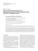
3.2. MMSE front-end turbo space-time
iterative approach receiver
The MMSE front-end turbo space-time IA receiver structure
is shown in Figure 3.
The PIC estimates the signal interference present on the
received signal by reconstructing it from the data estimates
d
i
j
and the cross-correlation values χ
m,i
k, j
and removing it from
the MMSE output signal (note: on the first iteration there
will be no reconstructed estimates of the signal interference).
TheoutputofthePICdetectionprocessisgivenby
y
PIC
= y
MMSE
−B
χ −diag[χ]
B
d, (23)
where
y
PIC
=
y
PIC
1
, y
PIC
2
, , y
PIC
K
T
,
y
PIC
k
=
y
PIC
k,1
, y
PIC
k,2
, , y
PIC
k,n
T
T
.
(24)
The resultant signal y
PIC
is expected to be improved,
after the reconstructed interference is subtracted from the
y
MMSE
signal. This signal is multiplexed and fed into the
turbo decoder. A soft decision is taken on the decoded signal
(which consists of both information and parity LLR values).
These data estimates are demultiplexed by the ST-Demux to
recover the space-time MIMO-CDMA form.
These demultiplexed data estimates are used in the MAI
reconstruction process. The reconstructed interference is
subtracted from the y
MMSE
signal on the next iteration. This
iterative process is repeated for p iterations.
4. TURBO SPACE-TIME RECEIVERS WITH RATE
COMPATIBLE PUNCTURED TURBO (RCPT) CODES
The RCPT encoder will turbo encode the input data sequence
of length L
in
into a coded sequence of length L
out
. The length
of the coded sequence L
out
depends on whether the zero
termination bits, (tail-bits) used for trellis termination, are
included or not. L
out
is given as
L
out
= 3
L
in
+[v − 1]
,
(25)
L
out
= 3L
in
,
(26)
where (25) considers the presence of the tail-bits, while
(26) does not. It is apparent that the transmission of the
tail-bits results in reduced throughput, but we will include
D.B.MashwamaandE.O.Bejide 5
Reconstructed interference
r
MIMO-MF
y
MF,1
1
y
MF,2
1
y
MF,n
T
1
.
.
.
y
MF,1
2
y
MF,2
2
y
MF,n
T
2
.
.
.
y
MF,1
K
y
MF,2
K
y
MF,n
T
K
.
.
.
MMSE detector
y
MMSE,1
1
y
MMSE,2
1
y
MMSE,n
T
1
y
MMSE,1
2
y
MMSE,2
2
y
MMSE,n
T
2
y
MMSE,1
K
y
MMSE,2
K
y
MMSE,n
T
K
.
.
.
y
PIC
1,1
y
PIC
1,2
y
PIC
1,n
T
.
.
.
y
PIC
2,1
y
PIC
2,2
y
PIC
2,n
T
.
.
.
y
PIC
K,1
y
PIC
K,2
y
PIC
K,n
T
.
.
.
ST-mux
ST-mux
ST-mux
y
PIC,p
1
y
PIC,p
2
y
PIC,p
K
Π
Π
Π
TD
TD
TD
α
1
α
2
α
K
DD
HDD
DD
HDD
DD
HDD
b
1
b
2
b
k
b
1
b
2
b
k
ST-demux
ST-demux
ST-demux
b
1
1
b
2
1
b
n
T
1
.
.
.
b
1
2
b
2
2
b
n
T
2
.
.
.
b
1
K
b
2
K
b
n
T
K
.
.
.
MAI reconstruction
.
.
.
.
.
.
.
.
.
Figure 3: MMSE front-end turbo space-time IA receiver structure.
them in this paper since excluding them in the transmission
can result in degradation in the MAP decoder performance
and/or increased delay in iterative decoding [23].
For a r
= 1/M parent encoder, a family of higher rate
codes given by
R
l
=
P
P + l
, l
∈
0, 1, ,(M −1)P
, (27)
where P is called the puncturing period. These are con-
structed by employing a M
×P puncturing matrix P
M
(l). This
matrix indicates the number of subblocks to be transmitted.
An entry of 1 in P
M
(l) indicates a column to be transmitted,
where the first row of P
M
(l) refers to the systematic matrix
and the subsequent rows (i.e., 2 to M) refer to parity matrix
from constituent encoders, RSC1 to RSC (M
− 1). We
consider an example of a rate 1/3turboencoderwithtwo
rate 1/2 RSC encoders and a puncturing period P
= 4:
P
M
(2) =
⎛
⎜
⎝
1111
0010
1000
⎞
⎟
⎠
. (28)
From the first row of P
M
(2), we note that all P = 4
columns of systematic bits are sent. From the second row,
only the third column of RSC1’s parity bits is sent and from
the last row, only the first column of RSC2’s parity bits is sent.
The reader is referred to [23] for a complete list of possible
puncturing tables for different turbo code generators, and
their derivation.
The optimal puncturing tables with puncturing period
P
= 8,givenin[24, Table IV], are used to achieve the higher
order code rates.
If no parity symbols have been received for two or more
RSC encoders, then iterative decoding will not be possible as
the corresponding decoders will be excluded in the iterative
process [23]. In order to take advantage of the iterative MAP
decoders, more parity symbols will be transmitted, and the
possibility of puncturing some of the systematic symbols
arises [24].
5. NUMERICAL RESULTS
In this section, we consider the simulated performance
of a synchronous turbo coded DS-CDMA system that
employs an MMSE front-end turbo space-time multiuser
detector at reception. The communication model considered
consists of K active users that transmit simultaneously and
synchronously through a Rayleigh fading channel. Monte
Carlo simulations are used to obtain the performance of the
turbo receivers. The receivers all assume perfect knowledge
of the channel state information. The maximum number of
active system users is K
= 15, and each user transmits an
information frame size of L
in
= 1024 data bits. The FEC code
used is a rate r
= 1/3 turbo code with a component encoder
with generator polynomial (7, 5)
octal
. All spreading codes are
of length N
= 15 and are generated in a pseudorandom
manner for each user.
The uplink of the above system is considered with a
maximum of 2 transmit antennas at the mobile station and a
maximum of 2 receive antennas at the base station.
5.1. Comparison on simulated nonpunctured PA and
IA receiver pe rformances
For each approach, we perform four iterative cancellation
stages (or joint cancellation stages in the case of IA) thus
giving a fair comparison, in terms of complexity, between the
two systems as both are viewed to perform the same number
of floating point operations per user per symbol, however in-
depth complexity issues are not discussed in this paper.
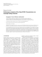
Figure 4 shows the performance comparison of the PA
and IA receivers over four receiver iterations for a system with
6 EURASIP Journal on Wireless Communications and Networking
BER
1E +00
1E
−01
1E
−02
1E
−03
1E
−04
1E
−05
SNR (dB)
012345
PA, 1
×1
IA, 2
×2
IA, 1
×1
PA, 2
×2
Figure 4: Performance of PA and IA schemes as a function of BER
per SNR for a system with 5 active users.
BER
1E +00
1E
−01
1E
−02
1E
−03
1E
−04
1E
−05
1E
−06
Users
0 5 10 15
PA
IA
Figure 5: IA and PA system capacity comparison for a 2 ×2system
configuration at SNR
= 2dB.
K = 5 users. The results show that the IA achieves marginal
gains in 4 iterations and reaches a BER of 10
−3
at SNR of
1.4 dB while the PA receiver maintains the same performance
at an SNR value of 1.6 dB for the 2
×2 diversity system. The IA
advantage in terms of capacity for low-loaded systems seems
to be very marginal. This observation holds even for the case
of a no diversity system.
However as the system load increases, the performance
gains of the IA receiver become more obvious as indicated in
Figure 5. This graph shows the capacity performance of both
IA and PA receivers in a 2
×2 diversity system configuration
evaluated over four receiver iterations. Depending on the
diversity configuration employed, it can be noted that the IA
receiver maintains a considerable capacity gain over the PA
BER
1E +00
1E
−01
1E
−02
1E
−03
1E
−04
1E
−05
Iterations
1234
Single user
IA, 5 users
IA, 15 users
PA, 5 users
PA, 15 users
Figure 6: Performance of PA and IA schemes as a function of BER
per iteration for a 2
×2 diversity system at SNR = 4dB.
receiver for a BER performance of 10
−3
at an SNR value of
2 dB for this diversity system configuration.
A more in-depth look into the performance of both PA
and IA receivers as a function of the number of iterations
is shown in Figure 6. Worth noting are the observations
made from Figure 6 for highly loaded systems: the PA
receiver reaches an error floor just under a BER of 10
−1
,
and no amount of additional iterations can improve the
performance of this receiver. In contrast, a highly loaded
system performance of the IA receiver reveals that more
performance improvement is attainable with an increase in
the number of iterations.
5.2. Comparison on simulated punctured PA and
IA receiver pe rformances
In this section, we investigate the RCPTC scheme based on
arater
= 1/3 mother code for a Rayleigh fading channel
model. The data bits of each user for the rate r
= 1/3
encoder are assigned according to puncturing [24, Table IV]
with puncturing period P
= 8. For performance evaluation
purposes, we consider values of l
= 2,8, and 16 thus giving
rates r
= 4/5, 1/2, and 1/3, respectively. These code rates are
adopted for the PA and IA receivers. Since full rate space-
time block codes are being used, the overall code rate of
both systems is not affected, thus the puncturing pattern
used determines the total system code rate. Furthermore, we
assume that the effects of puncturing on the overall system
complexity are negligible. This assumption can be quantified
by reasoning that puncturing merely involves the removal of
a subset of the encoded bits at transmission and the addition
of dummy bits at the receiver end.
Simulations were conducted to investigate the degree
of performance degradation due to the implementation of
punctured rates r
= 4/5andr = 1/2 for a single user system
D.B.MashwamaandE.O.Bejide 7
BER
1E +00
1E
−01
1E
−02
1E
−03
1E
−04
SNR (dB)
0246810
K
= 1, r = 1/3, 2 ×2
r
= 1/3, 1 ×1
r
= 1/2, 1 ×1
r
= 4/5, 1 ×1
r
= 1/3, 2 ×2
r
= 1/2, 2 ×2
r
= 4/5, 2 ×2
Figure 7: BER versus SNR performance graph for punctured K = 5
users IA system with diversity.
BER
1E +00
1E
−01
1E
−02
1E
−03
1E
−04
SNR (dB)
0246810
K = 1, r = 1/3, 2 ×2
r
= 1/3, 1 ×1
r
= 1/2, 1 ×1
r
= 4/5, 1 ×1
r
= 1/3, 2 ×2
r
= 1/2, 2 ×2
r
= 4/5, 2 ×2
Figure 8: BER versus SNR performance graph for punctured K =
15 users IA system with diversity.
with no diversity and also a 2×2 diversity system both which
are bench-marked against the rate r
= 1/3equivalentsystem.
Figures 7 and 8 show the punctured IA receiver BER
versus SNR performance graphs for the K
= 5andK = 15
user systems, respectively. Simulations are considered for a
synchronous system with N
= 15 for both nondiversity and
2
× 2 diversity turbo coded systems employing an iterative
approach detection scheme at reception.
In both graphs, there is expected system degradation
due to MAI. The higher code rate shows a further loss in
performance for both the K
= 5andK = 15 systems.
BER
1E +00
1E
−01
1E
−02
1E
−03
1E
−04
Code rate, r
0.30.40.50.60.70.80.91
K
= 5, 1 ×1
K
= 5, 2 ×2
K
= 1, 1 ×1
K
= 1, 2 ×2
K
= 15, 1 ×1
K
= 15, 2 ×2
Figure 9: Punctured multiple user BER performance as a function
ofthecoderateatSNR
= 2dBforPAreceiver.
BER
1E +00
1E
−01
1E
−02
1E
−03
1E
−04
Code rate, r
0.30.40.50.60.70.80.91
K
= 5, 1 × 1
K
= 5, 2 × 2
K
= 1, 1 × 1
K
= 1, 2 ×2
K
= 15, 1 ×1
K
= 15, 2 ×2
Figure 10: Punctured multiple user BER performance as a function
ofthecoderateatSNR
= 2dBforIAreceiver.
The effects of increasing the system capacity coupled with
an increase in the system code rate can be better observed in
Figure 9 for the PA system and Figure 10 for the IA system.
Figure 9 shows punctured BER performance as a func-
tion of the code rate at SNR
= 2dB for PA receiver with
system loads of K
= 5andK = 15. The single user
performance graphs for both the nondiversity and 2
× 2
diversity systems are also given for comparison reasons.
From Figure 9, it is clear that at such a low SNR value, the
multiple user systems fail to reach the 10
−3
BER performance
threshold for both nondiversity and 2
× 2 diversity systems.
8 EURASIP Journal on Wireless Communications and Networking
This poor performance can, however, be attributed to the
choice of receiver used.
Figure 10 illustrates the simulated punctured multiuser
BER performance as a function of the code rate at SNR
=
2dBforanIAreceiver.
From Figure 10, it is observed that the nondiversity
systems for all system loading values perform similarly to
that of the PA receiver and fail to achieve the performance
threshold. However as the diversity is increased to 2
× 2,
the IA system performs much better than the PA system and
attains the performance threshold at a code rates of r
= 0.39
and r
= 0.32 for the K = 5andK = 15 systems, respectively.
6. CONCLUSION
In this paper, two turbo interference cancellation receivers
are discussed and are divided into the MMSE front-end
turbo space-time partitioned approach receiver (PA) and
the MMSE front-end turbo space-time iterative approach
receiver (IA). Numerical results reveal that for an equal
number of receiver iterations both IA and PA receivers
achieve approximately the same performance for a lightly
loaded system at any given performance threshold. However
as the system load increases, the IA starts to gain sizable per-
formance and capacity gains over the PA receiver. Important
to note is that the PA receiver (as compared to the IA receiver)
is seen to attain no further performance or capacity gains
with an increased number of iterations for the case of a highly
loaded system. This poor PA performance can possibly be
attributed to the poor parity data decoding performance
characteristic of turbo codes.
Rate compatible punctured turbo codes are investigated
in a turbo space-time coded MIMO-CDMA system as a
possible way of achieving higher data rates in DS-CDMA
uplink. Results show that by using two transmitting antennas
and two receiving antennas, there is a higher attainable data
rate when compared with the nondiversity system. There is,
however, a limit to the degree of puncturing that can be
done, this limit is generally dictated by the required system
performance threshold.
With an increase in SNR, the stipulated system perfor-
mance can even be attained by using higher code rates, thus
significantly increasing the achievable data rates. However,
it is observed that as the system load increases the degree
of freedom on puncturing becomes greatly reduced. This
is attributed to the choice of receiver being employed at
reception. The IA receiver is observed to be a better receiver
choice than the PA receiver when considering the achievable
data rates in a heavily loaded CDMA system.
ACKNOWLEDGMENTS
This work was supported in part by the South Africa’s
National Research Foundation. D. B. Mashwama and E.O.
Bejide are with the Department of Electrical Engineering,
University of Cape Town, Private Bag, Rondebosch 7701,
South Africa.
REFERENCES
[1] S. Verd
´
u, Multiuser Detection, Cambridge University Press,
Cambridge, UK, 1998.
[2] S. Moshavi, “Multi-user detection for DS-CDMA communi-
cations,” IEEE Communications Magazine, vol. 34, no. 10, pp.
124–135, 1996.
[3] A. Duel-Hallen, J. Holtzman, and Z. Zvonar, “Multiuser
detection for CDMA systems,” IEEE Personal Communications,
vol. 2, no. 2, pp. 46–58, 1995.
[4] G. J. Foschini and M. J. Gans, “On limits of wireless com-
munications in a fading environment when using multiple
antennas,” Wireless Personal Communications,vol.6,no.3,pp.
311–335, 1998.
[5] V. Tarokh, H. Jafarkhani, and A. R. Calderbank, “Space-time
block codes from orthogonal designs,” IEEE Transactions on
Information Theory, vol. 45, no. 5, pp. 1456–1467, 1999.
[6] T. R. Giallorenzi and S. G. Wilson, “Multiuser ML sequence
estimator for convolutionally coded asynchronous DS-CDNA
systems,” IEEE Transactions on Communications,vol.44,no.8,
pp. 997–1008, 1996.
[7] T. R. Giallorenzi and S. G. Wilson, “Suboptimum multiuser
receivers for convolutionally coded asynchronous DS-CDMA
systems,” IEEE Transactions on Communications,vol.44,no.9,
pp. 1183–1196, 1996.
[8]P.D.Alexander,M.C.Reed,J.A.Asenstorfer,andC.B.
Schlegel, “Iterative multiuser interference reduction: turbo
CDMA,” IEEE Transactions on Communications, vol. 47, no.
7, pp. 1008–1014, 1999.
[9] C. Berrou, A. Glavieux, and P. Thitimajshima, “Near Shannon
limit error-correcting coding and decoding: turbo-codes,” in
Proceedings of the IEEE International Conference on Communi-
cations (ICC ’93), vol. 2, pp. 1064–1070, Geneva, Switzerland,
May 1993.
[10] A. R. Muller and B. J. Huber, “Iterated soft decision
interference cancellation for CDMA,” in Broadband Wireless
Communications, M. Luise and S. Pupolin, Eds., Springer,
London, UK, 1998.
[11] H. El Gamal and E. Geraniotis, “Iterative multiuser detection
for coded CDMA signals in AWGN and fading channels,” IEEE
Journal on Selected Areas in Communications,vol.18,no.1,
pp. 30–41, 2000.
[12] J M. Hsu and C L. Wang, “A low-complexity iterative
multiuser receiver for turbo-coded DS-CDMA systems,” IEEE
Journal on Selected Areas in Communications,vol.19,no.9,
pp. 1775–1783, 2001.
[13] E. O. Bejide and F. Takawira, “An iterative multiuser detector
for turbo-coded DS-CDMA systems,” EURASIP Journal on
Applied Signal Processing, vol. 2005, no. 6, pp. 883–891, 2005.
[14] J. Shen and A. G. Burr, “Turbo multiuser receiver for space-
time turbo coded uplink CDMA over frequency-selective
fading channel,” in Proceedings of the 5th European Personal
Mobile Communications Conference, pp. 357–361, Glasgow,
UK, April 2003.
[15] R. Kohno, H. Imai, M. Hatori, and S. Pasupathy, “Combina-
tions of an adaptive array antenna and a canceller of inter-
ference for direct-sequence spread-spectrum multiple-access
system,” IEEE Journal on Selected Areas in Communications,
vol. 8, no. 4, pp. 675–682, 1990.
[16] S. Y. Miller and S. C. Schwartz, “Integrated spatial-temporal
detectors for asynchronous Gaussian multiple-access chan-
nels,”IEEE Transactions on Communications, vol. 43, no. 234,
pp. 396–411, 1995.
D.B.MashwamaandE.O.Bejide 9
[17] X. Wang and H. V. Poor, “Space-time multiuser detection
in multipath CDMA channels,” IEEE Transactions on Signal
Processing, vol. 47, no. 9, pp. 2356–2374, 1999.
[18] M. C. Reed and P. D. Alexander, “Iterative multiuser detection
using antenna arrays and FEC on multipath channels,” IEEE
Journal on Selected Areas in Communications, vol. 17, no. 12,
pp. 2082–2089, 1999.
[19] J. Thomas and E. Geraniotis, “Soft iterative multisensor mul-
tiuser detection in coded dispersive CDMA wireless channels,”
IEEE Journal on Selected Areas in Communications, vol. 19, no.
7, pp. 1334–1351, 2001.
[20] W. Hamouda and P. McLane, “Performance analysis of space-
time MMSE multiuser detection for coded DS-CDMA systems
in multipath fading channels,” IEEE Transactions on Wireless
Communications, vol. 5, no. 4, pp. 829–838, 2006.
[21] D. B. Mashwama and E. O. Bejide, “Turbo space-time
multiuser detection for DS-CDMA systems in Rayleigh fading
channels,” in Proceedings of Southern African Telecommunica-
tion Networks & Applications Conference (SATNAC ’07),Sugar
Beach Resort, Mauritius, September 2007.
[22] D. B. Mashwama and E. O. Bejide, “Turbo multi-user
detection in AWGN CDMA systems,” submitted to Research
Letters in Communications.
[23] D. N. Rowitch and L. B. Milstein, “Rate compatible punctured
turbo (RCPT) codes in a hybrid FEC/ARQ system,” in Pro-
ceedings of IEEE Communication Theory Mini-Conference in
Conjunction with IEEE Global Telecommunications Conference,
vol. 4, pp. 55–59, Phoenix, Ariz, USA, November 1997.
[24] D. N. Rowitch and L. B. Milstein, “On the performance of
hybrid FEC/ARQ systems using rate compatible punctured
turbo (RCPT) codes,” IEEE Transactions on Communications,
vol. 48, no. 6, pp. 948–959, 2000.