Báo cáo hóa học: "Research Article Dynamic Resource Assignment and Cooperative Relaying in Cellular Networks: Concept and Performance Assessment" pot
Bạn đang xem bản rút gọn của tài liệu. Xem và tải ngay bản đầy đủ của tài liệu tại đây (1.22 MB, 14 trang )
Hindawi Publishing Corporation
EURASIP Journal on Wireless Communications and Networking
Volume 2009, Article ID 475281, 14 pages
doi:10.1155/2009/475281
Research Article
Dynamic Resource Assignment and Cooperative Relaying in
Cellular Networks: Concept and Performance Assessment
Klaus Doppler,
1
Simone Redana,
2
Michał W
´
odczak,
3
Peter Rost,
4
and Risto Wichman
5
1
Radio Communication CTC, Nokia Research Center, It
¨
amerenkatu 11-13, 00180 Helsinki, Finland
2
Radio Systems, Research & Technology, Research, Technology and Platforms, Nokia Siemens Networks GmbH & Co. KG,
St. Martin Strasse 76, 81541 Munich, Germany
3
Applied Research, Telcordia Technolog ies, Telcordia Poland Sp. z o.o., ul. Umultowska 85, 61-614 Pozna
´
n, Poland
4
Vodafone Chair Mobile Communications Systems, Technical University of Denmark, Helmholtzstr. 10, 01069 Dresden, Germany
5
Department of Signal Processing and Acoustics, Helsinki Unive rsity of Technology, P.O. Box 3000, 02015 TKK, Finland
Correspondence should be addressed to Klaus Doppler,
Received 18 February 2009; Revised 19 May 2009; Accepted 1 July 2009
Recommended by Mischa Dohler
Relays are a cost-efficient way to extend or distribute high data rate coverage more evenly in next generation cellular networks.
This paper introduces a radio resource management solution based on dynamic and flexible resource assignment and cooperative
relaying as key technologies to enhance the downlink performance of relay-based OFDMA cellular networks. It is illustrated how
the dynamic resource assignment is combined with beamforming in a macrocellular deployment and with soft-frequency reuse
in a metropolitan area deployment. The cooperative relaying solution allows multiple radio access points to cooperatively serve
mobile stations by combining their antennas and using the multiantenna techniques available in the system. The proposed schemes
are compared to BS only deployments in test scenarios, which have been defined in the WINNER project to be representative for
next generation networks. The test scenarios are well defined and motivated and can serve as reference scenarios in standardisation
and research. The results show that the proposed schemes increase the average cell throughput and more importantly the number
of users with low throughput is greatly reduced.
Copyright © 2009 Klaus Doppler et al. This is an open access article distributed under the Creative Commons Attribution License,
which permits unrestricted use, distribution, and reproduction in any medium, provided the original work is properly cited.
1. Introduction
Mobile users in next generation communication systems
are expecting seamless coverage with a guaranteed Quality
of Service (QoS) to allow for a similar user experience as
provided by today’s broadband internet connections. This
causes a high spectrum demand of approximately 100 MHz
to support high aggregate data rates of up to 1 Gbit/s, which
will only be available at frequencies higher than 2 GHz. The
World Radio Conference 2007 has, for example, identified
200 MHz at 3.4 GHz for IMT systems. The high bandwidth
and carrier frequencies together with regulatory constraints
on the transmission power will limit the range for broadband
services. Thus, many small cells are required for contiguous
coverage of areas with high traffic density.
In-band relays are seen as a cost efficient way to extend
the high throughput coverage of next generation mobile
networks. In [1] it was shown that deployments based on in-
band relays can increase the high bit rate coverage at the cell
border; thereby providing the means to balance the capacity
within the cell and increase the coverage area. Relays as part
of infrastructure based networks are currently standardised
in the Technical Specification Group j (TSG j) of IEEE802.16
[2] and it is currently a study item in 3 GPP [3].
The main focus of this paper is on the performance
gain in the downlink of cellular relay networks compared
to base station (BS) only deployments in test scenarios
that are foreseen for next generation cellular networks. We
propose two key radio resource management techniques to
exploit the full potential of relay enhanced cellular OFDMA
networks: dynamic and flexible resource assignment in
a relay enhanced cell and cooperative relaying. We have
developed these techniques during five years (2003–2008)
of extensive research on cellular relay networks within
2 EURASIP Journal on Wireless Communications and Networking
the European research project WINNER [4]. The dynamic
resource assignment adapts to changing user and traffic
densities and it is flexible enough to be applicable to
deployment scenarios ranging from wide area deployments
to local area office deployments. In particular we show
how to adapt the dynamic resource assignment to a wide
area deployment which utilizes a grid of beams at the
base station and to a metropolitan area network utilizing
soft-frequency reuse for interference coordination. Our
cooperative relaying proposal allows the cooperating radio
access points (base station or relay station) to utilize any
multiantenna technique used by the system to jointly serve
users.
We present numerical evaluation results on the achiev-
able downlink gains from dynamic resource assignment and
cooperative relaying compared to BS-based deployments.
The numerical results show the final assessment results in
a wide area, a metropolitan area, and indoor test scenarios.
The results are based on an extensive set of system level
simulations after several iterations and refinements during
the course of the last three years. Next to the results we
describe and motivate the used relay deployments in a wide
area, metropolitan area, and an indoor test scenario. We have
defined these relay test scenarios in WINNER and they have
been contributed to the guidelines by ITU-R for evaluating
candidate radio interface technologies for IMT-Advanced
[5].
The remainder of this paper is organized as follows. In
Section 2 we give an overview on related work. In Section 3
we present the test scenarios for a metropolitan area
(Manhattan grid), a wide area (hexagonal grid), and a local
area (office environment) relay deployment. In Section 4,
we outline the proposed dynamic resource assignment for
relay enhanced cells and illustrate its application to the
test scenarios. Further, we discuss different flow control
mechanisms and introduce our cooperative relaying concept
as an add-on to single-path relaying. Thereafter, we present
in Section 5 the performance assessment results obtained by
system level simulations for the proposed dynamic resource
assignment and cooperative relaying in the aforementioned
test scenarios.
2. Related Work
The main focus of this paper is on the downlink system
performance of a cellular relay network. There is few related
work in this area and the results have been obtained with
very different assumptions, that is, they are typically not
directly comparable. Some of the results where obtained for
relaying scenarios where the relay station (RS) transforms a
non-line-of-sight (NLOS) base station-mobile station (BS-
MS) link into two line-of-sight (LOS) BS-RS and RS-MS
links. The BS-RS links can be planned in a cellular network
for stationary RSs and the probability of an LOS BS-RS link
is increased. However, the MSs can be located anywhere in
the cell and the probability of LOS to the BS should be at
least the same or even higher than to the RS because the BS
is typically deployed higher than the RS. Thus, in order to
enable a fair comparison the properties of the BS-MS and RS-
MS links should only depend on the deployment. In addition
these papers consider all the interfering links to be NLOS,
that is, the resulting Signal-to-Interference and Noise Ratios
(SINRs) for the RS-MS links are too high. In our studies we
did not make such assumptions to ensure a fair comparison.
The downlink performance of a multicell WINNER
network in a wide area scenario has also been studied in
[6]. Under the assumption of an LOS BS-RS and RS-MS
link and NLOS BS-MS and interfering links the saturated
throughput of the relay deployment is 25% higher in the
relay deployment compared to the same deployment without
relays. However, this paper does not apply the dynamic
resource assignment proposed in this paper and thus higher
gains are expected under these assumptions.
The IEEE 802.16j has issued a draft standard [7]andfirst
performance results for the downlink of such a system are
available. In [8] a scenario with 14 RS added to each BS
in a macrocellular deployment with a cell radius of 1 km is
studied. Again an RS transforms an NLOS BS-MS link into
two LOS BS-RS and RS-MS links. Under this assumption
the relay deployment increases the downlink capacity of the
cellular network by more than 100%. The results in [9]
indicate that for relays that do not extend the coverage area
of a BS (transparent relays in IEEE 802.16j) the performance
gains are below 5%. In [10]different reuse pattern and
path selection rules have been studied. The results show
that a macrocellular relay deployment can serve up to 90%
more users than a BS-based deployment. However, this
comparison does not consider sectors at the BS and shadow
fading as well as fast fading is not modeled. Further, the RS
transmission power is only 3 dB less than the BS transmission
power, which would not result in significant cost savings due
to the use of relays.
Another set of assessment results for a WiMAX relay
deployment in a metropolitan area is available in [11, 12].
Unfortunately, there is no comparison with a BS only
deployment but the results show significant gains from using
directive antennas. In this work it is assumed that the BSs
and RNs are deployed at street crossings with directional
antennas covering the streets leading to the crossing. In
practical deployments it will be hard to deploy a radio access
point at street crossings and therefore our work focuses on
a deployment in the streets which is also recommended by
3GPPin[13] and similar to [11, 12] we also utilize directive
antennas (sectors) at the BS. Secondly, the previous work
in the metropolitan area has focused on outdoor users in
the street whereas we consider also users inside the building
blocks that typically account for most of the trafficina
cellular network.
In addition to multicell studies, several aspects of the
cellular downlink of OFDMA systems have been studied
for a single cell. In [14] the OFDMA resource allocation
for a single relay enhanced cell with multiple users and a
maximum C/I scheduler is analyzed. In these studies the
relay deployment achieves 15% higher data throughput and
the outage probability is reduced from 30% to 20%. In [15]
it is shown that the optimization of the subframe duration
(RS transmits to MS/RS receives from BS) together with
EURASIP Journal on Wireless Communications and Networking 3
RRC
RLC
MAC
PHY
RRC
RLC
MAC
PHY
Transp
ort
network
MS GW
I
W
I
BRN
RRC
RLC
MAC
PHY
Transp
ort
network
RS
BS
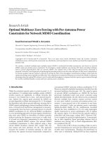
Figure 1: RSs within the cellular network, the control plane.
subcarrier allocation improves the overall cell throughput
compared to subcarrier allocation only as proposed in [16].
These single cell results confirm that the subframe duration
should be flexible as proposed by our dynamic resource
assignment.
System performance results of relay-based deployments
for the cellular uplink for the WINNER system can be found
in [17] and for IEEE 802.16j in [18]. Early performance
assessment results for cellular relay networks that are not
based on OFDMA can be found, for example, in [19] for the
integrated Cellular Ad hoc Relay System, in [20]formobile
relays, and in [21]fora1xEVDOsystemenhancedbyrelays.
The results presented in this paper are the final assess-
ment results of the relay-based system developed in WIN-
NER Phase II [22]. We have presented parts of the concept
and early performance results in [23–27].
Differently to our wide area results in [23] these are the
first results that have been obtained in a dynamic scenario
and we compare the performance of a relay deployment
with dynamic resource sharing to a BS only deployment.
In addition we utilize the connection-based scheduling flow
control scheme that we have presented in the context of
WiMAX in [24]. The results in [26] have been obtained
for relays deployed above rooftop and with more relays per
sector. Increasing the amount of relays increases the benefits
due to cooperative relaying but it also increases the costs of
the deployment.
The metropolitan area results in [25] did not utilize soft-
frequency reuse for the BS only scenario and the power masks
have been updated for the relay scenario considered in this
paper. Further, we utilize the interference aware scheduling
scheme designed for soft-frequency reuse that we evaluated
for a BS only deployment in [28]. This is also the first time
that we present results for outdoor users and show the effect
of a simple flow control on the system performance.
The local area results in [27]compareddifferent relay
deployment options whereas now we compare the expected
user throughput of a relay deployment to a BS only
deployment.
3. Relay Properties and Test Scenarios
The design of a radio resource management scheme for relay-
based systems depends on the properties of the relays and on
the deployment of the relays. In addition the multiantenna
techniques utilized in the system have to be taken into
account. Therefore we introduce and motivate first the main
properties of the relays and the relay deployments considered
in our work. The main motivation to deploy relays is to
save costs while reaching a similar performance as less dense
BS only deployments or to increase the performance of
aBSdeploymentcostefficiently by adding relays. Hence,
most of the following design choices are motivated by cost
considerations.
In our test scenarios we allow an intelligent deployment
with favorable propagation conditions between the base
station (BS) and the relay station (RS), for example, line-
of-sight (LOS) to the BS. As a consequence the quality
of the BS-RS link can be very different from the RS-MS
link. Therefore, we consider only decode-and-forward relays
(operating up to OSI layer 3), which can take advantage of
dynamic resource allocation and adaptive transmissions with
different modulation and coding schemes when receiving
and forwarding data.
The intelligent deployment assumption is based on cost
comparison studies of relay based and BS only deployments.
For intelligent relay deployments studied in [29, 30]RSs
are already cost efficient if the costs are 88% of the costs
of a micro-BS. Without intelligent deployment the RS cost
should be only 6.5% of the BS costs [31].
ThenumberofRSsperBSisanimportantdesign
parameter that affects both the costs and the performance
of the relay network. We have limited the number of RSs to
three per BS sector based on the result curves in [29]which
do not suggest more than 4 RSs per BS in a scenario similar
to the one considered in our work.
To keep the size of RSs small we assume in all scenarios
a limited transmit power for RSs and a maximum of two
antennas. Small RSs that do not require shelter, cooling, and
backhaul connection increase the deployment flexibility and
allow, for example, a deployment on lamp posts. Thereby
the site acquisition and site rental costs can be reduced even
compared to a micro- or pico-BS. According to cost studies in
[32] site rental and the cost of the transmission line account
for more than 60% of the overall costs of a micro-BS over 10
years.
Finally, we require that adding a RS to the network
does not increase the cost of an MS. This is achieved by
a RS that provides an identical interface towards an MS
as a BS, that is, the MS does not need to distinguish
between RS and BS and both are referred to as radio
access points. Further, we focus on in-band relays that do
not require additional bandwidth. The resulting multihop
cellular system architecture is illustrated in Figure 1 [33]. A
Relay Enhanced Cell (REC) is formed out of a BS together
with its associated RSs.
Our test scenarios are primarily designed and optimized
for two hops (BS-RS-MS) in order to achieve a high
performance in terms of throughput and delay. Further, we
assume a tree topology to avoid the overhead from complex
routing protocols. In the rare case of node failure the RS can
autonomously connect itself to another radio access point in
its range.
For base station-based deployments the hexagonal grid
cell layout with variable intersite distance and the Manhattan
grid following the UMTS 30.03 recommendations [13]have
4 EURASIP Journal on Wireless Communications and Networking
been accepted as evaluation scenarios in standardization and
research. However, no such widely accepted scenarios exist
for relay deployments and the results of different research
groups are not comparable.
In the following we present relay test scenarios for
three typical deployments of future wireless communication
systems: a wide area scenario that provides base urban
coverage based on a hexagonal cell layout, a metropolitan
area scenario based on microcells deployed in a Manhattan
grid, and a local area office scenario. Both the wide area
and the metropolitan area scenarios cover the important
case of an operator that wants to upgrade an existing
UMTS network and to reuse the existing BS locations. The
properties of the MS are the same in all scenarios (see Ta bl e 4
in Appendix A).
All three test scenarios use path loss and channel
models developed in Phase II of the WINNER project. The
properties of the channel model and a comparison to other
models can be found in [34]. The path-loss equations and
the corresponding channel models can also be found in [35].
Since [35]offers several possible path-loss models for each
link type we state the path-loss equations used in the test
scenarios in Appendices B, C,andD.
3.1. Wide Area Test Scenario. The wide area test scenario is
an urban macrocellular deployment. It aims at providing
ubiquitous coverage in an urban environment resulting in
rather large cells, having a radius up to several kilometers.
Base stations (BSs) are consequently expected to provide
high power outputs, in each of the three sectors, equipped
with four antennas. All BSs are deployed above rooftop
(h
BS
= 25 m), possibly requiring additional masts for
their installation. This implies that the site selection and
rental costs will probably be dominant with respect to the
other costs such as the backhaul infrastructure. We further
consider RSs which are deployed below rooftop (h
RS
= 5m)
with a single antenna and a significantly lower output power
in order to keep costs low and allow for a flexible deployment
of multiple RSs per sector. For the same reason the RS is
equipped with a single antenna.
We distinguish between a carefully planned RS deploy-
ment with a high probability of line-of-sight (LOS) and a not
carefully planned RS deployment without LOS to the BS. For
both cases and the BS-MS link we assume an urban macro-
cell model whereas we assume for the RS-MS a non-LOS
(NLOS) microcell model (see Appendix B for details).
The cells form a regular grid with a hexagonal layout
and an intersite distance (ISD) of 1000 meters. We study
this scenario with three RSs per sector according to the
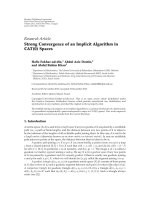
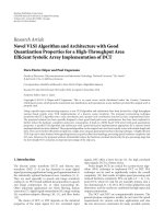
deployment in Tab l e 1. It provides, as shown in Figure 2,
a good coverage for MSs at the cell border. Moreover, we
consider also the scenario with only one RS per sector (also
shown in Figure 2) for comparison purpose. The exact RS
deployments are outlined in Tab le 1 for both scenarios.
3.2. Metropolitan Area Test Scenario. The metropolitan area
test scenario is an urban micro-cellular scenario modeled
by a two-dimensional Manhattan grid consisting of 12
× 12
0 100 200 300 400 500 600 700
−100
0
100
200
300
400
500
x (m)
y (m)
BS
RN
θ
(a) 1RS per sector
0 100 200 300 400 500 600 700
−100
0
100
200
300
400
500
x (m)
y (m)
BS
RN
RN
RN
θ
(b) 3RS per sector
Figure 2: Coverage area for BS and RS in wide area test scenario.
Table 1: RS deployment in the wide area test scenario.
Num RSs BS-RS Θ (deg)
per sector distance (m) (relative to sector broadside direction)
1 440 0
3 500
−24, 0, 24
streets (width 30 m) and 11 × 11 buildings (200 m × 200 m
block size). The BS deployment follows the UMTS 30.03
recommendation [13] with 73 BS deployed below rooftop
level (10 m height) and placed in the midpoint between two
crossroads. Two sectors are formed with bore-sight along the
street direction and one antenna per sector. The added relays
extend the coverage area of these BSs and distribute the cell
capacity more evenly.
EURASIP Journal on Wireless Communications and Networking 5
REC
BS RN
Power masks
[1 0.5 0.25]
[0.5 0.25 1]
[0.25 1 0.5]
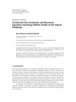
Figure 3: Sketch of metropolitan area cell layout with relay stations
and assigned soft-frequency reuse power masks.
A single RS (5 m height) is added to each BS site in the
midpoint between two BSs, as depicted in Figure 3.Thereby
the number of radio access points is doubled. Adding a
second relay per BS site increases the cell throughput only
slightly and does not justify the additional costs [25]. The
RSs are equipped with two antennas, a directional antenna
to communicate with the serving BS and an omnidirectional
antenna to serve its MSs. The power masks assigned to
each BS and RS in Figure 3 are used by an interference
coordination scheme based on soft-frequency reuse which is
described in Section 4. The transmit power of the RS is 7 dB
lower than the transmit power of the BS to enable a smaller
physical size.
A LOS link is assumed for nodes in the same street and a
NLOS link for nodes in different streets and MSs are located
inside a building or in a street. Details of the propagation
model and additional simulation parameters can be found in
Appendix C.
3.3. Local Area Test Scenario. The local area test scenario
is defined as an isolated hot-spot-like indoor area with
high user density where the users are either stationary or
slowly moving. It is characterized by high shadowing and
considerable signal attenuation due to the existence of rooms
separated by walls. As a result of the isolated characteristics
the interference is much lower compared to the previous two
scenarios. The scenario consists of one floor (3 m high) in
10
20
30
40
10 20 30 40 50 60
70
8090
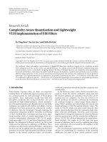
Figure 4: Local area scenario with two BSs (dark gray) and four
relay stations (light gray) to assist each BS.
a building with two corridors (5m × 100 m) and 40 rooms
(10 m
× 10 m).
A deployment with two single antenna BSs (dark gray
nodes) is presented in Figure 4. They are located in the
middle of the corridors, halfway from the left/right side of
the building. Each of them is assisted by four single antenna
RSs (light gray nodes): two on the left and two on the right
side, respectively (i.e., 10, 30, 70, and 90 meters from the
left or the right side of the building) as depicted in Figure 4.
All the area marked with gray color benefits from the use of
(cooperating) RSs.
A LOS or NLOS office propagation model is employed
depending on the presence of walls between the BS, RSs,
and MSs. Details of the propagation model and additional
simulation parameters can be found in Appendix D.
4. Radio Resource Management in
Relay Enhanced Cells
Relays add additional degrees of freedom to the radio
resource management of a cellular system. The RS can
act as a BS to serve its MS or as an MS to receive data
from the BS. The coverage area of an RS is lower than
for a BS due to the lower transmit power and different
deployments. Nevertheless, they should be integrated and
evaluated together with the interference coordination and
multiantenna techniques utilized in the network. On the
other hand the cooperation of multiple radio access points
is easier in a relay enhanced cell than between BSs since the
BS can act as a coordinating node in the resource allocation
for cooperatively served users.
In the following we propose the following radio resource
management techniques for relay enhanced cells: dynamic
resource assignment, flow control for multihop connections
and cooperative relaying as an add-on to single-path relay-
ing.
4.1. Dynamic Resource Assignment. A fixed and static
resource assignment will not allow to exploit the full poten-
tial of relay-based deployments since the relay deployments
can have very different properties as illustrated in Section 3.
Therefore, we propose that the BS flexibly assigns parts or
all of the available system resources to itself and to each RS
6 EURASIP Journal on Wireless Communications and Networking
in the relay enhanced cell. In particular the BS assigns the
frames in which the RS communicates with the BS (act as
an MS) or serves its MS (act as a BS). Further, it assigns the
OFDMA resource units (chunks) that the RS can use in the
frames for which it acts as a BS. The assigned resources are
then available for autonomous scheduling at each individual
radio access point. Figure 5 illustrates an example resource
allocation for a BS with three RS in its cell.
The actual resource assignment strategy depends on
the utilized interference coordination and multiantenna
techniques. In the wide area test scenario beamforming has
been shown to be an effective way to improve the cell capacity
[37]. We propose to coordinate the interference from the
subcells formed by the BS to the subcell formed by RSs
by using at the BS beams with low interference to the RS
subcell for resources that have been assigned to the RS.
The amount of resources for the RS is dynamically adjusted
depending on the traffic and interference situation. We refer
to this approach as Dynamic Resource Sharing (DRS) [38].
DRS uses logical beams which can be seen as a dynamic
version of sectors. The Dynamic Resource Sharing (DRS)
acts in three steps: the creation of the beams, grouping of
the beams, and the actual resource assignment [38]. For
the assessment results presented in Section 5 we utilize the
resource assignment that we proposed in [23]whichaimsto
achieve the maximum possible cell throughput by allocating
an OFDMA resource unit (chunk) to the group of beams that
can reach the highest total rate.
In the metropolitan area scenario we study an interfer-
ence coordination scheme based on soft frequency reuse.
It assigns power masks (in the frequency domain) to
neighboring radio access points to coordinate the mutual
interference. Thereby, soft frequency reuse enables frequency
reuse one and at the same time each radio access point has
high power resources with reduced interference available to
schedule MS located at the border area. Soft frequency reuse
is better suited for the metropolitan area than beamforming
because the radio signal propagates very well in the street
canyons making it difficult to separate different beams.
Further, interference coordination is mainly needed at street
crossings and in the border area between radio access points,
whereas the border area is smaller than in a wide area
deployment.
In the local area scenario we make use of the fact that
the BSs and RSs located in different corridors are separated
by at least three walls which can be perceived as a natural
means of suppressing interference. Due to the physical
separation, sharing of the same resources may be possible for
multiple transmissions. In cases where it is not possible to
share the resources, the users are either served cooperatively
by multiple radio access points or exclusive resources are
assigned.
Ta bl e 2 summarizes the essential elements of the resource
assignment. The MS does not need to perform additional
measurements to support the resource assignment. The BS
uses the received signal strength from neighboring radio
access points (BS or RS) reported by the MS as an input,
which are anyway required for handover purposes. Please
note that the logical beams are a dynamic version of sectors
Table 2: Example of essential elements of resource assignment
scheme.
Resources to be assigned
Frames in superframe where
RS serves MS/communicates
to BS, chunks assigned to RS,
powermasktobeusedfor
chunks
Granularity of resources
Group of four OFDMA
resource units (chunks) in the
frequency domain,
TDMA frame in the time
domain (0.7 ms)
Measurements/information related
Measurements required
Received signal strength of
neighboring radio access
point sector (beam)
Who performs measurements
MS
Additional information
Estimate of required chunks
to serve MS
How often
New measurement and
message every 100 ms
Who collects it
Serving radio access point
Who uses it
BS in REC
Resource assignment message
Content
Power mask (MA), frames
assigned to serve MS in
superframe, chunks assigned
within the UL/DL frames to
the RS
and therefore also measurements for the logical beams will
be available.
Real world deployments are not as regular as the
presented test scenarios and due to the small size of the
subcells formed by BSs and its RSs the traffic density can
vary significantly in these subcells. The proposed dynamic
resource assignment scheme offers sufficient flexibility to
adapt better to real world situations than a static resource
assignment.
4.2. Flow Control. In WINNER we propose a distributed
scheduling, that is, the BS assigns resources to itself and
the RSs in the relay enhanced cells but it does not centrally
schedule the transmissions to the MSs. The RSs can then
independently allocate these resources to its associated MSs.
Thus, frequency adaptive transmissions and multiantenna
transmission schemes can be supported without forwarding
channel state information, precoding weight feedback, and
so forth to the BS. This decision can be justified by the
results in [14, 15] which indicate a performance loss of
less than 10% compared to a centralized scheduler even
without considering the signaling overhead for a centralized
scheduler.
However, when utilizing distributed scheduling the BS
should be aware of the bufferstatusofeachMSorflowat
the RS. If it forwards too much data to the RS eventually
the buffer of the RS will overflow and if it forwards too
EURASIP Journal on Wireless Communications and Networking 7
Frequency
Preamble
BS Rx
RN1 Rx
RN2 Rx
RN3 Rx
BS Tx
RN1 Rx
RN2 Rx
RN3 Rx
BS Rx
RN1 Tx
RN2 Tx
RN3 Rx
BS Tx
RN1 Tx
RN3 Rx
BS Tx
RN3 Rx
RN2 Tx
BS Rx
RN1 Rx
RN2 Rx
RN3 Rx
RN1 Rx
RN2 Rx
BS Tx
RN1 Tx
RN2 Rx
RN3 Tx
BS Rx
RN1 Rx
RN3 Tx
BS Rx
RN2 Rx
RN3 Tx
BS Tx
RN1 Tx
RN2 Tx
RN3 Tx
BS Rx
RN1 Rx
RN2 Rx
RN3 Rx
BS Tx
RN1 Rx
RN2 Tx
RN3 Tx
Payload = 8 × 0.6912 = 5.53 ms
Frame = 0.6912 ms
UL DL UL DL UL DL
UL DL
UL DL
Time
. . .
. . .
RN1
RN2
RN3
BS
REC
RN1
act as
BS
RN1
act as
BS
RN2
act as
BS
RN3
act as
BS
RN2
act as
BS
RN3
act as
MS
Figure 5: Example allocation of a superframe using the Flexible Resource Assignment scheme in a relay enhanced cell with three relays
(RSs). The super-frame consists of a preamble and an 8-frame payload following the WINNER system specifications [36]. The Base Station
(BS) allocates (a part of) the resources to the RSs, the RSs independently schedule their associated MS within their allocations when acting
as BS.
little data the MS will be starved. Even if the buffer at
the RS is large enough to store all the data for the MS,
the resources on the BS-RS link have been wasted when
the MS performs a handover to another RS or BS. In
our work we have considered two different approaches to
flow control: connection-based scheduling (CbS) and stop-
and-go signaling. The results in Section 5 show that both
schemes are well suited for the considered deployments with
a maximum of two hops.
The CbS is a resource request and allocation strategy
proposed in [24] for controlling the resources and delays of
multihop communications with different numbers of hops.
Each RS requests to the BS not only the needed resources
for data transmission on the access link between the RS
and the MSs but also on the multihop links from/to the
BS. Every RS computes the resources required for each
end-to-end connection served by the RS instead of only
the next link towards the destination. The BS collects the
resource requests and grants resources on each hop for each
connection (uplink and/or downlink) between the BS and
each RS.
The stop-and-go flow control requires less signaling than
the CbS but CbS is better suited for deployments with more
than two hops. It depends on the rate of the RS-MS link. The
RS sends a stop signal for an MS to the BS when the queue
size for the MS exceeds ι. The queue size ι depends on the
current channel quality of the RS-MS link and is calculated
as
ι
= nR
fullBw
,(1)
where R
fullBW
denotes the predicted rate (based on channel
quality feedback) when the MS is assigned the full bandwidth
and n is a parameter that can depend on the number of users
served by the RS and the amount of frames where the RS
serves its MSs. For the numerical assessment results in the
metropolitan area we have used a fixed parameter n
= 2and
compare the performance of the proposed flow control to a
scenario without flow control.
4.3. Cooperative Relaying as Add-On to Single-Path Relay-
ing. Next to the flexible resource assignment, we propose
cooperative relaying to further enhance the capacity of a
relay enhanced cell. In the DL of single-path relaying, the
data is first transmitted from the BS to the RS and then
the RS forwards this data to the MS. (We refer in the
following to noncooperative relaying as sing le-path relaying,
because only a single transmission path between source
and destination is exploited.) To gain on large-scale spatial
diversity, most cooperative relaying protocols proposed in
8 EURASIP Journal on Wireless Communications and Networking
literature, for example, [39–41] benefit from a combination
of the transmissions in two phases, first from the BS and
then from the RS. An overview and classification of different
cooperative relaying protocols can be found in [42–44].
As the transmission from a BS is received by the MS and
the RS, dedicated multiantenna techniques (beamforming
and other space division multiple access (SDMA) algo-
rithms) can be applied only partially, because one stream
is only optimized for one destination. Furthermore, as we
assume an intelligent deployment, the achievable data rate on
the BS-RS link is likely to exceed the data rate on the RS-MS
links. However, to enable cooperation on the physical layer
the same modulation and coding scheme or only a limited
set of specialized and sophisticated modulation and coding
schemes can be used.
Thus, we do not only consider cooperative relaying that
exploits large-scale spatial diversity but we investigate mainly
cooperative relaying, where multiple radio access points form
a Virtual Antenna Array (VAA) [45]. Any multiantenna
transmission technique, including spatial multiplexing, can
then be applied, for example, to the BS antennas augmented
by the antennas of an RS. In Section 5 we present results
for a cooperative multiuser MIMO relaying scheme that we
proposed in [26]. It utilizes distributed LQ precoding which
has been introduced for cooperating BSs in [46] and a dirty
paper coding technique as proposed in [47].
In our cooperative relaying proposal the first common
node in the tree topology schedules the cooperative trans-
mission. Thus, in a network that is limited to two hops, the
BS allocates resources to all cooperative transmissions in a
similar way as in single hop networks using similar feedback
information. The BS then sends the resource allocation
and the selected transmission mode (MIMO transmission
scheme, precoding weights, modulation and coding scheme
for different streams, etc.) together with the data to the
RS(s). Both BS-RS cooperation and RS-RS cooperation are
supported. Figure 6 illustrates restrictions at the RS resulting
from cooperatively served MSs. The RS has to take these
restrictions into account when allocating resources to the
MSs served solely by the RS within the resources assigned
from the BS.
When calculating the precoding weights for a cooper-
ative (multiuser) MIMO transmission scheme the channel
matrices of all the cooperating nodes have to be forwarded to
the BS and the precoding weights have to be transmitted to
the RS before the cooperative transmission. Due to this high
amount of data which has to be communicated between BS
and RS(s), MIMO cooperative relaying is more affected by a
limited BS-RS link capacity than single path relaying. Hence,
the proposed MIMO cooperative relaying solution requires a
high capacity BS-RS link which can be guaranteed by a line-
of-sight assumption between BS and RSs.
The highest gain from cooperative relaying is obtained
if the signals received from the cooperating radio access
points are of similar strength. Therefore we base the decision
which radio access points (BS or RS) should form the VAA
on the received signal strength reported by the MS and
RS. In particular we propose the use of a static version
of the REACT algorithm [48]. The original algorithm was
Time
Frequency
. . .
Chunk
Chunk
Assigned to RS
Assigned to cooperative transmission
Cooperative transmission to MS1
Cooperative transmission to MS1
Cooperative transmission to MS2
Figure 6: Scheduling restrictions at theRS. The RS receives resource
allocation for cooperative transmissions from the BS. Together with
the flexible resource assignment this restricts the resources the RS
can use to schedule noncooperative transmissions.
developed for mobile ad hoc networks with relays and due
to the fact that in the scenario under investigation the RSs
are located at fixed positions there is no need to perform
periodic neighbor discovery and topology recognition. The
static version of REACT is executed by the BS and exploits
information about power levels of the signals received by
MSs from different radio access points (BS or RS) as well as
the power levels of the signals received by RSs from the BS.
Thus, the BS has a good overview of the topology to select
the cooperation type.
Next to data transmissions the MSs have to receive
control information. In our cooperative relaying proposal
the control information is not transmitted cooperatively but
each MS has a serving RAP which can be the BS or an RS.
In either case, the serving RAP performs retransmissions,
transmits the broadcast channel, receives feedback from the
MS, and signals the resource allocation to the MS.
4.4. Applicability to IEEE802.16j. The IEEE802.16j draft
standard [49] allows already a dynamic resource assignment
in the time domain by adjusting the duration of the relay
zone but no mechanism has been standardized for the
frequency domain. In the case of dynamic resource sharing
the resource assignment in frequency domain can simply
be done by signaling chunks (subchannels in WiMAX
terminology) that should not be used by an RS. For soft-
frequency reuse, in addition the power mask to be applied
for chunks has to be signaled. Thus, with small additional
EURASIP Journal on Wireless Communications and Networking 9
signaling the 802.16j standard can support the flexible
resource assignment proposed in this paper.
The draft 802.16j standard [49] also specifies the pos-
sibility for cooperative BS-RS transmissions. It mentions
two basic possibilities: cooperative source diversity (repeti-
tion coding) and cooperative tr ansmit diversity established
through distributed space-time block coding (STBC) and
a combination of both. We propose a much more flexible
scheme that supports also RS-RS cooperation and any
MIMO scheme that is used in a system. Thus, major
additions would be required to the standard in order to
support our concept.
5. Numerical Results
In this section we present performance assessment results
for the dynamic and flexible resource assignment and
cooperative relaying in a multicell OFDMA network. We
compare the performance of relay deployments to BS only
deployments in the test scenarios presented in Section 3.For
the metropolitan area and the cooperative relaying results in
the wide area we assume two antennas at the RS and a single
antenna otherwise.
All results have been obtained in system level simulations
using the link to system level mapping of [50] and parameters
from the WINNER system. Ta bl e 5 in Appendix A presents
the main parameters of the FDD physical layer mode utilized
for the wide area assessment of DRS and the TDD physical
layer mode of the WINNER system which has been used in all
other scenarios. For both modes an overall system bandwidth
of 100 MHz was chosen in order to meet the peak data rates
that were established as research targets for systems beyond
IMT-2000 [51].
All simulations have been performed with a full buffer
traffic model and the MSs are selected for scheduling at
the BS and the RS by a round robin scheduler. In the
metropolitan area we additionally utilize the channel aware
scheduling in the frequency domain that we proposed in
[28]. The MSs are associated with the strongest radio access
point (BS or RS) in the case of single-path relaying. In the
case of cooperative relaying they are jointly served by BS and
RS if the received signal power of the two radio access points
is within 20 dB. RS-RS cooperation is not considered in this
scenario since the RSs do not have large overlapping coverage
area.
The results have been obtained for the center cell in
the wide area scenario and for two center cells in the
metropolitan area. In both cases the center cells were
surrounded by 2 tiers of interfering cells. In the metropolitan
area, the radio access points (BS and RS) have been divided
into three groups and a relative power level pattern has
been assigned to each group, as illustrated in Figure 3.The
absolute power levels depend on the maximum transmit
power of the radio access point. The power mask levels
have not been optimized but we believe they are reasonable
choices.
The results in Ta bl e 3 compare the average cell through-
put and the fifth percentile of the user throughput cumula-
tive distribution of a BS only deployment to a relay-based
deployment in the wide area and metropolitan area test
scenario with different radio resource management options.
5.1. Dynamic Resource Allocation in Wide Area Test Scenario.
In this analysis the deployment positions of RSs are not
optimized with respect to the propagation conditions to the
BS. Therefore an NLOS model is assumed and the path-loss
between BS-RS is calculated as in (B.2).
The wide area results on DRS in Ta bl e 3 show that the
DRS outperforms the BS only deployment. By utilizing this
approach the cell throughput is increased by 25% with only
one RS per sector and by almost 50% assuming 3 RSs
per sector. Ta bl e 3 also shows results for a Fixed Resource
Partitioning (FRP) without coordinating the beams at the
BS with RS transmissions. The static resource partitioning
is based on the following considerations. The relay coverage
area is about one forth of the sector area, as shown
in Figure 2. The throughput of the relay link (BS-RS) is
assumed to be twice the average throughput of the RS-MS
links. Further, the throughput per user in the coverage area
of a BS is assumed to be the same as in the coverage area of
an RS. To avoid interference the BS does not serve its MSs
while the RS serves its MSs. Hence, the resource demand
for the different links was estimated to be 6/9 for the BS-
MS links, 1/9 for the BS-RS links, and 2/9 for the RS-MS
links. With this static resource partitioning we can observe
that the average cell throughput is reduced by 30% compared
to the BS only scenario. Thus, without properly assigning the
resources inside the cell the potential benefits of relaying are
lost and the performance might even degrade.
5.2. Soft Frequency Reuse in Metropolitan Area Test Scenario.
In the metropolitan area we compare the performance of
a relay deployment using the flexible resource assignment
proposed in Section 4 and soft frequency reuse (SFR) to a
BS only deployment. These studies assume a slowly changing
resource assignment for the studied part of the network
which remains constant during the simulated 70 seconds
of network operation. This models a flexible resource
assignment that adapts to slow variations, for example,
depending on the time of the day, and the same assignment
is used for all cells in this part of the network.
Ta bl e 3 shows the results both for users located indoors
and in the streets. The outdoor to indoor coverage of the BS
only deployment is limited and adding relays is especially
beneficial for users with low throughput in the BS only
deployment. As a result the fifth percentile of the user
throughput CDF more than quadruples. However, for users
in the street the BS only scenario is already interference
limited and adding RSs does neither increase the cell
throughput nor the fifth percentile of the user throughput
CDF.
We allow both the RS and BS to serve its MSs at the same
time which achieves significantly better results compared to
BS and RS serving MSs in separate frames. The amount of
frames within a superframe where the RS is serving MSs
depends on the capacity of the BS-RS link and the RS-MS
links. As the capacity of the BS-RS link is very high, the best
10 EURASIP Journal on Wireless Communications and Networking
Table 3: Relative performance of BS only and RS deployment with different resource assignment options in the test scenarios.
Deployment Resource assignment Avg. cell cell TP 5%-ile of MS TP
Wide area DRS
BS only — 1 —
BS + 1RS DRS 1.25 —
BS + 3RS DRS 1.45 —
BS + 1RS FRP 0.7 —
Metropolitan area indoor SFR
BS only Reuse one 1 —
BS only SFR 1.02 1
BS + RS FRP separate 0.56 1.18
BS + RS FRP 1.08 3.12
BS + RS Best 1.12 3.80
BS + RS Best + SFR 1.12 4.30
BS + RS Best + SFR
− flow control 1.11 4.18
Metropolitan area outdoor SFR
BS only Reuse one 1 1
BS only SFR 1.03 1.39
BS + RS FRP separate 0.48 0.30
BS + RS FRP 0.92 0.67
BS + RS Best 0.94 0.74
BS + RS Best + SFR 0.97 0.95
result was achieved when the RS serves its MSs in five out of
eight frames. Thus, three out of eight frames are sufficient for
the BS-RS communication. Selecting the optimal number of
frames for the RS transmission improves the fifth percentile
of the user throughput CDF by 38% and the average cell
throughput by 4% compared to an assignment where the RS
serves its MSs in every other frame. This indicates that the
performance of relay deployments strongly depends on the
proper balance between the resources spent on the first hop,
between BS and RS, and on the second hop, between RS and
MS.
We also studied the impact of flow control on the overall
performance of the network. For the case without flow
control we set the stop limit to 25 Mbit per flow which
corresponds to about 8 seconds of data for an MS. Without
flow control the average cell throughput decreases by less
than 1% and the fifth percentile of the user throughput CDF
by 3%. The impact of flow control is rather limited in this
scenario since the BSs transmit data to the RSs only in 38%
of the frames and RSs are only present in every second sector.
The conclusions will likely be different in a scenario with
more relays and more than two hops. Especially for more
than two hops a flow control based on connection-based
scheduling is likely the better option.
5.3. Cooperative Relaying in Wide Area Test Scenario. Coop-
erative relaying can further enhance the performance of
a relay deployment. To evaluate the potential benefits of
cooperative relaying we compare the cooperative multiuser
MIMO relaying scheme with single-path relaying and a
system using only direct links between BSs and MSs (BS
only). The path loss for the BS-RS link assumes a careful relay
deployment and is calculated as in (B.3).
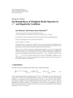
Figure 7 presents the CDF of the expected user through-
put Θ(
·, ·). We can clearly observe from the CDF of the
throughput that the number of users with low throughput
is significantly reduced, compared to a system without
relay stations. Besides, we can observe a major performance
advantage of cooperative relaying in comparison to single-
path relaying. This is of course at the cost of additional sig-
naling and control overhead. Nonetheless, the coordinated
and joint transmission of BSs and RSs seems to be a viable
option especially in those areas where an MS experiences
similar channel conditions to both radio access points.
5.4. Cooperative Relaying in Local Area Test Scenario. In
the local area test scenario, we assess the performance of
cooperative relaying for the deployment given in Figure 4
[27]. We compare two different possibilities. The MSs are
served by the BS or by RS using either single-path relaying
(BS-RS-MS) or cooperative relaying (BS-VAA-MS), where
a Virtual Antenna Array (VAA) is formed by a pair of
cooperating RSs. The RSs forming the VAA are chosen
with the use of a static version of the REACT algorithm as
described in Section 4.3.
The results were obtained for a fixed modulation and
coding scheme based on QPSK modulation and the (4, 5, 7)
convolutional code with the use of the fixed resource
assignment in [27]. Further, an AWGN channel model was
assumed. The presence of an outdoor network is modeled by
setting an average interference power level of
−125 dBm per
subcarrier.
EURASIP Journal on Wireless Communications and Networking 11
10
−1
10
−1
10
−2
10
0
10
0
10
1
Direct transmission
Single-path relaying
Cooperative relaying
Throughput θ (Mbit/s)
Pr(θ(., .) <θ)
Figure 7: User throughput CDF for cooperative relaying in wide
area scenario with 3 RSs per sector.
Distance (m)
0.85
0.9
0.95
1
1.05
1.1
1.15
1.2
1.25
1.3
1.35
10 20 30 40 50 60 70 8090
Distance (m)
5
10
15
20
25
30
35
40
45
Figure 8: User throughput achieved for cooperative relaying in
relation to direct transmission.
TheresultsaredepictedinFigure 8 and show improve-
ments of up to 30% for regions where RS-RS cooperation
can be applied compared to MSs that are served only by the
BS. Analyzing these results one can see that the performance
is largely unaffected in the central part of the scenario and
in the corridors that can be covered by the BS. However,
direct transmission is only advantageous in the central
part and nearby the horizontal walls, halfway between the
vertical ones, where it offers a gain of 10% over cooperative
relaying. As it was already mentioned, the benefits of
deploying relays in the local area scenario can be explained
by numerous walls providing additional shadowing. Hence,
it is advantageous to have additional radio access point.
The BSs serve the MSs in their immediate vicinity. The
other MSs are served cooperatively and experience a higher
throughput.
Table 4: Additional parameters for test scenarios.
Scenario Wide area Metropolitan area Local area
BS tx power per sector 46 dBm 37 dBm 21 dBm
RS tx power 37 dBm 30 dBm 21 dBm
MS tx power 21 dBm 21 dBm 21 dBm
BS antenna 14 dBi 8 dBi 14 dBi
Gain 120
◦
120
◦
Omni
RS antenna 9 dBi 14 dBi/7 dBi 7 dBi
Gain omni 60
◦
/omni omni
MSantenna 0dBi 0dBi 0dBi
Gain Omni Omni Omni
Noise figure 5 dB 5 dB 7 dB
6. Conclusion
In this paper we presented key technologies that allow to
exploit the potential benefits of a relay-based deployment.
In particular we introduced dynamic and flexible resource
assignment in a relay enhanced cell and cooperative relaying.
Our performance results indicate that a relay based
deployment using the proposed resource assignment signifi-
cantly increases the lower percentiles of the user throughput
cumulative distribution function and it improves the cell
throughput compared to a BS only scenario. Our results also
show that the performance gains are lost, if a static resource
partitioning is used.
The cooperative relaying solution utilizes a virtual
antenna array formed by the base station and the relay station
antennas. Cooperative relaying reduces the number of users
with low throughput even further than single-path relaying.
Even though these assessment results have been obtained
for WINNER OFDMA parameters, they give also insights
on the potential benefits of relays for OFDMA-based cellular
systems like WiMAX and 3GPP Long-Term Evolution (LTE).
In particular the presented results on dynamic resource
assignment are applicable to the IEEE802.16j draft standard
[49].
Appendices
A. Additional Simulation Parameters
Ta bl e 4 presents selected simulation parameters and Tab le 5
the OFDMA parameters of the WINNER system in both
FDDandTDDmode.
The numerical evaluations have been carried out for a
carrier frequency of 3.95 GHz which has not been allocated
to IMT systems at the World Radio Communications
Conference 2007. Nevertheless, for example, 200 MHz have
been allocated between 3.4 and 3.6 GHz and changing
the carrier frequency, for example, to 3.55 GHz will not
significantly change the results or our conclusions. The
5 GHz carrier frequency chosen for the local area is close
to the license exempt Universal-Networking Information
Infrastructure (U-NII, 5.15–5.35 GHz) band and the upper
Industry Science and Medical (ISM, 5.725–5.825) band.
12 EURASIP Journal on Wireless Communications and Networking
Table 5: WINNER OFDMA parameters for Downlink [36].
Mode TDD FDD
Bandwidth 100 MHz 50 MHz
Carrier frequency
3.95 GHz 3.95 GHz
5 GHz (local area)
Frame length 0.6912 ms 0.6912 ms
OFDM symbols/frame 30 24
Subcarrier spacing 48.828 KHz 39.063kHz
Cyclic prefix 1.2 μs3.2μs
No. used subcarriers 1840 1152
Signal bandwidth 90 MHz 45MHz
No. subcarriers/chunk 8 8
No. symbols/chunk 120 96
No. chunks in DL/frame 230 2
× 144
Control and pilot
16 16
symbols/chunks
Duplex guard time 0 8.4 μs
B. Pathloss-Equations for
Wide Area Test Scenario
The path-loss equation [35] for the BS to MS link, assuming
an urban macro-cell model (C2) with non-line-of-sight
(NLOS), is given by
PL
BS-MS
[
dB
]
=
44.9 − 6.55 log
10
(
h
BS
)
log
10
(
d
)
+34.46
+5.83 log
10
(
h
BS
)
+23log
10
f
5.0
+ σ,
(B.1)
where h
BS
is the BS antenna height in meters, f the carrier
frequency in GHz, d the transmitter-receiver separation in
meters, and σ
= 8 dB the standard deviation of the shadow
fading. The link BS to RS is expected to be 3 dB better with
respect to the link BS to MS due to some intelligence when
selecting the RS location:
PL
BS-RS
[
dB
]
= PL
BS-MS
− 3
. (B.2)
For the interfering link from other BS, the path loss is
obtained as in (B.1).
Alternatively, a more careful planning of the relay
locations with line-of-sight (LOS) or obstructed LOS can be
assumed. In that case the path-loss equation for the BS-RS
link can be found from a stationary feeder model (B5f):
PL
BS-RS
[
dB
]
= 23.8log
10
(
d
)
+57.5 + 23 log
10
f
5.0
+ σ,
(B.3)
where σ
= 8dB.
The path loss for the RS to MS link is based on an urban
micro-cell model (B1) and can be found in LOS situations as
PL
LOS
[
dB
]
= max
22.7log
10
(
d
1
)
+41.0 + 20 log
10
f
5.0
+ σ,PL
Free
,30m<d
1
<d
BP
,
d
BP
=
4
(
h
RS
− 1.0
)(
h
MS
− 1.0
)
f
c
,
(B.4)
where c denotes the speed of light and σ
= 3dB.Forh
RS
=
5mandh
MS
= 1.5m,whereh
RS
and h
MS
refer to the heights
of RS and MS antennas, the breakpoint is at d
BP
= 53 m;
PL
Free
is the path loss in free space. In NLOS situations the
path loss can be found as
PL
NLOS
[
dB
]
= PL
LOS
(
d
1
)
+20
− 12.5n
j
+10n
j
log
10
(
d
2
)
+ σ,
n
j
= max{
(
2.8
− 0.0024d
1
)
,1.84
}
10 m <d
2
< 2km
(B.5)
with σ
= 4 dB. We assume a geometry for d
1
and d
2
,
where the RS and MS are located in perpendicular streets.
Furthermore, d
1
is the distance from the RS to the midpoint
of the crossing and d
2
is the distance from the midpoint of
the crossing to the MS whereas d
1
= d
2
.
C. Pathloss-Equation for
Metropolitan Area Scenario
A LOS link is assumed for nodes in the same street and a
NLOS link for nodes in different streets and MSs are located
inside of a building or in a street. The corresponding channel
and path-loss models for all links are specified in [35]: urban
micro-cell B1 LOS for nodes in the same street (B.4), urban
micro-cell B1 NLOS for nodes in different streets (B.5), and
the outdoor to indoor urban micro-cell model (B4).
The outdoor to indoor path-loss model consists of three
components, the outdoor path-loss PL
B1
as defined by the
urban micro-cell (B1 LOS/B1 NLOS) model, the penetration
loss into the building PL
w
, and the indoor path-loss PL
i
.The
path-loss equation is given as
PL
o2i
[
dB
]
= min
n
PL
n,B1
+PL
n,w
+PL
n,i
, n = 1, 2, 3,4,
(C.6)
where the path loss is calculated using the four points n
=
1, 2,3, and 4 of the outer walls of the building blocks that are
closest to the indoor MS, and
PL
n,B1
[
dB
]
= PL
B1
d
n,o
,
PL
n,w
[
dB
]
= 13 + 15(1 − cos Θ
n
)
2
PL
n,i
[
dB
]
= 0.5d
n,i
.
,(C.7)
EURASIP Journal on Wireless Communications and Networking 13
Moreover, d
n,o
denotes the distance to the closest point in all
four streets surrounding the building block. Please note that
d
n,o
is the distance traveled in the streets to reach these points
and that the B1 path-loss model distinguishes whether the
two nodes are in the same street or not, that is, line-of-sight
(LOS) or NLOS path-loss model is used. Furthermore, Θ
n
denotes the angle relative to the normal of the wall under
which the signal is entering the building at the points closest
to the MS, and d
n,i
denotes the distance to the MS inside the
building block.
D. Pathloss-Equation for Local Area Scenario
A LOS or NLOS office propagation model (A1) [35]is
employed depending on the presence of walls between the
BS, RSs, and MSs. In particular LOS propagation model is
used between BS and RS as well as between BS/RS and MS
if there is a direct visibility. The LOS model is given by the
following formula:
PL
LOS
[
dB
]
= 18.7log
10
(
d
)
+46.8+σ,
(D.8)
where d denotes the distance in meters between the transmit-
ter and the receiver and σ represents the standard deviation
of the shadow fading and is equal to 3 dB. The NLOS
propagation model is defined as
PL
NLOS
[
dB
]
= 20.0log
10
(
d
)
+46.4+5n
w
+ σ,(D.9)
where n
w
denotes the number of walls on a direct line
between the transmitter and the receiver and σ
= 6dB.For
the simulations light walls of the same type for all walls were
assumed.
Acknowledgments
This work has been performed in the framework of the
EU funded project IST-4-027756 WINNER II, which is
partly funded by the European Union. The authors like
to specifically acknowledge the contributing partners of
the WINNER relaying task Daniel Schultz, Ralf Pabst,
Niklas Johansson, Luca Coletti, and Mark Naden for their
contribution to the development of the dynamic resource
assignment framework and the cooperative relaying concept.
Further, we would like to thank Carl Wijting and Kimmo
Valkealahti for their contribution to the soft frequency reuse
scheme and Elena Costa, Antonio Frediani, Ying Zhang,
and Antonio Capone for their contribution to the dynamic
resource sharing scheme.
References
[1]N.Esseling,B.Walke,andR.Pabst,Fixed Relays for
Next Generation Wireless Systems, vol. 71–91, Springer Sci-
ence+Buisness Media, New York, NY, USA, 5 edition, 2005.
[2] IEEE802.16, “TSGj -Mobile Multihop Relaying (MMR),”
2007.
[3] 3GPP, REV-080060, “Report of 3GPP TSG RAN IMT-
Advanced Workshop,” April 2008.
[4] “IST-Winner,” .
[5] ITU-R WP8F Document 8F/TEMP/1252-E, “Proposed new
test environments and channel models of preliminary draft
new report M.[Imt.Eval],” in Proceedings of the 2nd Meeting
of Working Party 8F, Kyoto, Japan, May 2007.
[6] R. Pabst, D. Schultz, and B. Walke, “Performance evaluation
of a relaybased 4G network deployment with combined
SDMA/OFDMA and resource partitioning,” in Proceedings
of the IEEE Vehicular Technology Conference (VTC ’08),
Singapore, May 2008.
[7] V. Genc, S. Murphy, Y. Yu, and J. Murphy, “IEEE 802.16j relay-
based wireless access networks: an overview,” IEEE Wireless
Communications, vol. 15, no. 5, pp. 56–63, 2008.
[8] I. -K. Fu, W. -H. Sheen, and F. -C. Ren, “Deployment and
radio resource reuse in IEEE 802.16j multi-hop relay network
in Manhattanlike environment,” in 6th International Confer-
ence on Information, Communications and Signal Processing,
Singapore, December 2007.
[9] V. Genc, S. Murphy, and J. Murphy, “Performance analysis of
transparent relays in 802.16j MMR networks,” in Proceedings
of the 6th International Symposium on Modeling and Optimiza-
tion in Mobile, Ad Hoc, and Wireless Networks, (WiOpt ’08),pp.
273–281, Berlin, Germany, April 2008.
[10] W. Park and S. Bahk, “Resource management policies
for fixed relays in cellular networks,” December 2008,
/>[11] S. Lin, W. H. Sheen, I. Fu, and C. C. Huang, “Resource
scheduling with directional antennas for multi-hop relay net-
works in Manhattanlike environment,” IEEE Mobile Wimax
Symposium, Orlando, Fla, USA, March 2007.
[12] S J. Lin, W H. Sheen, I K. Fu, and C C. Huang, Resource
Scheduling with Directional Antennas for Multi-Hop Relay
Networks in a Manhattan-like Environment, chapter 10, John
Wiley & Sons, 2008.
[13] ETSI, “ETSI; recommendation TR 30.03 Selection procedure
for the choice of radio transmission technologies of the
UMTS,” 1997.
[14] M. Kaneko and P. Popovski, “Radio resource allocation algo-
rithm for relay-aided cellular OFDMA system,” in Proceedings
of the IEEE International Conference on Communications,pp.
4831–4836, Glasgow, Scotland, June 2007.
[15] T. Girici, “Joint power, subcarrier and subframe allocation in
Multihop relay networks,” International Journal of Communi-
cation Systems, vol. 22, no. 7, pp. 835–855, 2009.
[16] L. Huang, M. Rong, L. Wang, Y. Xue, and E. Schulz, “Resource
scheduling for OFDMA/TDD based relay enhanced cellular
networks,” in Proceedings of the IEEE Wireless Communications
and Networking Conference (WCNC ’07), pp. 1546–1550,
Hong Kong, March 2007.
[17] R. Pabst, D. C. Schultz, and B. H. Walke, “Combined
uplink resource reservation and power control for relay-
based OFDMA systems,” in Proceedings of the IEEE Vehicular
Technology Conference (VTC ’08), pp. 2248–2252, Singapore,
May 2008.
[18] E. Visotsky, Junjik B., R. Peterson, R. Berry, and M. L. Honig,
“On the uplink capacity of an 802.16j system,” in IEEE Wireless
Communications and Networking Conference (WCNC ’08),pp.
2657–2662, Las Vegas, Nev, USA, 2008.
[19] H. Wu, C. Qiao, S. De, and O. Tonguz, “Integrated cellular and
ad hoc relaying system: iCAR,” IEEE Journal on Selected Areas
in Communications, vol. 19, no. 10, pp. 2105–2115, 2001.
[20] Y D. Lin andY C. Hsu, “Multihop cellular: a new architecture
for wireless communications,” in Proceedings of the IEEE
INFOCOM, vol. 3, pp. 1273–1282, Tel Aviv, Israel, March
2000.
14 EURASIP Journal on Wireless Communications and Networking
[21] H. Viswanathan and S. Mukherjee, “Performance of cellular
networks with relays and centralized scheduling,” IEEE Trans-
actions on Wireless Communications, vol. 4, no. 5, pp. 2318–
2328, 2005.
[22] C.Wijting,K.Doppler,K.Kallioj
¨
arvi, et al., “Key technologies
for IMTAdvanced mobile communication systems,” IEEE
Wireless Communications Magazine.
[23] A. Frediani, S. Redana, E. Costa, A. Capone, and Y. Zhang,
“Dynamic resource allocation in relay enhanced cells based
on WINNER system,” in Proceedings of the16th IST Mobile
and Wireless Communications Summit, Budapest, Ungary, July
2007.
[24] S. Redana, L. Coletti, A. Capone, and L. Moretti, “A novel
resource request and allocation strategy for relay based
beyond 3G networks,” in Proceedings of the 8th World Wireless
Congress, pp. 95–100, San Francisco, Calif, USA, May 2007.
[25] K. Doppler, C. Wijting, and K. Valkealahti, “On the benefits of
relays in a metropolitan area network,” in Proceedings of the
IEEE Vehicular Technology Conference (VTC ’08), pp. 2301–
2305, Singapore, May 2008.
[26] P. Rost, F. Boye, and G. Fettweis, “System performance
analysis of single-path and cooperative MIMO relaying,” in
Proceedings of the IEEE Vehicular Technology Conference (VTC
’08), Calgary, Canada, September 2008.
[27] M. W
´
odczak, “Cooperative relaying in an indoor environ-
ment,” in ICT Mobile Summit, Stockholm, Sweden, June 2008.
[28] K. Doppler, C. Wijting, and K. Valkealahti, “Interference
Aware Scheduling for Soft Frequency Reuse,” in Proceedings
of the IEEE Vehicular Technology Conference (VTC ’09),
Barcelona, Spain, April 2009.
[29] M. Werner, M. Naden, P. Moberg, et al., “Cost assessment and
optimization methods for multi-node radio access networks,”
in Proceedings of the IEEE Vehicular Technology Conference
(VTC ’08), pp. 2601–2605, 2008.
[30] P. Moberg, P. Skillermark, N. Johansson, and A. Furusk
¨
ar,
“Performance and dost evaluation of fixed relay odes in
future wide area cellular networks,” in Proceedings of the IEEE
International Symposium on Per sonal, Indoor and Mobile Radio
Communications, Athens, Greece, September 2007.
[31] B. Timus, “Cost analysis issues in a wireless multihop
architecture with fixed relays,” in Proceedings of the IEEE
Vehicular Technology Conference(VTC ’05), vol. 61, pp. 3178–
3182, Stockholm, Sweden, May 2005.
[32] K. Johansson, A. Furusk
¨
ar, P. Karlsson, and J. Zander, “Rela-
tion between base station characteristics and cost structure
in cellular systems,” in Proceedings of the IEEE International
Symposium on Personal, Indoor and Mobile Radio Communi-
cations, (PIMRC ’04), vol. 4, pp. 2627–2631, Barcelona, Spain,
September 2004.
[33] C. Wijting, K. Doppler, K. Kallioj
¨
arvi, et al., “WINNER
II system concept: advanced radio technologies for future
wireless systems,” in Proceedings of the ICT-Mobile Summit
2008, Stockholm, Sweden, June 2008.
[34] M. Narand
ˇ
zic, C. Schneider, R. Thom
¨
a, T. J
¨
ams
¨
a, P. Ky
¨
osti, and
X. Zhao, “Comparison of SCM, SCME, and WINNER channel
models,” in Proceedings of the IEEE Vehicular Technology
Conference, pp. 413–417, Dublin, Ireland, April 2007.
[35] WINNER II D1.1.2, “WINNER II channel models,” September
2007,
/>[36] WINNER II D6.13.14, “WINNER II System Concept
Description,” November 2007, />deliverables.html.
[37] A. Osseiran, V. Stankovic, E. Jorswieck, T. Wild, M. Fuchs, and
M. Olsson, “A MIMO framework for 4G systems: WINNER
concept and results,” in Proceedings of the IEEE Workshop
on Signal Processing Advances in Wireless Communications,
(SPAWC ’07), Helsinki, Finland, June 2007.
[38] E. Costa, A. Frediani, S. Redana, and Y. Zhang, “Dynamic
resource allocation in relay enhanced cells,” in Proceedings of
the 16th IST Mobile and Wireless Communications Summit,
Paris, France, April 2007.
[39] J. N. Laneman, D. N. C. Tse, and G. W. Wornell, “Cooperative
diversity in wireless networks: efficient protocols and outage
behavior,” IEEE Transactions on Informat ion Theory, vol. 50,
no. 12, pp. 3062–3080, 2004.
[40] P. Herhold, E. Zimmermann, and G. Fettweis, “A simple
cooperative extension to wireless relaying,” in Proceedings of
the International Zurich Seminar on Digital Communications
(IZS ’04), pp. 36–39, Zurich, Switzerland, February 2004.
[41] P. Rost and G. Fettweis, “A cooperative relaying scheme
without the need for modulation with increased spectral
efficiency,” in Proceedings of the IEEE Vehicular Technology
Conference(VTC ’06), pp. 256–260, Montral, Canada, 2006.
[42] E. Zimmermann, P. Herhold, and G. Fettweis, “On the
performance of cooperative diversity protocols in practical
wireless systems,” in Proceedings of the 58th IEEE Vehicular
Technology Conference(VTC ’03), vol. 58, no. 4, pp. 2212–2216,
Orlando, Fla, USA, 2003.
[43] E. Zimmermann, P. Herhold, and G. Fettweis, “On the
performance of cooperative relaying protocols in wireless
networks,” European Transactions on Telecommunications, vol.
16, no. 1, pp. 5–16, 2005.
[44] E. Zimmermann, P. Herhold, and G. Fettweis, “Cooperative
multi-hop transmission in wireless networks,” Computer
Networks, vol. 49, no. 3, pp. 299–324, 2005.
[45] M. Dohler, A. Gkelias, and H. Aghvami, “A resource allocation
strategy for distributed MIMO multi-hop communication
systems,” IEEE Communications Letters, vol. 8, no. 2, pp. 99–
101, 2004.
[46] M. K. Karakayali, G. J. Foschini, R. A. Valenzuelat, and R.
D. Yates, “On the maximum common rate achievable in a
coordinated network,” in IEEE International Conference on
Communications, vol. 9, pp. 4333–4338, 2006.
[47] M. H. M. Costa, “Writing on dirty paper,” IEEE Transactions
on Information Theory, vol. 29, no. 3, pp. 439–441, 1983.
[48] M. W
´
odczak, “Extended REACT—Routing information
enhanced algorithm for cooperative transmission,” in Pro-
ceedings of the 16th IST Mobile and Wireless Communications
Summit, Budapest, Hungary, July 2007.
[49] P802.16j/D1, “Draft standard for local and metropolitan area
networks–Part 16: air interface for fixed and mobile broad-
band wireless access systems–Multihop relay specification,”
August 2007.
[50] K. Br
¨
ueninghaus, D. Astely, T. S
¨
alzer, et al., “Link performance
models for system level simulations of broadband radio access
systems,” in IEEE International Symposium on Personal, Indoor
and Mobile Radio Communications, (PIMRC ’05), vol. 4, pp.
2306–2311, Berlin, Germany, September 2005.
[51] Recommendation ITU-R M1645, “Framework and overall
objectives of the future development of IMT-2000 and systems
beyond IMT-2000,” 2003.