Waste Management 2009 Part 6 pptx
Bạn đang xem bản rút gọn của tài liệu. Xem và tải ngay bản đầy đủ của tài liệu tại đây (2.47 MB, 18 trang )
Composting Barrel for Sustainable Organic Waste Management in Bangladesh
83
in the conventional barrel is higher than the desired moisture content due to lack of aeration
in all stages of the composting operation than that of the modified barrel.
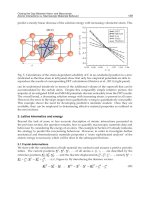
The result of chemical analysis of compost sample is presented in Figure 6.
Nitrogen Phosphorus Potassium
0.0
0.2
0.4
0.6
0.8
1.0
1.2
1.4
%
nutrients
(before modification)
(after modification)
Fig. 6. Quantity of different nutrients present in the compost sample
12345
0
5
10
15
20
25
C/N ratio
Compost sample
(before modification)
(after modification)
Fig. 7. Carbon- Nitrogen ratio of ready compost samples
As the ultimate goal of the composting of organic solid waste is to use the compost as a soil
conditioner and also as a fertilizer in the agricultural field, it is important to examine the
values of different nutrients. All chemical analyses were performed according to the
standard methods of soil and compost analysis (Goyal, 2005; Sundberg, 2004; Jackson, 1973).
It is observed that the values of nutrients i.e. Nitrogen, Phosphorus and Potassium (NPK)
were very much similar as reported in other countries (Asija et al., 1984). The NPK values
Waste Management
84
were lower than the ideal values (N=1.5%, P=1.2%, K=0.8%) when the conventional barrel
was used because of the lack of aeration during the composting (Verma et al., 1999).
Decomposition of organic matter is brought about by microorganisms that use the carbon as
a source of energy and nitrogen for building cell structure. More carbon than nitrogen is
needed. If the excess of carbon is too great, decomposition decreases when the nitrogen is
used up and some of the organisms die (Nakasaki et al., 2005, Polprasert, 1996). The stored
nitrogen is then used by other organisms to form new cell material. Figure 7 shows that the
carbon-nitrogen (C/N) ratio of the ready compost varies from 11 to 14 in different samples
in the study area after the modification. In the case of conventional barrel reactor the C/N
ratio was found to be higher (above 24) than the recommended values (12-16). The compost
from the conventional barrel would not be suitable for agricultural land application since
the excess carbon would tend to utilize nitrogen in the soil to build cell protoplasm,
consequently resulting in loss of nitrogen in the soil on which it would be applied.
4. Financial assessment of modified barrel composting project
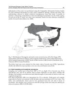
The generation of solid waste was found to increase almost linearly with increasing of per
capita income. Figure 8 shows the variation of the waste generation rate with the variation
of per capita (person) income of selected low and middle-income family in the study area.
When the per capita income per month is US$6-8, per capita waste generation is about 0.27
kg/day and when per capita income per month is US$67-75, per capita waste generation is
about 0.38 kg/day.
Three different revenues were assessed from the modified composting barrel plant. These are
• fees charged by the collection scheme to the service beneficiaries (households) on a
monthly basis (approximately US$0.3).
• revenues from the sale of compost (US$0.08 /kg) and revenues from the sale of
recyclable materials like hard plastics, card board, glass and metals.
6-8
8-10
10-11
11-15
15-17
17-20
30-34
50-58
67-75
0.00 0.05 0.10 0.15 0.20 0.25 0.30 0.35 0.40
waste generation rate (kg/capita/day)
income range (USD/capita/month)
Fig. 8. Variation of per capita waste generation rate with respect to per capita income
Composting Barrel for Sustainable Organic Waste Management in Bangladesh
85
Item
Cost
US$/year
Item
Revenue
US$/year
Depreciation cost for collection
Investment (life time 5 years)
2422 Collection fees 3000
Compost sales 12458
Operation cost for collection
and composting
10152 Recyclables 333
Total 12574 Total 15788
Table 2. Yearly costs and revenues of modified composting barrel plant (including
collection)
Table 2 gives the summary of costs and revenues for a modified composting plant of
capacity of 1.865 tons/day on a yearly basis. It is seen that the plant is financially viable
when operating at 1.865 tons/day. It is evident that the revenues from the collection fees are
partly cross-subsidizing the composting activities. Hence, it seems advisable to combine
composting activities with neighborhood waste collection to ensure a viable operation of the
scheme. An additional advantage of a combination of waste collection and composting is the
direct influence on improving waste composition for composting in the collection area, as
continuous contact with the customers is available and appropriate information may be
disseminated (e.g. promoting source separation and separate collection). The depreciation
was calculated using a lifetime of 5 years and interest rate of 15%. The cost items comprise
barrel modification plant set up, salaries and uniforms of the employees both for collection
and in the composting plant, maintenance of collection vehicles, and expenses for electricity
and water. Total revenues from the sale of the recyclables such as hard plastics, cardboards,
glass and metal are US$333. The benefit-cost ratio of the modified composting barrel plant is
> 1. Financial analysis confirms the results of other investigations on decentralized urban
composting plants, showing that small-scale plants struggle with their economic viability if
all costs have to be covered by the plant revenues (Lardinois & Furedy, 1999). However, our
results show that a plant of capacity 1.865 ton/day may be viable in the study area where
the rent for land is relatively smaller than the capital city as land acquisition in urban areas
is always one financial key obstacle for initiating a composting plant. The decentralized
waste collection and composting activity relieves a certain burden from municipal budgets
in the study area (Zurbrugg et al., 2005). The municipal waste transportation and landfill
costs can be reduced approximately by US$9500 per year. This estimate takes into account
that the composting plant reduces the amount of waste, which needs to be transported by
municipal trucks as well the reduction of the municipal expenses for its final disposal. With
or without municipal support, any composting plant should however focus on long-term
financial feasibility where operational costs are covered by revenues. Therefore, marketing
strategies and the development of a market for compost are crucial for the long term success
of a composting plant (Zurbrugg et al., 2005).
5. Conclusions
Reduction of waste volume was faster in the modified composting barrel than the
conventional barrel reactor. The volume becomes 50% and 70% of its original volume before
Waste Management
86
and after modification of the composting barrel, respectively after 4 weeks. The barrel
composting was operated in the mesophilic and thermophilic temperature bend, which was
very effective for proper composting operation. The quality of compost in terms of C/N
ratio is better in the modified composting barrel than the conventional barrel. Nutrient
concentrations of compost, produced in the modified composting barrel, were also
satisfactory. The biochemical quality of the compost produced in the modified composting
barrel was found suitable. The benefit-cost ratio for large scale modified composting barrel
plants is more than 1. Thus, the modified composting barrel can be an eco-friendly, efficient
and a sustainable solution of organic waste management alternative in Bangladesh.
6. References
Ahmed, M. F., Rahman, M. M., 2000. Water Supply and Sanitation: Rural and low income
urban communities, ITN-Bangladesh, Center for Water Supply and Waste
Management, BUET, Dhaka, Bangladesh.
ASija, A. K., Pareek, R. P., Singhania, R. A., Singh, S., 1984. Effect of method of preparation
and enrichment on the quality of manure. Journal of Indian Society of Soil Sci. 32,
323-329.
Bhide, A. D., Sundersan B. B., 1983. Solid waste management in developing countries,
Indian National Scientific Documentation Center, New Delhi.
Chang, I. J.; Tsai, J. J.; Wu, H. K., 2006. Thermophilic composting of food waste. Bioresource
Technol. 97, 116-122.
Dresboll, B. D., Kristensen, K. T., 2005. Delayed nutrient application affects mineralization
rate during composting of plant residues. Bioresource Technol. 96,
1093-1101.
Fang, M., Wong, J. W. C., 1999. Effect of lime amendment on availability of heavy metals
and maturation in sewage sludge composting. Journal of Environmental Pollution.
106(1), 83-89.
Golueke, C. G., 1972. Biological Reclamation of Solid Wastes. Rodale Press, Emmanus,
USA.
Gantzer C., P. Gaspard, L. Galvez, A. Huyard, N. Dumouthier, J. Schwartzbrod. 2001.
Monitoring of bacterial and parasitological contamination during various treatment
of sludge. Wat. Res. 35(16), 3763-3770.
Goyal, S., Dhull, S. K. and Kapoor, K. K., 2005. Chemical and biological changes during
composting of different organic waste and assessment of compost maturity.
Bioresource Technology, 96, 1584-1591.
Hong, J. H., Park, K. J., 2005. Compost biofiltration of ammonia gas from bin composting.
Bioresource Technology, 96, 741-745.
Iyengar, R. S., Bhave, P.P., 2006. In-Vessel composting of household wastes. Waste
Management. 26, 1070–1080.
Jackson, M. L., 1973. Chemical analysis of soil. McGraw Hill Publications Company.
Li, G. X., Zhang, F. S., 2000. Solid waste composting and production of fertilizer. Chinese
Chemical Industry Press, Beijing, P R China.
Composting Barrel for Sustainable Organic Waste Management in Bangladesh
87
Moqsud, M. A., 2003. A study on composting of solid waste. A Thesis of Masters of Science
in Environmental Engineering, Bangladesh University of Engineering and
Technology, Dhaka, Bangladesh.
Moqsud, M. A; Rahman, M. H., 2004. Composting of Kitchen garbage in Bangladesh.
Proceedings of the sixth international summer symposium, Japan Society of Civil
Engineering, Saitama, Japan, p. 413-416.
Moqsud, M.A; Rahman, M.H., 2005. Biochemical quality of compost from kitchen garbage of
Bangladesh. Proceedings of the 20
th
International conference on Solid Waste
Technology and Management, Philadelphia, p. 440-447, USA.
Moqsud, M.A, Rahman, M.H, Hayashi, S., Du, Y.J., 2005a. An assessment of modified
composting barrel for sustainable waste management in tropical regions. 4
th
International conference on Environmental Informatics, July 26-28, Xiamen, China.
p. 130-136.
Nakasaki, K.; Yaguchi, H., Sasaki, Y., Kubota, H., 1993. Effects of pH control on composting
of garbage. Waste management and Research. 11(2), 117-125.
Pfammatter R., Schertenleib R., 1996. Non-governmental refuse collection in low-income
urban areas. Lessons learned from selected in Asia, Africa and Latin America.
SANDEC Report No.1/96.Water and sanitation in developing countries
EAWAG/SANDEC, Duebendrof , Switzerland.
Polprasert, C., 1996. Organic waste recycling-technology and management. Wiley,
Chichester, west Sussex, England.
Rahman, M. H., 1993. Recycling of solid waste in Bangladesh. The International Journal of
Environmental Education & Information.UK, 12(4), 337-342.
Rahman, M. H., 2004. Composting of Solid waste in Bangladesh. Proceedings of the 19
th
international conference on Solid Waste Technology and Management,
Philadelphia, USA p 45-49.
Sinha, A. H. M. M. and Enayetullah, I., 2001. Solid waste management with Resource
recovery options. Proceeding of the International Conference on Professional
Development Program 4, Center for Environmental and resource Management,
Dhaka, 2-4 February, p. 32-37.
Sujauddin, M., Huda S. M. S, Hoque, R., 2008. Household solid waste characteristics
and management in Chittagong, Bangladesh. Waste Management 28,
1688-1695.
Sundberg, C., Smars, S., 2004. Low pH as an inhibiting factor in the transition from
mesophilic to thermophilic phase in composting. Bioresource Technol. 96, 746-752.
Tchobanoglous, G., 1977. Solid Waste: Engineering Principles and Management Issue,
McGraw Hill Publications Company, New York.
Verma, L. N., Rawat, A. K., Rathore, G. S., 1999. Composting process as influenced by the
method of aeration. Journal of Indian Society of soil sci. 47 (2), 368-371.
Vesilind, P. A., Rimer, A. E., 1981. Unit operations in resource recovery engineering,
Prentice-Hall, Inc, New Jercy.
Witter, E., Lopeaz-Real, J. M., 1988. Nitrogen losses during the composting of sewage sludge
and the effectiveness of clay soil, zeolite and compost in adsorbing the volatilized
ammonia. Biological Wastes 23, 279-294.
Waste Management
88
Zheng, G. D., Chen, T. B., 2004. Dynamic of Lead specialization in sewage sludge
composting. Journal of Water Sci. and Technol. 50(9), 75-82.
Zurbrugg, C., Drescher, S., Rytz, I., Sinha, A. M., Enayettullah, I., 2005. Decentralized
composting in Bangladesh, a win-win situation for all stakeholders. Resources
conservation and recycling. 43 , 281-292
6
Solid Waste Management
through the Application of Thermal Methods
Konstantinos Moustakas and Maria Loizidou
National Technical University of Athens,
School of Chemical Engineering,
Unit of Environmental Science & Technology
9, Heroon Polytechniou Street, Zographou Campus, Athens
Greece
1. Introduction
Human life in modern societies is inevitably related to waste generation. Around 255
million tones of municipal solid waste were generated in the 27 Member-States of the
European Union in 2006, an increase of 13% in comparison to 1995. This represented an
average of 517 kg of municipal waste per capita, an increase of 9% over 1995. Therefore, it is
not strange that waste management has become a crucial subject with increasing interest for
scientists, local authorities, companies and simple citizens.
The effective management of solid waste involves the application of various treatment
methods, technologies and practices. All applied technologies and systems must ensure the
protection of the public health and the environment. Apart from sanitary landfill,
mechanical recycling and common recycling routes for different target materials, the
technologies that are applied for the management of domestic solid waste include biological
treatment (composting, anaerobic digestion) and thermal treatment technologies
(incineration, pyrolysis, gasification, plasma technology).
Fig. 1. Different biological and thermal methods for solid waste management
Waste Management
90
This chapter focuses on the description of the alternative thermal practices for municipal
solid waste management. Thermal methods for waste management aim at the reduction of
the waste volume, the conversion of waste into harmless materials and the utilization of the
energy that is hidden within waste as heat, steam, electrical energy or combustible material.
They include all processes converting the waste content into gas, liquid and solid products
with simultaneous or consequent release of thermal energy.
According to the New Waste Framework Directive 2008/98/EC, the waste treatment
methods are categorized as “Disposal” or “Recovery” and the thermal management
practices that are accompanied by significant energy recovery are included in the
“Recovery” category. In addition, the pyramid of the priorities in the waste management
sector shows that energy recovery is more desired option in relation to the final disposal.
Fig. 2. Pyramid of the priorities in the waste management sector
That is why more and more countries around the world develop and apply Waste-to-Energy
technologies in order to handle the constantly increasing generated municipal waste.
Technologically advanced countries in the domain of waste management are characterized
by increased recycling rates and, at the same time, operation of a high number of Waste-to-
Energy facilities (around 420 in the 27 European Member-States). More specifically, on the
basis of Eurostat data the percentages of municipal waste treated with thermal methods for
the year 2007 in Denmark, Sweden, Luxembourg, Netherlands, France (Autret et al., 2007),
Germany, Belgium and Austria were 53%, 47%, 47%, 38%, 36%, 35%, 34% and 28%
respectively. On the other hand, there are still Member-States that do not apply thermal
techniques in order to handle the generated municipal waste, especially in the southern
Europe and the Baltic Sea. Such countries include Bulgaria, Estonia, Iceland, Cyprus, Latvia,
Lithuania, Slovenia, Malta, Poland, Romania and Greece.
General information about the use of thermal technologies for solid waste management
around Europe and worldwide is provided. Data referring to incineration – mass burn
combustion, pyrolysis, gasification and plasma technology is presented. The different
aspects of each technology, the indicative respective reactions, as well as the products of
each thermal process, are described. The issue of air emissions and solid residues is
addressed, while the requirements for cleaning systems are also discussed for each case.
Dis
p
osal
Munici
p
al Solid Waste
Prevention
Reuse
Rec
y
clin
g
Recovery
Energy Recovery
Solid Waste Management through the Application of Thermal Methods
91
Finally, the first attempt to treat municipal waste in Greece with the use of gasification /
vitrification process is presented.
2. Incineration
2.1 General
The incineration (combustion) of carbon-based materials in an oxygen-rich environment
(greater than stoichiometric), typically at temperatures higher than 850
o
, produces a waste
gas composed primarily of carbon dioxide (CO
2
) and water (H
2
O). Other air emissions are
nitrogen oxides, sulphur dioxide, etc. The inorganic content of the waste is converted to ash.
This is the most common and well-proven thermal process using a wide variety of fuels.
During the full combustion there is oxygen in excess and, consequently, the stoichiometric
coefficient of oxygen in the combustion reaction is higher than the value “1”. In theory, if the
coefficient is equal to “1”, no carbon monoxide (CO) is produced and the average gas
temperature is 1,200°C. The reactions that are then taking place are:
C + O
2
→ CO
2
+ 393.77J (1)
CxHy + (x+ y/4) O
2
→ xCO
2
+ y/2 H
2
O (2)
In the case of lack of oxygen, the reactions are characterized as incomplete combustion ones,
where the produced CO
2
reacts with C that has not been consumed yet and is converted to
CO at higher temperatures.
C + CO
2
+172.58J → 2CO (3)
The object of this thermal treatment method is the reduction of the volume of the treated waste
with simultaneous utilization of the contained energy. The recovered energy could be used for:
• heating
• steam production
• electric energy production
The typical amount of net energy that can be produced per ton of domestic waste is about
0.7 MWh of electricity and 2 MWh of district heating. Thus, incinerating about 600 tones of
waste per day, about 17 MW of electrical power and 1,200 MWh district heating could be
produced each day.
The method could be applied for the treatment of mixed solid waste as well as for the
treatment of pre-selected waste. It can reduce the volume of the municipal solid waste by
90% and its weight by 75%. The incineration technology is viable for the thermal treatment
of high quantities of solid waste (more than 100,000 tones per year).
A number of preconditions have to be satisfied so that the complete combustion of the
treated solid waste takes place:
• adequate fuel material and oxidation means at the combustion heart
• achievable ignition temperature
• suitable mixture proportion
• continuous removal of the gases that are produced during combustion
• continuous removal of the combustion residues
• maintenance of suitable temperature within the furnace
• turbulent flow of gases
• adequate residence time of waste at the combustion area (Gidarakos, 2006).
Waste Management
92
Fig. 3. A schematic diagram of incineration process
The existing European legislative framework via the Directive 2000/76/EC prevents and
limits as far as practicable negative effects on the environment, in particular pollution by
emissions into air, soil, surface water and groundwater, and the resulting risks to human
health, from the incineration and co-incineration of waste (European Commission, 2000).
Photo 1. MSW incineration plants in Amsterdam, Brescia & Vienna respectively
Solid Waste Management through the Application of Thermal Methods
93
2.2 Typical Incineration plant
A typical incineration plant includes:
Weighing System
The system for weighing solid waste aims at the control and recording of the incoming
loads and it has to be practical so as to minimize the time that vehicles remain at this
point.
Reception Site
Due to the fact that waste does not arrive on continuous basis (contrary to the feeding of the
facility), the existence of waste reception and temporary storage site is considered necessary.
The design of the site is made in a way that the following are ensured:
• the unloading time is as little as possible
• all transferred waste is received
• the homogeneity of the waste that will be used as feeding material is achieved
• the smooth feeding of the facility is ensured
Moreover, the design of the reception site should be based on the minimization of the
environmental consequences. For instance, the solid waste should remain for maximum two
days so as to avoid odours, while the bottom of the site has to be characterised by
weathering to allow the leachates and washing wastewater to go away.
Feeding System
The feeding system has to be adapted to the rate and feeding velocity of the installation.
Combustion Hearths
The ignition of solid waste at incineration facilities is achieved through the use of specific
burner, which operates with secondary fuel. Basic parameters for the appropriate operation
of the combustion hearths are:
• achievement of the minimum desired temperature
• adequate combustion time
• achievement of turbulence conditions / homogenous waste incineration
Boiler
The boiler is the system with which the energy content of the fuel material (hot off-gases)
can be utilized in a suitable way through steam production (e.g. at neighbouring industrial
facilities or for the heating of urban areas. Pressure, temperature and steam production rate
are basic parameters for the effective operation of the boiler.
System for the removal of residues
Residues represent 20 - 40% of the weight of the initial waste and are categorized into:
• Residues that go out of the grates: 20 - 35%
• Residues that go through the grates: 1 - 2%
The residues are collected at hoppers where they are transferred with specific system for
cooling.
Emission control system
The role of the emission system control focuses on particles, HCl, HF, SO
2
, dioxins and
heavy metals and is discussed below (Niessen, 2002).
Waste Management
94
2.3 Typical emissions from incinerations
The emissions derived from the operation of typical incinerations plants include:
1. Air emissions
The generated air emissions contain the typical combustion products (CO, CO
2
, NO
x
, SO
2
),
excess of oxygen, dust particles as well as other compounds. The presence and the
concentration of other compounds, such as ΗCl, HF, suspended particles which contain
heavy metals, dioxins and furans, depend on the composition of the waste that is subjected
to incineration. During incineration, a quantity of 4,000 – 5,000 m
3
of air emissions is
generated per ton of waste.
Air emissions must be controlled by applying appropriate anti-pollution systems, such as:
• Bagfilters
• Electrostatic filters
• Cyclones
• Wet cleaning systems, e.g. scrubbers, wet cleaning towers, rotate sprayers, etc.
Dioxin or furan refers to molecules or compounds composed of carbon and oxygen. These
compounds when reacting with halogens, such as chlorine or bromine, acquire toxic
properties. Most research on halogenated dioxin and furan has been concerned with
chlorinated species. It is generally accepted that dioxin and furan are by-products of
combustion processes including domestic and medical waste combustion or incineration
processes. In combustion processes, hydrocarbon precursors react with chlorinated
compounds or molecules to form furans or/and dioxins. They may also be generated in a
post-combustion flue gas cooling system due to the presence of precursor compounds, free
chlorine, or unburned carbon and copper species in the fly ash particles.
The toxic influence of dioxins and furans had not been made clear until the end of the
decade of 80. The application of the MACT Regulations led to the drastic reduction of the
TEQ-Toxic equivalent of the dioxin emissions. As a result, the dioxin emissions have been
limited to one thousandth in relation to the year 1987, reaching values lower than 10 gr TEQ
per year (Fig. 4). It should also be noted that on the basis of data provided by the US EPA
the uncontrolled burning of waste is considered as the main source of dioxins, producing
around 600 gr annually.
Dioxins and furans are produced in almost all combustion processes, in the gas phase, while
the exact mechanism for their formation is not known. It is known that their formation
temperature is 300C°, temperatures where two reactions are possible, formation and
decomposition. The existence of chlorinated organic substances in waste and the increase of
their content in oxygen encourage their formation. Consequently, the operating conditions
of incinerators influence the dioxin formation at higher degree than the waste composition
and PVC quantity included in it.
There are indications for the contribution of dioxins and furans to human cancers, fact that
makes necessary to take basic and secondary measures so as to limit such emissions.
In order to remove the suspended particles and the gas pollutants, different cleaning
systems can be applied. Indicatively, deposition chambers, where 40% of suspended solids
is removed, cyclones (removal efficiency 60-80%), wet cleaning towers (removal efficiency
80-95%), electrostatic precipitators (removal efficiency 99-99.5%) and bagfilters (removal
efficiency 99.9%) are referred. Apart from the removal of suspended solids, it is often
necessary to remove other gas pollutants in the case that they exceed the limit values (like
HCl generated during the combustion of PVC and oxides of nitrogen, sulphur and
phosphorus. Next, the main cleaning systems that are used for the treatment of the gas
products during incineration are briefly described.
Solid Waste Management through the Application of Thermal Methods
95
Fig. 4. Dioxins emission in the USA (Deriziotis, 2004).
Fig. 5. Cyclones (left), electrostatic precipitators (middle) & bagfilters (right)
Bagfilters: The gases go through porous materials, where the suspended particles are
detained. Depending on the requirements, the material of the filters is from natural fibres,
plastic ones, glass, minerals, etc. Dust that is collected at the filter cells is removed by
vibration or knocks or contrary air provision.
Electrostatic Precipitators (Electro filters): They are consisted of the cathode that can be a
simple thin wire and the anode. Another configuration includes a system of parallel tablets,
with potential difference between them. Voltage with values between 30-80 KV is developed
between the anode and the cathode. When the particles enter the cathode field, they are
charged and the negative ones are moving to the positive pole (anode). The velocity of the
particles depends on the weight and the Coulomb forces that are developed.
Waste Management
96
Cyclones: They are based on the development of centrifugal force at the entry of gases at a
symmetrical area. The particles due to the centrifugal force and the rotary flow are led
towards the walls and then moved downward. Cyclones are often applied together with
electrostatic precipitators (Allsopp et al., 2001).
2. Wastewater
Wastewater is generated by the use of water during the incineration process and in
particular:
• extinguishing of ash (0.1 m
3
of water/tn of waste)
• cooling of air gasses (2 m
3
of water/tn of waste)
• wet absorbance towers (2 m
3
of water/tn of waste)
• electrostatic filters (precipitators)
The wastewater stream contains suspended solids as well as dissolved organic and
inorganic substances. It is characterized as hazardous wastewater and specific treatment is
required prior to its final disposal.
3. Solid residues
The secondary solid residues that are generated during incineration can be categorized as
follows:
• Fly ash: It is the lightest fraction of the generated solid residues and is collected by the
appropriate filters (bagfilters or electrostatic filters). The fly ash contains high
concentrations of heavy metals and is characterized as hazardous waste stream.
• Bottom ash: It is the residue of the incineration process (inorganic matter) and is
collected at the bottom of the incinerator
• Boiler ash
• Filter dust
• Other solid residues generated during the air emissions cleaning
The solid residues stream must be treated prior to their final disposal, while a main portion
of their quantities could be recycled by applying specific processes.
2.4 Types of incinerators
There are various types of incinerators, such as moving grate, fixed grate, rotary-kiln,
fluidized bed, etc (Fig. 6).
Moving grate
The typical incineration plant for domestic solid waste is a moving grate incinerator. The
moving grate enables the movement of waste through the combustion chamber to be
optimized to allow more efficient and complete combustion. A single moving grate boiler
can handle up to 35 tones of waste per hour, and can operate 8,000 hours per year with only
one scheduled stop for inspection and maintenance of about one month's duration. Moving
grate incinerators are sometimes referred to as Municipal Solid Waste Incinerators.
The waste is introduced by a waste crane through the "throat" at one end of the grate, from
where it moves down over the descending grate to the ash pit in the other end. Here the ash
is removed through a water lock.
Part of the combustion air (primary combustion air) is supplied through the grate from
below. This air flow also has the purpose of cooling the grate itself. Cooling is important for
the mechanical strength of the grate, and many moving grates are also water cooled
internally.
Solid Waste Management through the Application of Thermal Methods
97
Secondary combustion air is supplied into the boiler at high speed through nozzles over the
grate. It facilitates complete combustion of the flue gases by introducing turbulence for
better mixing and by ensuring a surplus of oxygen. In multiple/stepped hearth incinerators,
the secondary combustion air is introduced in a separate chamber downstream the primary
combustion chamber.
According to the European Waste Incineration Directive, incineration plants must be
designed to ensure that the flue gases reach a temperature of at least 850 °C for 2 seconds in
order to ensure proper breakdown of organic toxins. In order to comply with this at all
times, it is required to install backup auxiliary burners (often fueled by oil), which are fired
into the boiler in case the heating value of the waste becomes too low to reach this
temperature alone.
The flue gases are then cooled in the superheaters, where the heat is transferred to steam,
heating the steam to typically 400 °C at a pressure of 40 bar for the electricity generation in
the turbine. At this point, the flue gas has a temperature of around 200 °C, and is passed to
the flue gas cleaning system.
Often incineration plants consist of several separate 'boiler lines' (boilers and flue gas
treatment plants), so that waste receival can continue at one boiler line, while the others are
subject to revision.
Fixed grate
The older and simpler type of incinerator was a brick-lined cell with a fixed metal grate over
a lower ash pit, with one opening in the top or side for loading and another opening in the
side for removing incombustible solids called clinkers.
Rotary-kiln
The rotary kiln incinerator is applied by municipalities and by large industrial plants. This
type of incinerator has two chambers, a primary chamber and secondary chamber. The
primary chamber consists of an inclined refractory lined cylindrical tube. Movement of the
cylinder on its axis facilitates movement of waste. In the primary chamber, there is
conversion of solid fraction to gases, through volatilization, destructive distillation and
partial combustion reactions. The secondary chamber is necessary to complete gas phase
combustion reactions.
The clinkers spill out at the end of the cylinder. A tall flue gas stack, fan, or steam jet
supplies the needed draft. Ash drops through the grate, but many particles are carried along
with the hot gases. The particles and any combustible gases may be combusted in an
"afterburner".
Fluidized bed
According to the technology that is applied for this type of incinerator, a strong airflow is
forced through a sand bed. The air seeps through the sand until a point is reached where the
sand particles separate to let the air through and mixing and churning occurs, thus a fluidized
bed is created and fuel and waste can now be introduced (European Commission, 2006).
3. Gasification
3.1 General
Gasification is the thermal process that converts carbon-containing materials, such as coal,
petcoke, biomass, sludge, domestic solid waste to syngas which can then be used to produce
electric power, valuable products, such as chemicals, fertilizers, substitute natural gas,
Waste Management
98
Fig. 6. three types of incinerators: (a) fixed grate, (b) rotary kiln, (c) fluidized bed
hydrogen, steam and transportation fuels. Gasification is defined as a thermal reaction with
insufficient oxygen present for reaction of all hydrocarbons (compounds of carbon,
hydrogen and oxygen molecules) to CO
2
and H
2
O. This is a partial oxidation process which
produces a composite gas (syngas) comprised primarily of hydrogen (H
2
) and carbon
monoxide (CO).
The major benefit of gasification of biowaste is that the product gas can be used directly,
after significant cleaning, to fuel a gas turbine generator which itself will form part of a
Combined Heat and Power (CHP) or Combined-Cycle Gas Turbine system, thus
theoretically improving the overall thermal efficiency of the plant. The main disadvantage is
that there can be more items of large equipment and the capital investment is
correspondingly higher (Yassin et al., 2009).
The main reactions taking place during gasification are:
Oxidation (exothermic) C + O
2
→ CO
2
(4)
Water evaporation reaction (endothermic) C + H
2
O → CO + H
2
(5)
CO + H
2
O → CO
2
+ H
2
(exothermic) (6)
Boudouard Reaction (endothermic) C + CO
2
→ 2CO (7)
CH
4
formation reaction (exothermic) C + 2H
2
→ CH
4
(8)
3.2 Typical gasification plant
A typical gasification plant includes:
A) Feedstock
Gasification enables the capture — in an environmentally beneficial manner — of the
remaining “value” present in a variety of low-grade hydrocarbon materials (“feedstocks”)
that would otherwise have minimal or even negative economic value. Gasifiers can be
designed to run on a single material or a blend of feedstocks:
Solid Waste Management through the Application of Thermal Methods
99
Fig. 7. A schematic diagram of gasification process
• Solids: All types of coal and petroleum coke (a low value byproduct of refining) and
biomass, such as wood waste, agricultural waste and household waste
• Liquids: Liquid refinery residuals (including asphalts, bitumen, and other oil sands
residues) and liquid waste from chemical plants and refineries
• Gas: Natural gas or refinery/chemical off-gas.
B) Gasifier
The core of the gasification system is the gasifier, a pressurized vessel where the feed
material reacts with oxygen (or air) and steam at high temperatures. There are several basic
gasifier designs, distinguished by the use of wet or dry feed, the use of air or oxygen, the
reactor’s flow direction (up-flow, downflow, or circulating), and the gas cooling process.
Currently, gasifiers are capable of handling up to 3,000 tons/day of feedstock throughput
and this will increase in the near future. After being ground into very small particles — or
fed directly (in the case of gas or liquid) — the feedstock is injected into the gasifier, along
with a controlled amount of air or oxygen and steam. Temperatures in a gasifier range from
1,400-2,800 degrees Fahrenheit. The heat and pressure inside the gasifier break apart the
chemical bonds of the feedstock, forming syngas. The syngas consists primarily of H
2
and
CO and, depending upon the specific gasification technology, smaller quantities of CH
4
,
CO
2
, H
2
S, and water vapour. Syngas can be combusted to produce electric power and steam
Waste Management
100
or used as a building block for a variety of chemicals and fuels. Syngas generally has a
heating value of 250-300 Btu/scf, compared to natural gas at approximately 1,000 BTU/scf.
Typically, 70–85% of the carbon in the feedstock is converted into the syngas. The ratio of
carbon monoxide to hydrogen depends in part upon the hydrogen and carbon content of the
feedstock and the type of gasifier used.
C) Oxygen plant
Most gasification systems use almost pure oxygen (as opposed to air) to help facilitate the
reaction in the gasifier. This oxygen (95–99% purity) is generated in a plant using proven
cryogenic technology. The oxygen is then fed into the gasifier through separate co-feed ports
in the feed injector.
D) Gas Clean-Up
The raw syngas produced in the gasifier contains trace levels of impurities that must be
removed prior to its ultimate use. After the gas is cooled, the trace minerals, particulates,
sulphur, mercury, and unconverted carbon are removed at high degree using commercially
proven cleaning processes common to the chemical and refining industries.
For feeds (such as coal) containing mercury, more than 95% of the mercury can be removed
from the syngas using relatively small and commercially available activated carbon beds.
E) By-products
Most solid and liquid feed gasifiers produce a glass-like by-product called slag, which is
non-hazardous and can be used in roadbed construction or as roofing material. Also, in
most gasification plants, more than 99% of the sulphur is removed and recovered either as
elemental sulphur or sulphuric acid.
Hydrogen and carbon monoxide, the major components of syngas, are the basic building
blocks of a number of other products, such as chemicals and fertilizers. In addition, a
gasification plant can be designed to produce more than one product at a time (co-
production or “polygeneration”), such as the production of electricity, steam, and chemicals
(e.g. methanol or ammonia). This polygeneration flexibility allows a facility to increase its
efficiency and improve the economics of its operations.
3.3 Types of gasifiers
The basic types of the gasifiers are:
• Vertical steady bed
• Horizontal steady bed
• Fluidized bed (Groί et al., 2008)
• Multiple hearths
• Rotary kiln
Among the total five types of installations, the development of vertical and horizontal
steady bed facilities, as well as fluidized bed ones is more common.
The facilities of vertical steady bed have advantages, such as the fact that they are simple
and have low capital cost, but they are influenced directly by the variations in the
composition of the incoming waste (it has to be homogenous, e.g. RDF in condensed form -
pellets).
On the basis of the results of pilot applications for units that were operating at temperatures
from 650 to 820
o
C, it was proved that: