Báo cáo hóa học: "Photovoltaic Properties of p-Doped GaAs Nanowire Arrays Grown on n-Type GaAs(111)B Substrate" docx
Bạn đang xem bản rút gọn của tài liệu. Xem và tải ngay bản đầy đủ của tài liệu tại đây (274.78 KB, 4 trang )
NANO EXPRESS
Photovoltaic Properties of p-Doped GaAs Nanowire Arrays
Grown on n-Type GaAs(111)B Substrate
G. E. Cirlin
•
A. D. Bouravleuv
•
I. P. Soshnikov
•
Yu. B. Samsonenko
•
V. G. Dubrovskii
•
E. M. Arakcheeva
•
E. M. Tanklevskaya
•
P. Werner
Received: 5 October 2009 / Accepted: 30 October 2009 / Published online: 14 November 2009
Ó to the authors 2009
Abstract We report on the molecular beam epitaxy
growth of Au-assisted GaAs p-type-doped NW arrays on
the n-type GaAs(111)B substrate and their photovoltaic
properties. The samples are grown at different substrate
temperature within the range from 520 to 580 °C. It is
shown that the dependence of conversion efficiency on the
substrate temperature has a maximum at the substrate
temperature of 550 °C. For the best sample, the conversion
efficiency of 1.65% and the fill factor of 25% are obtained.
Keywords Molecular beam epitaxy Á Nanowires Á
GaAs Á Solar cells Á Photovoltaic properties
Introduction
Aligned NW arrays are very promising building blocks for
various nanoelectronic devices, such as nanolasers [1, 2],
field-effect transistors [3], light-emitting diodes [4, 5] and
field emitters [6, 7]. Compared to polycrystalline films,
vertically oriented NW arrays are particularly advanta-
geous for photovoltaic (PV) application, because the
oriented geometry provides direct conduction paths for
photo-generated carriers to transport from the junction to
the external electrode, thereby resulting in a high carrier
collection efficiency [8, 9]. Moreover, NW arrays have
significantly smaller optical reflectance and enhanced light
absorption in comparison to thin films [10, 11]. Due to the
strain accommodation at the nanowire sidewalls, NWs are
less restricted by lattice mismatch, which provides greater
freedom in the bandgap engineering and the substrate
selection [12]. In most cases, NWs arrays can be formed
via the vapor–liquid–solid growth mechanism [13] using
different epitaxial techniques, such as metal organic
chemical vapor deposition or molecular beam epitaxy
(MBE). One of the most important features of MBE growth
is the ability to precisely control the shape, the height, the
diameter and the surface density by an appropriate choice
of technological parameters by exploring the diffusion-
induced growth mode [14, 15], as well as to monitor the
formation and time evolution of NWs in situ by the
reflection high-energy electron diffraction (RHEED) tech-
nique [16]. PV properties of NWs have been investigated
for different semiconductor combinations, like Si axial and
core–shell single NWs [17], GaAs core–shell single NW
and NW arrays [18, 19], and InAs/Si(111) NW arrays [20].
For the GaAs-based NW arrays, the best conversion effi-
ciency has been demonstrated at the level of 1% at room
temperature [18]. In this note, we report on the growth of
Au-assisted GaAs p-type-doped NW arrays on the n-type
GaAs(111)B substrate and their photovoltaic properties at
different substrate temperatures. In our case, the highest
efficiency of 1.65% is obtained, which is, to the best of our
G. E. Cirlin (&) Á Yu. B. Samsonenko
Institute for Analytical Instrumentation RAS, Rizhsky 26,
190103 St Petersburg, Russia
e-mail:
G. E. Cirlin Á A. D. Bouravleuv Á I. P. Soshnikov Á
Yu. B. Samsonenko Á V. G. Dubrovskii
St Petersburg Physics and Technology Centre for Research and
Education RAS, Khlopina 8/3, 194021 St Petersburg, Russia
G. E. Cirlin Á A. D. Bouravleuv Á I. P. Soshnikov Á
Yu. B. Samsonenko Á V. G. Dubrovskii Á
E. M. Arakcheeva Á E. M. Tanklevskaya
Ioffe Physical Technical Institute RAS, Politekhnicheskaya 26,
194021 St Petersburg, Russia
P. Werner
Max Planck Institute for Microstructure Physics, Weinberg 2,
06120 Halle/Saale, Germany
123
Nanoscale Res Lett (2010) 5:360–363
DOI 10.1007/s11671-009-9488-2
knowledge, higher than the values reported in the literature
for the GaAs NW arrays.
Experimental Details
Growth experiments are carried out in EP1203 MBE
reactor equipped with the effusion Au cell, on GaAs(111)B
n-type (n = 2 9 10
18
cm
-3
) substrates. After the desorption
of an oxide layer in the MBE growth chamber, *100-nm
thick GaAs Si-doped (n = 2 9 10
18
cm
-3
) buffer layer is
grown on the GaAs(111)B substrate. To ensure n-type
doping of the buffer layer, a separate sample has been
grown on the GaAs(111)B semi-insulating substrate at the
same growth conditions as used for the NWs samples.
Electrical measurements (van der Pauw method) confirm
n-type doping of the layer with the carrier concentration
n = 2 9 10
18
cm
-3
at the Si cell temperature of 1100 °C.
To promote the NW formation by the growth catalyst, the
deposition of 0.3-nm thick Au layer is performed at
550 ° C. The samples are then kept for 1 min at the same
temperature in order to form liquid drops of alloy of Au
with the semiconductor material of the substrate. The MBE
growth of GaAs Be-doped (P = 1 9 10
18
cm
-3
, as mea-
sured from a planar layer) NWs is carried out by the
conventional MBE at desired substrate temperature (520–
580 ° C) with a GaAs growth rate 1 monolayer (ML)/s. The
process of NW formation is monitored in situ by RHEED
technique. The nucleation of NWs is normally detected
after 15 s. The transition to the wurtzite phase is typically
observed after the deposition of *30 ML of GaAs, which
is consistent with earlier results for pure GaAs NWs [21].
Total NW growth time is set at 12 min. Four samples are
grown at different substrate temperatures, resulting in dif-
ferent morphological properties. The final NW height
varies from 1.7 to 2.2 lm, the NWs surface density
amounts to 5 9 10
8
–1 9 10
9
cm
-2
, and the average
diameter is typically 50 nm.
To demonstrate the viability of our GaAs NW arrays for
the use in PV application, several prototypes of solar cell
devices are fabricated. To prepare the p–n junction, the
spaces between the NWs are filled with the insulating
photoresist (PMMA) via spin coating. After photoresist
deposition, the sample surface is treated in oxygen plasma
until the tips of GaAs NWs are exposed. Conventional
Ohmic contacts for the backside of n-type substrate are
fabricated by electron-beam evaporating of AuGe (30 nm)
and Ni/Au (10/150 nm) combination having resulting
contact resistance *1 9 10
-6
Ohm/cm
2
. After each stage,
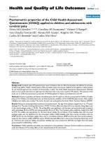
the samples are studied by scanning electron microscopy
(SEM) technique. SEM images are shown in Fig. 1a–c,
where we also present the schematics of device structure
(Fig. 1d).
Results and Discussion
I–V characteristics are measured using a Keithley 238
source meter. The samples are placed on a copper base
from backside; a metallic sharp tip (D = 0.5 mm) is used
as top contact to the NWs/PMMA array. The energy con-
version efficiency is determined by illuminating the
Fig. 1 SEM images taken at
different stages of device
structure preparation. a As
grown GaAs NWs array, b after
PMMA deposition, c top view
of the resulting structure (after
oxygen plasma treatment),
d schematic view of the device
structure testing
Nanoscale Res Lett (2010) 5:360–363 361
123
structures using a halogen arc-lamp with the calibrated
power density of P = 100 mW/cm
2
.
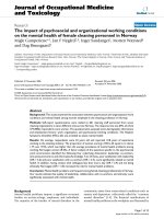
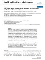
Figure 2a shows typical current density–voltage (J–V)
characteristic of the device structure measured in dark. The
fabricated cells exhibit a clear diode behavior. Under the
forward bias, a turn on of the device is observed at 0.7 V.
At ?0.5 V bias, the forward current density is varied
within the range of 1.2–5.5 mA/cm
2
, while the reverse
leakage current density is typically about 0.01 mA/cm
2
at
-0.5 V. The rectification ratio is therefore greater than 10
2
at ± 0.5 V, which demonstrates a reasonable p–n junction
between the p-type GaAs NWs and n-type GaAs(111)B
substrate.
The fill factor (FF) and the power conversion efficiency
(g) are calculated according to the following equations:
FF ¼ðV
M
J
M
Þ=ðV
OC
J
SC
Þ; ð1Þ
g ¼ V
M
J
M
=P; ð2Þ
where V
OC
and J
SC
are the open-circuit voltage and the
short-circuit current; V
M
and J
M
are the voltage and the
current density at the maximum power output, respectively,
and P is the incident optical power density from the lamp.
In Fig. 2b, we present the J–V characteristics of the best
sample (with the highest NWs) in dark and under illumi-
nation. Upon illumination of the front surface with the
light, the structure yields an obvious photocurrent. The
short-circuit current density J
SC
equals 27.4 mA/cm
2
, and
the open-circuit voltage V
OC
amounts to 0.245 V. This
corresponds to the conversion efficiency of 1.65% and the
fill factor of 25%.
In Table 1, we summarize the conversion efficiency for
different NW morphology. It is seen that the substrate
temperature variation even within the range of 60° leads to
significant (up to 20 times) change in the conversation
efficiency. The morphology of NW arrays therefore
strongly influences the device properties. This should be
due to geometrical factors as well as different Be
incorporation processes at different temperatures (resulting
in variable doping concentration profiles). Previously, it
has been shown that the substrate temperature *550 °Cis
optimal for MBE growth of GaAs NWs at the GaAs growth
rate of 1 ML/s [21, 22]. At this temperature, GaAs NWs
exhibit better homogeneity as well as the highest NW/2D
growth rate ratio. When the temperature is above or below
this optimal value, a rapid decrease in the NW height is
observed, which is consistent with the results of previous
studies [21, 22]. We also observe the decrease in surface
density as the temperature is increased to 580 °C, which
can also affect the conversion efficiency. The lowest
efficiency corresponds to the sample grown at lowest
temperature of 520 °C, although its morphological char-
acteristics are similar to other samples. Most probably, at
this temperature, Be atoms incorporate in different sub-
lattice site leading to a higher compensation level. All
above mentioned factors could influence significantly the
quality of device structures. For example, the results of
Ref. [18] show that the substrate temperature variation of
20° (due to the inhomogeneity of the substrate heater)
could change the conversion efficiency by the factor of 5.5,
which is also in agreement with our study. Additionally,
electrical properties of the device structures (V
OC
and J
SC
)
still have to be optimized. In particular, for GaAs material
we could expect higher open-circuit voltage. Two possible
reasons may influence on relatively low V
OC
. First, the
-1,5 -1,0 -0,5 0,0 0,5 1,0 1,5
-5
0
5
10
15
20
25
30
35
J, mA/cm
2
J, mA/cm
2
U, Volts
-0,1 0,0 0,1 0,2 0,3
-40
-30
-20
-10
0
10
U, Volts
dark
illuminated
(a) (b)
Fig. 2 a J–V characteristic of the device structure measured in dark, b J–V characteristics in dark and under illumination with an intensity of
100 mW/cm
2
Table 1 Morphological characteristics and conversion efficiencies of
different samples
T
s
(°C)
NWs surface density
(cm
-2
)
NWs height
(lm)
Conversion
efficiency (%)
520 1 9 10
9
1.7 0.08
535 1 9 10
9
1.9 0.27
550 1 9 10
9
2.2 1.65
580 5 9 10
8
1.7 0.29
362 Nanoscale Res Lett (2010) 5:360–363
123
parasitic two-dimensional layer is formed between the
NWs and an additional p–n junction is created. Second, Be
adatoms may segregate on the NW sidewalls forming
depletion regions inside the NWs. Moreover, the fill factor
FF (*25%) is also rather low. Further optimization may
include the study of Be doping level influence on V
OC
and
J
SC
. A heterostructured scheme may be considered in order
to increase V
OC
(e.g., GaAs/AlGaAs core–shell structures).
To conclude, we have investigated the PV properties of
p-doped GaAs NWs array grown on the n-GaAs(111)B
substrate at different substrate temperatures. The highest
conversation efficiency 1.65% is achieved at 550 °C. To
the best of our knowledge, this is the highest value
obtained for the GaAs-based NW arrays.
Acknowledgments The authors are grateful to the financial support
received from RFBR grants, scientific grant of St Petersburg Scien-
tific Centre and different scientific programs of RAS. The authors
wish to thank Dr. O. Bratenshtain for helpful discussions and pro-
viding measurement set-up.
References
1. M.H. Huang, S. Mao, H. Feick, H. Yan, Y. Wu, H. Kind,
E. Webber, R. Russo, P. Yang, Science 292, 1897 (2001)
2. P. Yang, H. Yan, S. Mao, R. Russo, J. Johnson, R. Saykally,
N. Morris, J. Pham, R. He, H. Choi, J. Adv. Funct. Mater. 12, 323
(2002)
3. H. Ng, J. Han, T. Yamada, P. Nguyen, Y.P. Chen, M. Meyyap-
pan, Nano Lett. 4, 1247 (2004)
4. H.M. Kim, Y.H. Cho, H. Lee, S. Kim, S.R. Ryu, D.Y. Kim,
T.W. Kang, K.S. Chung, Nano Lett. 4, 1059 (2004)
5. X.D. Wang, C.J. Summers, Z.L. Wang, Nano Lett. 4, 423 (2004)
6. W.B. Choi, J.U. Chu, K.S. Jeong, E.J. Bae, J.W. Lee, J.J. Kim,
J.O. Lee, Appl. Phys. Lett. 79, 3696 (2001)
7. Y.B. Tang, H.T. Cong, Z.M. Wang, H.M. Cheng, Appl. Phys.
Lett. 89, 253112 (2006)
8. A.B.F. Martinson, J.W. Elam, J.T. Hupp, M.J. Pellin, Nano Lett.
7, 2183 (2007)
9. C.Y. Jiang, X.W. Sun, G.Q. Lo, D.L. Kwong, J.X. Wang, Appl.
Phys. Lett. 90, 263501 (2007)
10. Y J. Lee, D.S. Ruby, D.W. Peters, B.B. McKenzie, J.W. P. Hsu,
Nano Lett. v.8, 1501 (2008)
11. L. Hu, G. Chen, Nano Lett. 7, 3249 (2007)
12. F. Glas, Phys. Rev. B 74, 121302 (2006)
13. R.S. Wagner, W.C. Ellis, Appl. Phys. Lett. 4, 89 (1964)
14. V.G. Dubrovskii, G.E. Cirlin, I.P. Soshnikov, A.A. Tonkikh, N.V.
Sibirev, Y.B. Samsonenko, V.M. Ustinov, Phys. Rev. B
71, 205325 (2005)
15. L. Schubert, P. Werner, N.D. Zakharov, G. Gerth, F.M. Kolb, L.
Long, U. Goesele, T.Y. Tan, Appl. Phys. Lett. 84, 4968 (2004)
16. Y.B. Samsonenko, G.E. Cirlin, V.A. Egorov, N.K. Polyakov,
V.P. Ulin, V.G. Dubrovskii, Semiconductors 42, 1445 (2008)
17. B. Tian, T.J. Kempa, C.M. Lieber, Chem. Soc. Rev. 38, 16 (2009)
18. J.A. Czaban, D.A. Thompson, R.R. LaPierre, Nano Lett. 9, 148
(2009)
19. C. Colombo, M. Heiss, M. Gra
¨
tzel, A. Fontcuberta i Morral,
Appl. Phys. Lett. 94, 173108 (2009)
20. W. Wei, X Y. Bao, C. Soci, Y. Ding, Z L. Wang, D. Wang,
Nano Lett. 9, 2926 (2009)
21. J.C. Harmand, M. Tchernycheva, G. Patriarche, L. Travers,
F. Glas, G. Cirlin, J. Cryst. Growth 301–302, 853 (2007)
22. V.G. Dubrovskii, N.V. Sibirev, R.A. Suris, G.E. Cirlin,
J.C. Harmand, V.M. Ustinov, Surf. Sci. 601, 4395 (2007)
Nanoscale Res Lett (2010) 5:360–363 363
123