Báo cáo hóa học: " Research Article A Low-Complexity LMMSE Channel Estimation Method for OFDM-Based Cooperative Diversity Systems with Multiple Amplify-and-Forward Relays" docx
Bạn đang xem bản rút gọn của tài liệu. Xem và tải ngay bản đầy đủ của tài liệu tại đây (713.4 KB, 9 trang )
Hindawi Publishing Corporation
EURASIP Journal on Wireless Communications and Networking
Volume 2008, Article ID 149803, 9 pages
doi:10.1155/2008/149803
Research Article
A Low-Complexity LMMSE Channel Estimation Method
for OFDM-Based Cooperative Diversity Systems with
Multiple Amplify-and-Forward Relays
Kai Yan, Sheng Ding, Yunzhou Qiu, Yingguan Wang, and Haitao Liu
Shanghai Institute of Microsystem and Information Technology, Chinese Academy of Sciences, Road ChangNing 865,
Shanghai 200050, China
Correspondence should be addressed to Kai Yan,
Received 20 January 2008; Accepted 18 May 2008
Recommended by George Karagiannidis
Orthogonal frequency division multiplexing- (OFDM-) based amplify-and-forward (AF) cooperative communication is an
effective way for single-antenna systems to exploit the spatial diversity gains in frequency-selective fading channels, but the
receiver usually requires the knowledge of the channel state information to recover the transmitted signals. In this paper, a
training-sequences-aided linear minimum mean square error (LMMSE) channel estimation method is proposed for OFDM-
based cooperative diversity systems with multiple AF relays over frequency-selective fading channels. The mean square error
(MSE) bound on the proposed method is derived and the optimal training scheme with respect to this bound is also given. By
exploiting the optimal training scheme, an optimal low-rank LMMSE channel estimator is introduced to reduce the computational
complexity of the proposed method via singular value decomposition. Furthermore, the Chu sequence is employed as the training
sequence to implement the optimal training scheme with easy realization at the source terminal and reduced computational
complexity at the relay terminals. The performance of the proposed low-complexity channel estimation method and the
superiority of the derived optimal training scheme are verified through simulation results.
Copyright © 2008 Kai Yan et al. This is an open access article distributed under the Creative Commons Attribution License, which
permits unrestricted use, distribution, and reproduction in any medium, provided the original work is properly cited.
1. INTRODUCTION
Multiple-input multiple-output (MIMO) wireless commu-
nication systems have attracted considerable interest in the
last few years for their advantages in improving the link
reliability, as well as increasing the channel capacity [1, 2].
Unfortunately, it is not practical to equip multiple antennas
at some terminals in wireless networks due to the cost and
size limits. To overcome these limitations, the concept of
cooperative diversity has been recently proposed for single-
antenna systems to exploit the spatial diversity gains in
wireless channels [3–6]. Utilizing the broadcasting nature
of radio waves, the source terminal can cooperate with the
relay terminals in information transport. In this manner, the
spatial diversity gains can be obtained even when a local
antenna array is not available.
Currently, several cooperative transmission protocols
have been proposed and can be categorized into two
principal classes: the amplify-and-forward (AF) scheme and
the decode-and-forward (DF) scheme. In the AF scheme,
the relay terminals amplify the signals from the source
terminal and forward them to the destination terminal.
In the DF scheme, the relay terminals first decode their
received signals and then forward them to the destination
terminal. Compared with the DF scheme, the AF scheme is
more attractive for its low complexity since the cooperative
terminals do not need to decode their received signals.
Hence, we focus our attention on the AF relay scheme in this
paper.
To take the advantages that cooperative transmission
can offer, accurate channel state information (CSI) is
usually required at the relay and/or destination terminal.
For example, if distributed space-time coding (DSTC) is
applied at the relays, then the accuracy of CSI of all links
at the destination terminal is crucial for the improvement
of the system performance. The training-sequences-aided
method is one of the most widely used approaches to learn
the channel in wireless communication systems due to its
2 EURASIP Journal on Wireless Communications and Networking
simplicity and reliability [7]. However, there have been only
a few literatures on training-based AF channel estimation,
and research in this area is still in its infancy. Based on the
assumption of flat-fading channels, [8, 9] propose training-
sequences-aided least square (LS) and linear minimum mean
square error (LMMSE) channel estimators for single-relay-
assisted cooperative diversity systems in cellular networks.
In [10, 11], minimum variance unbiased (MVU) and LS
channel estimators are introduced respectively for orthogo-
nal frequency division multiplexing (OFDM-) based single-
relay-assisted cooperative diversity systems over frequency-
selective fading channels. The channel estimators developed
in these literatures only consider the single-relay-assisted
cooperative communication scenario. Training designs that
are optimal in the scenarios of multiple-relays-assisted
cooperative communication have drawn relatively little
attention. It was investigated for the case of multiple-relays-
assisted AF cooperative networks over frequency-flat fading
channels in [12] using the channel estimation performance
bound as a metric for training design. It was found that
the optimal training can be achieved from an arbitrary
sequence and a set of well-designed precoding matrices for
all relays. In this study, we are interested in the broadband
cooperative communication scenarios, for example, the real-
time video surveillance application in distributed sensor
networks [13]. As the broadband applications demand high-
speed data transmission, the frequency-flat channels become
time-dispersive when the transmission bandwidth increases
beyond the coherence bandwidth of the channels. Thus, how
to obtain the accurate CSI in a low-complexity manner for
multiple AF-relays-assisted broadband cooperative diversity
systems could be a challenge problem and has not been
satisfactorily addressed, which motivates our present work.
In this paper, we propose a training-sequences-aided
LMMSE channel estimation method for OFDM-based
cooperative diversity systems with multiple AF relays over
frequency-selective block-fading channels. First, the mean
square error (MSE) bound on the proposed method is
computed. Then, the optimal training scheme with respect to
this bound is derived. By exploiting the inherent orthogonal
characteristic of the optimal training scheme, we utilize the
optimal training sequence as the singular vector to decom-
pose the channel correlation matrix and then introduce an
optimal low-rank channel estimator based on singular value
decomposition (SVD) [14, 15]. Since we avoid the matrix
inverse operation, the computational complexity at the
destination terminal is reduced significantly. Furthermore,
the Chu sequence is employed as the training sequence at
the source terminal to achieve the minimum MSE estimation
performance while avoid the complex matrix multiplication
operation at the relay terminals. Simulation results verify
the performance of the low-complexity channel estimation
method in the multiple AF relays-assisted broadband coop-
erative communication scenario. And the superiority of the
derived optimal training scheme is also confirmed.
This paper is organized as follows. Section 2 describes
the channel and system model. We introduce the low-
complexity LMMSE channel estimation method in Section 3.
In Section 4, we design the optimal training scheme. Simula-
SD
h
SR1
h
SR2
h
SRN
h
R1D
h
R2D
h
RND
R
1
R
2
R
N
.
.
.
The first time slot
The second time slot
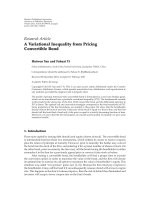
Figure 1: Multiple AF-relays-assisted cooperative diversity systems.
tion results and discussions are given in Section 5, followed
by our conclusions in Section 6.
Notations
(·)
−1
,(·)
T
,(·)
H
,(·)
N
, ,and⊗ denote inverse, transpose,
Hermitian transpose, modulo-N, element-wise production,
and convolution operation, respectively. diag(x) stands for
a diagonal matrix with x on its diagonal.
K denotes
an arbitrary nonminus integer less than K. E[
·]denotes
expectation, tr[
·] denotes the trace of a matrix, [·]
k
denotes
the kthentryofavector.I
K
denotes the identity matrix of
size K,and0
m×n
denotes all-zero matrix of size m × n.Bold
uppercase letters denote matrices and bold lower-case letters
denote vectors.
2. CHANNEL AND SYSTEM MODEL
2.1. Channel model
As shown in Figure 1, the wireless cooperative diversity sys-
tems we consider consist of N + 2 terminals which are placed
randomly. We assume that all the terminals are equipped
with only one antenna and work in the half-duplex mode,
that is, they cannot receive and transmit simultaneously.
Introduce the variables, ρ
SRi
, i ∈ (
1 ···N
), ρ
RiD
,andρ
SD
,
to depict the large-scale path loss of the links S
→R
i
, R
i
→D,
and S
→D.LetG
SRi
= ρ
SRi
/ρ
SD
and G
RiD
= ρ
RiD
/ρ
SD
be
the geometric gains of the link S
→R
i
and R
i
→D relative to
the direct transmission link S
→D. The small-scale channel
impulse response of each wireless link l is modeled as a
tapped delay line with tap spacing equal to the sample
duration t
s
:
h
l
(t)=
R
l
−1
r=0
h
r
l
(t)δ
t−rt
s
, l =SRi, RiD, i∈(
1 ···N
),
(1)
where R
l
represents the number of resolvable paths for the
link l and h
r
l
denotes the channel gain of the path r of the
link l. h
r
l
is described by a zero-mean complex Gaussian
random process, which is independent for different paths
Kai Yan et al. 3
with variance σ
2
r,l
. We normalize the channel by letting
R
l
r=0
σ
2
r,l
= 1. Denote the R
l
× 1 channel power vector of link
l as σ
2
l
. Since the spacing between each terminal is generally
larger than the coherent distance, all the signals transmitted
from different terminals and received at different terminals
are assumed to undergo independent fades. We assume that
the channel h
l
remains constant over the transmission of a
frame but varies independently from frame to frame, and
then drop the time index for brevity in the following sections.
2.2. System model
In this paper, a simple bandwidth-efficient two-hop AF
protocol is adopted for communications in the cooperation
systems. Specifically, the source terminal S broadcasts the
blockwise information to the N relay terminals R
i
,where
i
= 1, , N, in the first time slot. Then these relays perform
DSTC via multiplying their received blockwise signals with
local matrix and forward the coded signals to the destination
terminal D simultaneously in the second time slot [16–20].
Since the channel between terminal S and terminal D is
the conventional single-input single-output (SISO) one and
can be separately estimated in the first time slot, the direct
transmission link S
→D is omitted in our discussion. Later,
it will be shown that the training sequence employed by this
channel estimation method can also achieve the optimal esti-
mation performance for this direct SISO link. For combating
the intersymbol interference from multipath channels, cyclic
prefixes (CPs) at the source terminal and relay terminals are
added to the information and the length of CPs should be
more than the maximum number of multipath to undergo in
each time slot. As OFDM can turn frequency-selective fading
channel into several parallel frequency-flat ones, cooperative
communication in time-dispersive channels is applicable by
extending some DSTC methods, for example, the work in
[20], to corresponding subcarriers at each relay in a form
of OFDM symbol blockwise transmission. Since multiplying
OFDM symbol in the time domain is equal to multiplying
each subcarrier in the frequency domain, the requirement
of DFT and IDFT operation at the relay terminals can be
relaxed. Then terminal D requires the knowledge of channel
frequency responses of N concatenation links, S
→R
i
→D, i =
1, , N, to decode the received signals. Equivalently in the
time domain, terminal D needs to know h
SRi
⊗ h
RiD
,where
i
= 1, , N, which will be discussed in the next section.
3. LOW-COMPLEXITY LMMSE CHANNEL
ESTIMATION METHOD
3.1. LMMSE channel estimation method
This subsection proposes a training-based method for chan-
nel estimation of multiple AF-relays-assisted cooperative
diversity systems in the simple bandwidth-efficient two-hop
protocol. Suppose the time-domain training sequence with
unit power, which is transmitted from the source terminal S
in the first time slot, is denoted by the K
×1vectorx
0
.Before
transmission, this vector is preceded by a CP with length
μ
CP1
. We assume that μ
CP1
≥ max(R
SRi
), where i = 1, , N.
After removing the CP, the received K
× 1vectorbyrelay
terminal R
i
can be written as
r
Ri
= H
SRi
x
0
ρ
SRi
+ n
Ri
,(2)
where H
SRi
is a circulant matrix with the first column
given by [h
T
SRi
0
1×(K−R
SRi
)
]
T
; n
Ri
is the complex additive white
Gaussian noise (AWGN) at terminal R
i
with zero-mean and
variance σ
2
n
. As performing DSTC in the data transmission
section, terminal R
i
is also assumed to forward a linear
function of its received signal vector in the training section
that is given by
y
Ri
= M
i
r
Ri
α
i
,(3)
where M
i
is a K ×K linear transformation unitary matrix to
ensure channel identifiable, as explained later; α
i
is the relay
amplification factor to meet the power constraint for each
relay terminal and is given by
α
i
=
p
i
ρ
SRi
+ σ
2
n
,(4)
where P
i
is the transmission power at terminal R
i
.The
factor α
i
considered in this paper does not depend on the
instantaneous channel realization [21, 22], thus no channel
estimation is required at the relay terminals. In the second
time slot, each relay terminal appends a CP with length
μ
CP2
to y
Ri
and transmits it to the destination terminal D.
It is assumed that μ
CP2
≥ max(R
RiD
), where i = 1, , N.
Terminal D collects signals from N relay terminals, and the
received K
×1 vector after removing the CP can be written as
y
D
=
N
i=1
H
RiD
y
Ri
ρ
RiD
+ n
D
=
N
i=1
H
RiD
M
i
H
SRi
x
0
ρ
SRi
ρ
RiD
α
i
+
N
i=1
H
RiD
M
i
n
Ri
ρ
RiD
α
i
+ n
D
,
(5)
where H
RiD
is a circulant matrix with the first column
given by [
h
T
RiD
0
1×(K-R
RiD
)
]
T
; n
D
is the complex AWGN at
terminal D with zero-mean and variance σ
2
n
. Introduce the
variable N
i
= H
−1
SRi
M
i
H
SRi
and let x
i
= N
i
x
0
√
ρ
SRi
ρ
RiD
α
i
be
the training sequence of terminal R
i
. Then, (5)becomes
y
D
=
N
i=1
H
RiD
H
SRi
x
i
+
N
i=1
H
RiD
M
i
n
Ri
ρ
RiD
α
i
+ n
D
=
N
i=1
H
SRiD
x
i
+ n,
(6)
where H
SRiD
is a circulant matrix with the first column given
by [
(h
SRi
⊗ h
RiD
)
T
0
1×(K−R
SRi
−R
RiD
+1)
]
T
; the effective noise
term
N
i
=1
H
RiD
M
i
n
Ri
G
RiD
α
i
+ n
D
is denoted by n.Denote
the K
× (R
SRi
+R
RiD
−1) circulant training matrix of terminal
4 EURASIP Journal on Wireless Communications and Networking
R
i
as X
i
whose first column is equal to x
i
, then (6)canbe
rewritten as
y
D
= Xh + n,(7)
where X
= [X
1
···X
N
]andh = [(h
SR1
⊗ h
R1D
)
T
···(h
SRN
⊗ h
RND
)
T
]
T
.
Note that, the channel vector h is identifiable if and only
if X has full column rank, which occurs when
K
≥
N
i=1
R
SRi
+ R
RiD
− N. (8)
If terminal R
i
only forwards a untransformed version of its
received signals, or equivalently M
i
= I
K
, the columns of
X are in proportion which would cause the column rank
of X deficient and then channel vector h is unidentifiable.
Consequently, the unitary transformation matrix M
i
is
necessary for each relay terminal in the training section.
This explains those channel estimators in [10, 11] designed
for broadband AF cooperative communication cannot be
extended straightforwardly to the multiple relays scenario in
the two-hop protocol.
Each concatenation channel h
SRi
⊗ h
RiD
,wherei =
1, , N,hasR
SRi
+ R
RiD
− 1 taps. Denote the channel tap
number of all concatenation links
N
i
=1
(R
SRi
+ R
RiD
) − N as
T.Itisfoundfrom(8) that the training length should not be
less than the channel tap number of all concatenation links;
otherwise, the channel vector h would be unidentifiable. On
the other hand, given a specific training length K,wecan
use (8) to determine the maximum relay number N that this
channel estimator can supply.
The simplest algorithm for the channel estimation using
(7) is the LS estimator, which does not exploit a priori
knowledge of channel statistics and noise power and has
worse estimation performance relative to the MMSE esti-
mator. However, it is intractable to perform MMSE channel
estimation for the AF channel because the total channel
h is non-Gaussian. Therefore, we focus our attention on
the suboptimal LMMSE channel estimator. The analysis
and simulation results shown in later sections indicate that
our low-complexity channel estimation method provides
satisfactory performance.
Exploiting the noncorrelation property of channels of a
different link l, we can obtain the autocorrelation matrix of
the channel vector h:
C
h
= E
hh
H
= diag
σ
2
SR1
⊗ σ
2
R1D
··· σ
2
SRN
⊗ σ
2
RND
.
(9)
We assume that the relative distances among all terminals are
far enough to ensure local noise n
Ri
and n
D
to be uncor-
related. Using M
i
M
H
i
= I
K
, the statistical autocorrelation
matrix of the effective noise term n can be written as
C
n
= E
nn
H
=
N
i=1
ρ
RiD
α
2
i
E
H
RiD
H
H
RiD
+ I
K
σ
2
n
. (10)
Since h
r
RiD
are assumed to be uncorrelated for different paths
r
∈ [1 ···R
RiD
], we can obtain
E
H
RiD
H
H
RiD
= I
K
. (11)
By substituting (11) into (10), the statistical C
n
can be
rewritten as
C
n
= E
nn
H
=
N
i=1
ρ
RiD
α
2
i
+1
σ
2
n
I
K
. (12)
The autocorrelation matrix of a received signal y
D
is
C
y
D
= E
y
D
y
H
D
=
XC
h
X
H
+ C
n
. (13)
Based on the LMMSE criterion [23], the estimated channel
can be written as
h = C
h
X
H
C
−1
y
D
y
D
. (14)
And the autocorrelation matrix of estimation error is
C
e
= E
ee
H
=
C
−1
h
+ X
H
C
−1
n
X
−1
. (15)
When C
h
is rank deficient, a small value can be added to the
diagonal of C
h
. Therefore, the average MSE of the LMMSE
channel estimator can be represented as
J
e
=
1
N
i=1
R
SRi
+ R
RiD
−
N
tr
C
e
=
1
N
i=1
R
SRi
+ R
RiD
− N
tr
C
−1
h
+ X
H
C
−1
n
X
−1
.
(16)
Lemma 1. For positive definite M
× M matrix A with its mth
diagonal element given by a
m
, the following inequality holds:
tr
A
−1
≥
M
m=1
1
a
m
, (17)
where equality holds if and only if A is diagonal.
Proof (see [23, page 65]). Based on this lemma, the mini-
mum of (16) is achieved if and only if X
H
X is diagonal.
Therefore, the optimal training scheme is
X
H
i
X
i
= ρ
SRi
ρ
RiD
α
2
i
KI
(R
SRi
+R
RiD
−1)
∀i ∈ (1, , N)
X
H
m
X
n
= 0
(R
SRm
+R
RmD
−1)×(R
SRn
+R
RnD
−1)
∀m, n ∈ (1, , N),
with m
/
= n.
(18)
By substituting (9), (12), and (18) into (16), we obtain the
MSE bound of this channel estimation method
J
e
=
1
T
N
i=1
R
SRi
+R
RiD
−1
j=1
×
σ
2
SRi
⊗ σ
2
RiD
−1
j
+
ρ
SRi
ρ
RiD
α
2
i
K
(
N
i=1
ρ
RiD
α
2
i
+1)σ
2
n
−1
.
(19)
Kai Yan et al. 5
3.2. Low-complexity LMMSE channel estimator
The LMMSE channel estimator (14) is of considerable
complexity since a matrix inversion is involved. To simplify
this estimator, we exploit the optimal training scheme (18)
to get an optimal low-complexity LMMSE channel estimator
based on SVD in this subsection [14, 15].
Lemma 2. If V
1
∈ C
n×r
has orthonormal columns, then there
exists V
2
∈ C
n×(n−r)
such that V = [V
1
V
2
] is orthogonal.
Proof (see [24, page 69]). Based on this lemma, there exists
K
× (K − T)matrixW to make K × K matrix U = [X W]
ensure U
H
U = diag(μ), because the training matrix X shown
in (18) has orthonormal columns. Denote the diagonal entry
of X
H
X, C
h
,andC
n
as ε, α,andγ. Introduce the K ×1vector
β
= [α 0
1,(K−T)
]. Then, the Hermitian matrix XC
h
X
H
can be
rewritten as
XC
h
X
H
= Udiag(β)U
H
= Fdiag(
μ)diag(β)diag(
μ)F
H
= Fdiag(μ β)F
H
,
(20)
where F is a unitary matrix from U. Substituting (20) into
C
−1
y
D
yields
C
−1
y
D
=
Fdiag(μ β)F
H
+ Fdiag(γ)F
H
−1
= Fdiag
(μ β + γ)
−1
F
H
.
(21)
Lemma 3. Using (20) and (21), LMMSE channel estimator
(14) can be rewritten as
h = diag
α
ε α +[γ]
1:T
X
H
y
D
. (22)
Proof. See the appendix.
Since the optimal low-rank LMMSE channel estimator
(22) avoids the matrix inverse calculation, the computation
complexity is significantly reduced compared with (14).
Building upon a similar deduction of minimizing MSE, we
find condition (18) is also the optimal training scheme for
LS channel estimator. Thus, we can see that the performance
of the LMMSE channel estimator (22) is equal to the
Wiener-filtered LS channel estimator. When the second-
order channel statistics α and the noise power γ are not
available at the destination terminal, we can resort to the
LS channel estimator to obtain initial channel estimates and
then use these estimates to estimate α and γ.
4. OPTIMAL TRAINING
4.1. Design of the optimal training scheme
In this subsection, we employ the Chu sequence to imple-
ment the optimal training scheme (18). The Chu sequence
is a kind of perfect N-phase sequences which have a
constant magnitude in both the time domain and the fre-
quency domain [25]. The constant time-domain magnitude
property of the Chu sequence precludes peak-to-average
power ratio (PAPR) problem in implementation while the
constant frequency-domain magnitude property makes the
Chu sequence invaluable in the design of the optimal training
scheme of many communication systems. A length-K Chu
sequence is defined as
x(k)
=
⎧
⎨
⎩
e
jπlk
2
/K
,forevenK,
e
jπlk(k+1)/K
,foroddK,
(23)
where k
∈ (0, , K − 1) and l are relatively prime to K.It
should be noted that the Chu sequence can be realized with
compact direct digital synthesis (DDS) devices.
To implement the optimal training scheme (18), a
length-K Chu sequence is employed by the source terminal S
as the training sequence x
0
. Terminal S appends a length-μ
CP1
CP to x
0
and then broadcasts it to N-relay terminals in the
first hop. Define a K
× 1vectorm
i
,wherei = 2, , N,with
the
i−1
j=1
(R
SRj
+R
RjD
−1)+1
th
entrytobe1andotherentries
to be 0. Let M
i
,wherei = 2, , N, be a circulant matrix with
the first column to be m
i
and let M
1
be I
K
. After discarding
CP, terminal R
i
,wherei = 1, , N, multiplies their received
signal vectors with local unitary matrix M
i
to get the signal
vector y
Ri
. Then, these relay terminals forward their signal
vectors y
Ri
preceded with length-μ
CP2
CPs to the destination
terminal D simultaneously in the next hop. Finally, terminal
D receives signal vector y
D
after removing the CP and obtains
CSI via the low-complexity LMMSE channel estimator (22).
4.2. Optimality of the proposed training scheme
This subsection will prove the optimality of the training
scheme proposed in the last subsection. For the direct SISO
link S
→D, the Chu sequence employed by this training
scheme can achieve the optimal estimation performance in
the first time slot, owing to its constant magnitude in the
frequency domain. In the following, the optimality for the
concatenation links will be proved.
Since both H
SRi
and M
i
,wherei = 1, , N, are circulant
matrices, the following relation holds:
M
i
H
SRi
= H
SRi
M
i
. (24)
With this relation, the training sequence x
i
of terminal R
i
can
be rewritten as
x
i
= M
i
x
0
ρ
SRi
ρ
RiD
α
i
. (25)
Using M
i
M
H
i
= I
K
and perfect impulse-like autocorrelation
property of x
0
, to prove that x
i
satisfies the first condition of
(18)isstraightforward.TheproposedM
i
ensures that x
m
(k)
and x
n
((k −R
SRn
+ R
RnD
− 1)
K
) are orthogonal, and x
n
(k)
and x
m
((k −R
SRm
+ R
RmD
− 1)
K
) are orthogonal, where
k
= 0, , K − 1, m, n = 1, , N,andm
/
= n. Thus, the
second condition of (18) can be satisfied. Besides, according
to the definition of M
i
and the above discussion, to make sure
6 EURASIP Journal on Wireless Communications and Networking
10
−6
10
−5
10
−4
10
−3
10
−2
MSE
0 5 10 15 20 25 30 35
SNR (dB)
G
sr
= 0dBG
rd
= 0dB
G
sr
= 5dBG
rd
= 0dB
G
sr
= 10 dB G
rd
= 0dB
G
sr
= 15 dB G
rd
= 0dB
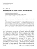
Figure 2: Impact of geometric gains on the MSE performance.
that M
i
exists for all relay terminals, the following inequality
is required for the extreme case m
= 1, n = N or m =
N, n = 1:
N−1
j=1
R
SRj
+ R
RjD
− 1
+1≤ K +1−
R
SRN
+ R
RND
− 1
(26)
which is equivalent to (8). Therefore, under the premise that
h is identifiable, M
i
exist for all relays. Moreover, since the
Chu sequence exists for any finite length, we conclude that
for any finite number of total channel taps T, this training
scheme can always achieve the minimum MSE estimation
performance.
5. SIMULATION RESULTS AND DISCUSSION
5.1. System parameters
The performance of the proposed LMMSE channel esti-
mation method and the superiority of the derived optimal
training scheme in the multiple AF-relays-assisted cooper-
ative communication scenario are evaluated by computer
simulations. We consider an OFDM cooperation system
where each relay terminal utilizes the coding method as in
[20] to perform DSTC in data transmission section. This
type of DSTC is chosen because it obtains the optimal
diversity-multiplexing gain (D-MG) performance of the
considered orthogonal AF protocol, but other types of DSTC
are also applicable since we are only interested in the
performance of the proposed channel estimation method.
The modulation mode is set 4-QAM and the maximum-
likelihood decoder is applied for each subcarrier at the
destination terminal. The MSE bound of the proposed
channel estimation method shown in (19) is related with
the power delay profile of the channel, thus it varies
with different channel models. However, to verify that our
optimal training scheme indeed attains the MSE bound
deduced in theory, selecting a typical channel model through
the Monte Carlo simulation is enough. Here, the typical
urban (TU) twelve-path channel model [26], which is
widely used in the community, is adopted to generate
the multipath Rayleigh fading channels between each two
terminals. The power delay profile of the channel model
is set with tap mean power
−4, −3, 0, −2, −3, −5,
−7, −5, −6, −9, −11, and −10 dB at tap delays 0.0,
0.2, 0.4, 0.6, 0.8, 1.2, 1.4, 1.8, 2.4, 3.0, 3.2, and 5.0 μs.
The entire channel bandwidth is 5 MHz and is divided
into 256 tones. CPs of 6.4- μs duration are appended in
source terminal and relay terminals to eliminate the effect
of multipath fading. Perfect synchronization among relay
terminals is assumed to observe the channel estimation
performance alone. The transmission power at the source
terminal is normalized to unity. The unitary matrices M
i
of relay terminals in the training section, mentioned in
Section 4, are adopted to ensure channel identifiable in the
simulation.
5.2. Simulation results
Figure 3 illustrates the MSE of the proposed LMMSE channel
estimation method for different numbers of relay terminals
when both length-256 Chu and random sequences are
used. To observe the effect of the number of relays on the
MSE and bit error rate (BER) performance alone, these
relays are assumed to be distributed in a symmetrical way,
for example, the geometric gains G
SRi
and G
RiD
for all
relays are set 5 dB and 0 dB, respectively. The effect of the
geometric gains on the MSE performance will be shown
later. The unit transmission power in the second hop is
equally divided among these relays. In the case of the
unequal geometric gains, the Matlab function “fmincon”
can be used for optimizing the power allocation of these
relay terminals with respect to the MSE bound given by
(19). Figure 3 also illustrates the MSE bound. We can see
that the optimal training scheme mentioned in Section 4
indeed attains the MSE bound and outperforms substantially
random training sequences. Besides, the MSE bound is below
10
−3
in moderate to high SNR (10 ∼35 dB), indicating good
channel estimation performance.
Figure 4 plots the BER performance corresponding to the
length-256 optimal and suboptimal training schemes when
different numbers of relays are employed. As expected from
the MSE performance comparison results, a substantial BER
performance gain of the optimal training scheme over the
suboptimaloneisobserved.TheBERperformanceofperfect
CSI is also given as a benchmark. From the figure, we can see
that the BER performance of the optimal training scheme
is very close to the perfect CSI case when only two relays
are employed, which confirms the accuracy of the proposed
channel estimation method, while the performance gap
increases when another two relays are involved. This can
be explained by the fact depicted in Figure 3 that the MSE
performance decreases as the number of relays increases.
However, since spatial diversity is dominant in the BER
performance relative to the channel estimation error, four
Kai Yan et al. 7
10
−6
10
−5
10
−4
10
−3
10
−2
10
−1
MSE
0 5 10 15 20 25 30 35
SNR (dB)
N
= 2bound
N
= 2Chu
N
= 2random
N
= 4bound
N
= 4Chu
N
= 4random
Figure 3: MSE performance comparison of the proposed channel
estimation method using different training sequences.
10
−4
10
−3
10
−2
10
−1
10
0
BER
0 5 10 15 20 25 30 35
SNR (dB)
Perfect
Chu
Random
N
= 4
N
= 2
Figure 4: BER performance comparison of the proposed channel
estimation method using different training sequences.
relays provide better BER performance than two relays in
moderate to high SNR (10
∼35 dB).
Figure 5 displays the impact of the relay number on the
MSE performance of the length-256 and length-512 optimal
training. Note that the longer training sequences lead to the
higher MSE performance for the same relay number. This
is expected from (19) since the transmitting energy in the
training section is linear with the training length K.From
this figure, it is seen that increasing the relay number would
degrade the MSE performance though the training energy
in the cooperation system remains the same. This is because
the apportioned training energy for each relay decreases
10
−6
10
−5
10
−4
10
−3
10
−2
10
−1
MSE
0 5 10 15 20 25 30 35
SNR (dB)
K
= 256 N = 4
K
= 256 N = 5
K
= 256 N = 6
K
= 512 N = 4
K
= 512 N = 5
K
= 512 N = 6
Figure 5: Impact of the relay number on the MSE performance.
while the variance of the effective noise at the destination
remains unaltered. It is also seen from this figure that the
length-256 channel estimator would not work when the relay
number increases beyond 5. The reason for this phenomenon
is because the relay number that can be supplied by this
channel estimator is bounded by (8). Thus, to avoid this
phenomenon, it is crucial to make the training length K not
less than the channel tap number of all concatenation links.
Figure 2 shows roughly the impact of geometric gains
on the MSE performance bound with length-256 training.
The geometric gains G
SRi
for all two relay terminals are set
equal but varied from 0dB to 15dB with a step of 5dB,
while the geometric gains G
RiD
are fixed to 0 dB. Note that
the larger geometric gains G
SRi
lead to the higher accuracy
of channel estimation, resulting in a higher performance of
the cooperation system. Numerical results show that G
SRi
=
10 dB is larger enough to achieve the best channel estimation
performance with negligible loss compared to the case of
larger G
SRi
.
5.3. Complexity analysis
The description of the proposed channel estimation method
in Section 3 shows that the overall complexity comes from
complex matrix operations in the relay terminals and the
destination terminal. Since multiplication operation of the
unitary matrices M
i
of relay terminals given in the optimal
training scheme is equivalent to circular shifting operation,
the complex matrix multiplication operation in the relay
terminals can be avoided. Besides, we exploit the optimal
training scheme to derive a low-rank LMMSE channel
estimator (22) based on SVD, where the performance is
essentially preserved. Therefore, the complex matrix inverse
calculation in the destination terminal can be avoided. To
conclude, only (K +1)T complex multiplications and (K
−
1)T complex additions are required to obtain the accurate
8 EURASIP Journal on Wireless Communications and Networking
time-domain CSI in the cooperation system with multiple
AF relays.
6. CONCLUSIONS
In this paper, a training-sequences-aided LMMSE channel
estimation method has been proposed for OFDM-based
cooperative diversity systems with multiple AF relays over
frequency-selective block-fading channels. To obtain the
minimum MSE of the proposed channel estimation method
in the simple bandwidth-efficient two-hop AF protocol,
the circulant training matrices of relay terminals must
be orthogonal. Then, we exploit the inherent orthogonal
characteristic of the optimal training scheme to simplify the
LMMSE channel estimator based on SVD and introduce
a low-complexity one where the performance is essentially
preserved. In addition, the Chu sequence is employed as the
training sequence to achieve the minimum MSE estimation
performance while avoid the complex matrix multiplication
operation at the relay terminals. The simulation results have
verified the performance of the proposed low-complexity
channel estimation method in the multiple AF-relays-
assisted broadband cooperative communication scenario.
APPENDIX
PROOF OF LEMMA 3
Substituting (20)and(21) into (14) yields
h = C
h
X
H
C
−1
y
D
y
D
=
X
H
X
−1
X
H
XC
h
X
H
Fdiag
(μ β + γ)
−1
F
H
y
D
=
X
H
X
−1
X
H
Fdiag(μ β)F
H
Fdiag
(μ β + γ)
−1
F
H
y
D
=
X
H
X
−1
X
H
Udiag
1
√
μ
diag(μ β)F
H
Fdiag
×
(μ β + γ)
−1
diag
1
√
μ
U
H
y
D
=
X
H
X
−1
X
H
Udiag
β
(μ β + γ)
U
H
y
D
=
X
H
X
−1
X
H
Xdiag
α
ε α +[γ]
1:T
X
H
y
D
= diag
α
ε α +[γ]
1:T
X
H
y
D
.
(.27)
This completes the proof.
ACKNOWLEDGMENT
This work was supported by the National High Technology
Research and Development Program of China under Grant
no. 2006AA01Z216.
REFERENCES
[1] G. J. Foschini, “Layered space-time architecture for wireless
communication in a fading environment when using multi-
element antennas,” Bell Labs Technical Journal, vol. 1, no. 2,
pp. 41–59, 1996.
[2] V. Tarokh, N. Seshadri, and A. R. Calderbank, “Space-time
codes for high data rate wireless communication: performance
criterion and code construction,” IEEE Transactions on Infor-
mation Theory, vol. 44, no. 2, pp. 744–765, 1998.
[3] J. N. Laneman and G. W. Wornell, “Distributed space-time-
coded protocols for exploiting cooperative diversity in wireless
networks,” IEEE Transactions on Information Theory, vol. 49,
no. 10, pp. 2415–2425, 2003.
[4] A. Nosratinia, T. E. Hunter, and A. Hedayat, “Cooperative
communication in wireless networks,” IEEE Communications
Magazine, vol. 42, no. 10, pp. 74–80, 2004.
[5] X. Li, “Energy efficient wireless sensor networks with trans-
mission diversity,” Electronics Letters, vol. 39, no. 24, pp. 1753–
1755, 2003.
[6] N. Khajehnouri and A. H. Sayed, “Distributed MMSE relay
strategies for wireless sensor networks,” IEEE Transactions on
Signal Processing, vol. 55, no. 7, part 1, pp. 3336–3348, 2007.
[7] L. Tong, B. M. Sadler, and M. Dong, “Pilot-assisted wireless
transmissions: general model, design criteria, and signal
processing,” IEEE Signal Processing Magazine, vol. 21, no. 6,
pp. 12–25, 2004.
[8] H. Yomo and E. de Carvalho, “A CSI estimation method for
wireless relay network,” IEEE Communications Letters, vol. 11,
no. 6, pp. 480–482, 2007.
[9] C.S.PatelandG.L.St
¨
uber, “Channel estimation for amplify
and forward relay based cooperation diversity systems,” IEEE
Transactions on Wireless Communications,vol.6,no.6,pp.
2348–2355, 2007.
[10] K. Kim, H. Kim, and H. Park, “OFDM channel estimation for
the amply-and-forward cooperative channel,” in Proceedings of
the 65th IEEE Vehicular Technology Conference (VTC ’07),pp.
1642–1646, Dublin, Ireland, April 2007.
[11] K. S. Woo, H. I. Yoo, Y. J. Kim, et al., “Channel estimation
for OFDM systems with transparent multi-hop relays,” IEICE
Transactions on Communications, vol. 90, no. 6, pp. 1555–
1558, 2007.
[12] F. Gao, T. Cui, and A. Nallanathan, “On channel estimation
and optimal training design for amplify and forward relay
networks,” IEEE Transactions on Wireless Communications, vol.
7, no. 5, part 2, pp. 1907–1916, 2008.
[13] I. F. Akyildiz, T. Melodia, and K. R. Chowdhury, “A survey
on wireless multimedia sensor networks,” Computer Networks,
vol. 51, no. 4, pp. 921–960, 2007.
[14] O. Edfors, M. Sandell, J J. van de Beek, S. K. Wilson, and P.
O. B
¨
orjesson, “OFDM channel estimation by singular value
decomposition,” IEEE Transactions on Communications, vol.
46, no. 7, pp. 931–939, 1998.
[15] Y. Li, “Simplified channel estimation for OFDM systems with
multiple transmit antennas,” IEEE Transactions on Wireless
Communications, vol. 1, no. 1, pp. 67–75, 2002.
[16] Y. Jing and B. Hassibi, “Distributed space-time coding in
wireless relay networks,” IEEE Transactions on Wireless Com-
munications, vol. 5, no. 12, pp. 3524–3536, 2006.
[17] Y. Jing and H. Jafarkhani, “Using orthogonal and quasi-
orthogronal designs in wireless relay networks,” IEEE Trans-
actions on Information Theory, vol. 53, no. 11, pp. 4106–4118,
2007.
Kai Yan et al. 9
[18] S. Yiu, R. Schober, and L. Lampe, “Distributed space-time
block coding,” IEEE Transactions on Communications, vol. 54,
no. 7, pp. 1195–1206, 2006.
[19] B. Sirkeci-Mergen and A. Scaglione, “Randomized space-time
coding for distributed cooperative communication,” IEEE
Transactions on Signal Processing, vol. 55, no. 10, pp. 5003–
5017, 2007.
[20] P. Elia, F. Oggier, and P. V. Kumar, “Asymptotically optimal
cooperative wireless networks with reduced signaling com-
plexity,” IEEE Journal on Selected Areas in Communications,
vol. 25, no. 2, pp. 258–267, 2007.
[21] R. U. Nabar, H. B
¨
olcskei, and F. W. Kneub
¨
uhler, “Fading relay
channels: performance limits and space-time signal design,”
IEEE Journal on Selected Areas in Communications, vol. 22, no.
6, pp. 1099–1109, 2004.
[22] H. A. Suraweera and J. Armstrong, “Performance of OFDM-
based dual-hop amplify-and-forward relaying,” IEEE Commu-
nications Letters, vol. 11, no. 9, pp. 726–728, 2007.
[23] S. M. Kay, Fundamentals of Statistical Signal Processing:
Estimation Theory, Prentice-Hall, Englewood Cliffs, NJ, USA,
1993.
[24] G. H. Golub and C. F. V. Loan, Matrix Computations, Johns
Hopkins University Press, Baltimore, Md, USA, 1996.
[25] D. C. Chu, “Polyphase codes with good periodic correlation
properties,” IEEE Transactions on Information Theory, vol. 18,
no. 4, pp. 531–532, 1972.
[26] Commission of the European Communities, Digital Land
Mobile Radio Communications-COST 207. ETSI. 1989.