Báo cáo hóa học: " A Study on Field Emission Characteristics of Planar Graphene Layers Obtained from a Highly Oriented Pyrolyzed Graphite Block" potx
Bạn đang xem bản rút gọn của tài liệu. Xem và tải ngay bản đầy đủ của tài liệu tại đây (318.71 KB, 4 trang )
NANO EXPRESS
A Study on Field Emission Characteristics of Planar Graphene
Layers Obtained from a Highly Oriented Pyrolyzed Graphite
Block
Seok Woo Lee Æ Seung S. Lee Æ Eui-Hyeok Yang
Received: 23 April 2009 / Accepted: 1 July 2009 / Published online: 12 July 2009
Ó to the authors 2009
Abstract This paper describes an experimental study on
field emission characteristics of individual graphene layers
for vacuum nanoelectronics. Graphene layers were pre-
pared by mechanical exfoliation from a highly oriented
pyrolyzed graphite block and placed on an insulating
substrate, with the resulting field emission behavior
investigated using a nanomanipulator operating inside a
scanning electron microscope. A pair of tungsten tips
controlled by the nanomanipulator enabled electric con-
nection with the graphene layers without postfabrication.
The maximum emitted current from the graphene layers
was 170 nA and the turn-on voltage was 12.1 V.
Keywords Graphene Á Field emission Á
Nanomanipulator Á Nanoelectronics
Field emission is a quantum mechanical tunneling phe-
nomenon in which electrons escape from a solid surface
into vacuum, as explained theoretically by R. H. Fowler
and L. Nordheim in 1928. Field emission is widely used in
many kinds of vacuum electronic applications such as flat
panel displays, microwave power tubes, electron sources,
and electron-beam lithography. Over the past decade,
research groups worldwide have shown that carbon nano-
tubes (CNTs) are excellent candidates for electron emis-
sion [1, 2]. CNTs possess advantages in aspect ratios, tip
radius of curvature, chemical stability, and mechanical
strength. However, issues related to the placement and
throughput of CNT arrays has hampered the development
of such arrays for commercial applications. Here, we use
graphene for field emission.
Graphene is a two-dimensional honeycomb-structured
single crystal showing ballistic transport, zero band gap,
and electric spin transport characteristics [3–5]. In previous
studies, graphene layers were randomly distributed on
cathode electrodes for field emission display applications
[6, 7]. However, further field emission studies are required
using high-quality, planar graphene structure (e.g. obtained
from a highly oriented pyrolyzed graphite (HOPG) block).
In order to understand the fundamental behavior of
graphene field emission and expand its application into
vacuum nanoelectronics beyond the field emission display,
the characterization and analysis of field emission from an
individual graphene sheet is necessary.
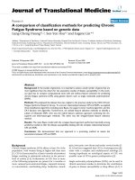
In this paper, we suggest a new application for graphene
in vacuum nanoelectronics. Figure 1 shows a conceptual
schematic of a graphene-based triode device. Such a
graphene triode structure can be used as a fundamental unit
for vacuum nanoelectronics. The triode has an in-plane
graphene tip (emitter) with the other in-plane electrodes
used as source, drain, and gate on the substrate. Depending
on the gate voltage applied, electrons are emitted from the
graphene tip creating an electron current that can be
modulated on and off. To realize this conceptual device,
the field emission characteristics of graphene layers with
different thicknesses need to be characterized.
To create the graphene layer for this experimental study,
graphene sheets were prepared by mechanical exfoliation
and placed on insulating SiO
2
substrate. Figure 2 shows the
mechanical exfoliation process of graphene sheets on SiO
2
.
A thermo-curable elastomer, polydimethylsiloxane (PDMS,
S. W. Lee Á S. S. Lee
Department of Mechanical Engineering, KAIST, Daejeon, Korea
E H. Yang (&)
Department of Mechanical Engineering, Stevens Institute
of Science and Technology, Hoboken, NJ, USA
e-mail:
123
Nanoscale Res Lett (2009) 4:1218–1221
DOI 10.1007/s11671-009-9384-9
Sylgard 184, Dow Corning Co.) film was prepared using a
standard recipe on an oxidized Si wafer (see Fig. 2a). The
curing temperature and time were 65 °C and 4 h, respec-
tively. After peeling the film from the wafer, its polished
side was scrubbed on a highly oriented pyrolyzed graphite
(HOPG) block (see Fig. 2b, c), and lifted off, transferring
graphene layers to the PDMS (Fig. 2d). The exfoliated
graphene layers were transferred onto SiO
2
thin film by
scrubbing the PDMS film and subsequently detaching,
leaving behind thin graphene layers (see Fig. 2e, f). In order
to find and evaluate the graphene layers, the thickness of
SiO
2
layer on Si was set to 300 nm considering optical
interference [8].
A Zyvex Nanomanipulator operating inside a scanning
electron microscope (SEM: XL-40 SEM, FEI Co.) was
used to measure field emission from individual graphene
sheets (Fig. 2). Figure 3 shows the schematic view of the
experimental setup for measuring a field emission current
from graphene sheets. In the SEM vacuum chamber, two
tungsten tips were located on the graphene sample; one was
contacted directly to the sample and grounded as a cathode,
and the other was placed an arbitrary distance, d, apart
from the edge of the sample as the anode. The tungsten tips
were connected to a Keithley semiconductor measurement
system via a feed-through in the vacuum chamber to apply
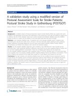
and sense the electric signal for field emission. Figure 4a
shows an optical image of the graphene sheets on SiO
2
layer. The thickness of the layer was optically measured on
300 nm thick SiO
2
layer by using the change of color due
to optical interference and transparency [8]. The color
change as the number of graphene layers varies is clearly
distinguishable. In Fig. 4a, Cobalt blue, purple, and light
Fig. 1 Conceptual schematic
view of a graphene-based triode
as a fundamental unit for
vacuum nanoelectronics.
Depending on the gate voltage
applied, electrons are emitted
from the graphene tip creating
an electron current that can be
modulated on and off
Fig. 2 Fabrication process of
graphene sheets using a
mechanical exfoliation method.
The graphene sheets are
transferred from HOPG block to
SiO
2
layer
Nanoscale Res Lett (2009) 4:1218–1221 1219
123
purple stand for 8, 4 and 2 nm thicknesses, respectively.
Figure 4b shows an SEM image of graphene sheets with a
pair of tungsten tips controlled by the nanomanipulator.
After adjusting the position of the tips, a positive
potential was applied to the second tip. The current was
then measured during a voltage sweep. Figure 5a shows
I–E curves of graphene for an arbitrary gap \1 lm. The
graphene sheet started to emit electron current around 20 V
and increased exponentially up to 170 nA following the
behavior of the Fowler–Nordheim relationship. The field
emission current fluctuated for applied voltages higher than
33 V. Figure 5b shows F–N curves obtained as a result of
field emission from a graphene sheet. As shown in Fig. 5a,
the emission current is increased exponentially, and the
F–N curve shows linear relationship following the field
emission behavior. The estimated turn-on voltages of the
tested graphene sheet is 12.1 V, where the slope of F–N
curve is changed and the linear region (red line) begins as
shown in Fig. 5b. In order to estimate the field-enhance-
ment factor, b, F–N parameters were evaluated by linear fit
of the red line as shown in the equations [9, 10].
Ið EÞ¼A
q
8p
2
"hu
1
u
ðbEÞ
2
exp À
4
3"hðbEÞ
ffiffiffiffiffiffiffiffiffiffiffi
2mu
3
p
ð1Þ
ln
I
E
2
!
¼À
b
b
u
3
2
1
E
!
þ ln aAb
2
¼À21:7
1
E
!
À 93:5 ð2Þ
b ¼ 6:83 Â10
3
V
À
1
2
lm
À1
ð3Þ
where I: current, E: electric field (V/d), b: field-enhance-
ment factor, u: work function, A: area, "h: reduced Planck
constant, and m: electron mass. Assuming the work func-
tion of graphene is 5 eV and the gap between the graphene
sheet and the nanomanipulator tip is 1 lm, the estimated
field-enhancement factor, b, is 3519. It is found that the
measured field-enhancement factor is comparable with
previous results of graphene film prepared by electropho-
resis [7], and the field emission efficiency of graphene is
twice as high as other carbon nanomaterials such as CNT
and diamond film [10, 11].
From the experimental results, it is found that one can
further reduce the voltage for electron emission as the
fabrication process is refined to create a fine emitter tip
from graphene sheets. The field emission properties of
graphene need further investigation in terms of the number
of graphene layers and crystallographic arrangement of the
carbon lattice. In the near future, a planar triode device will
be studied for next generation vacuum nanoelectronics.
This field-emitting nanodevice based on the planar form
of graphene potentially allows for top-down CMOS com-
patible process flows, an advantage for potential industrial
fabrication of electronic devices. For applications where
high field emission currents or low turn-on voltages are
Fig. 4 Graphene sample a optical image of graphene sheets on SiO
2
. The color of graphene sheets determines thickness of the graphene layer.
Scale bar:6lm. b SEM image of a graphene sample with tungsten tips controlled by nanomanipulator
Fig. 3 Schematic view of the experimental setup using a
nanomanipulator
1220 Nanoscale Res Lett (2009) 4:1218–1221
123
required, nanodevices based on graphene would inherently
provide the necessary alignment based on its crystallo-
graphic nature.
Acknowledgments This work has partially been supported by
Exchange Student Program by Brain Korea 21, Award No KUK-F1-
038-02 made by King Abdullah University of Science and Technol-
ogy (KAUST) and National Science Foundation (Major Research
Instrumentation Program, Award No. DMI-0619762).
References
1. W.A. de Heer, A. Chatelain, D. Uarte, Science 270, 1179 (1995)
2. H.M. Manohara, M.J. Bronikowski, M. Hoenk, B.D. Hunt, P.H.
Siegel, J. Vac. Sci. Technol. B 23, 157 (2005)
3. A.K. Geim, K.S. Novoselov, Nat. Mater. 6, 183 (2007)
4. K.S. Novoselov, A.K. Geim, S.V. Morozov, D. Jiang, Y. Zhang,
S.V. Dubonos, I.V. Grigorieva, A.A. Firsov, Science 306, 666
(2004)
5. N. Tombros, C. Jozsa, M. Popinciuc, H.T. Jonkman, B.J. van
Wees, Nature 448, 571 (2007)
6. J.J. Wang, M.Y. Zhu, R.A. Outlaw, X. Zhao, D.M. Manos, B.C.
Holloway, V.P. Mammana, Appl. Phys. Lett. 85, 1265 (2004)
7. Z.S. Wu, S. Pei, W. Ren, D. Tang, L. Gao, B. Liu, F. Li, C. Liu,
H M. Cheng, Adv. Mater. 21, 1756 (2009)
8. P. Blakea, E.W. Hill, H. Castro Neto, K.S. Novoselov, D. Jiang,
R. Yang, T.J. Booth, A.K. Geim, Appl. Phys. Lett. 91, 063124
(2007)
9. R.H. Fowler, L. Nordheim, Proc. R. Soc. (London) A119, 173
(1928)
10. X. Lu, Q. Yang, C. Xiao, A. Hirose, T. Tiedje, J. Phys. D Appl.
Phys. 40, 4010 (2007)
11. J.M. Bonard, R. Gaal, S. Garaj, L. Thien-Nga, L. Forro, K. Ta-
kahashi, F. Kokai, M. Yudasaka, S. Iijima, J. Appl. Phys. 91,
10107 (2002)
Fig. 5 a I–E plot for emission current. b F–N plot for emission
current
Nanoscale Res Lett (2009) 4:1218–1221 1221
123