Báo cáo hóa học: " Rapid Concentration of Nanoparticles with DC Dielectrophoresis in Focused Electric Fields" pot
Bạn đang xem bản rút gọn của tài liệu. Xem và tải ngay bản đầy đủ của tài liệu tại đây (932.39 KB, 6 trang )
NANO EXPRESS
Rapid Concentration of Nanoparticles with DC Dielectrophoresis
in Focused Electric Fields
Dafeng Chen
•
Hejun Du
•
Chee Yong Tay
Received: 24 August 2009 / Accepted: 18 September 2009 / Published online: 1 October 2009
Ó to the authors 2009
Abstract We report a microfluidic device for rapid and
efficient concentration of micro/nanoparticles with direct
current dielectrophoresis (DC DEP). The concentrator is
composed of a series of microchannels constructed with
PDMS-insulating microstructures for efficiently focusing
the electric field in the flow direction to provide high field
strength and gradient. The location of the trapped and
concentrated particles depends on the strength of the
electric field applied. Both ‘streaming DEP’ and ‘trapping
DEP’ simultaneously take place within the concentrator at
different regions. The former occurs upstream and is
responsible for continuous transport of the particles,
whereas the latter occurs downstream and rapidly traps the
particles delivered from upstream. The performance of the
device is demonstrated by successfully concentrating
fluorescent nanoparticles. The described microfluidic con-
centrator can be implemented in applications where rapid
concentration of targets is needed such as concentrating
cells for sample preparation and concentrating molecular
biomarkers for detection.
Keywords Microfluidics Á DC dielectrophoresis Á
Nanoparticles Á Electrokinetics
Introduction
The ability to concentrate or extract micro/nanoparticles,
such as cells, viruses, bacteria, and DNA, from the
background matrix is essential to many biomedical appli-
cations. The form of these particles in high concentration
facilitates the subsequent analytical and processing steps.
For example, current methods in microbial analysis of water
quality require subpopulations (e.g. E. coli) sampled in
detectable levels of concentration [1]. In the process of gene
hybridization, rates can be accelerated by concentration of
single-stranded DNA. The sensitivity of fluorescence-based
bioassays is greatly improved with pre-concentrated labeled
targets. In recent years, more and more biological and
chemical assays are conducted in microscale devices with
the rapid development of micrototal analysis systems
(l-TAS) [2]. Traditional methods of concentrating samples
by centrifuging and subsequently removing the supernatant
are not amenable to the format of microchips. A number of
methods have been reported concerning on-chip microflu-
idic concentration and manipulation of micro/nanoparticles
such as dielectrophoresis [3–5], optical tweezers [6], and
ultrasonic wave [7]. They are readily integrated into mic-
rodevices by patterning micro/nanometal electrodes (in the
case of dielectrophoresis) or using remote manipulation
with laser or ultrasound.
We report here a direct current dielectrophoresis-based
method for rapid concentration of nanoparticles in a
microfluidic device. Dielectrophoresis (DEP) is the motion
of a particle in a non-uniform electric field due to the
unbalanced electrostatic forces on the particle’s induced
dipole [8]. This phenomenon has been widely used for
concentration, manipulation, separation, sorting, and
transport of particles such as beads, bacteria, and cells [3–5,
9–12]. The majority of these applications employ AC
electric fields generated by closely spaced microelectrode
arrays that are generally constructed with MEMS-based
microfabrication techniques. AC fields promote lower
electrode polarization and electrophoretic effects. However,
D. Chen (&) Á H. Du Á C. Y. Tay
School of Mechanical & Aerospace Engineering,
Nanyang Technological University, 50 Nanyang Avenue,
Singapore 639798, Singapore
e-mail:
123
Nanoscale Res Lett (2010) 5:55–60
DOI 10.1007/s11671-009-9442-3
AC DEP faces certain issues that limit its applications, such
as electrode fouling and electric field decay above the
microelectrodes. An alternative to AC dielectrophoresis is
the insulator-based DEP (iDEP) or DC DEP [5, 13, 14], in
which no metal microelectrodes are embedded in the chip
and DC electric fields are applied from an external electrode
pair. This simplifies the fabrication of microdevices by
eliminating the metal deposition processes. Insulator
structures are robust and chemically inert. Effects such as
electrochemical reactions and electrolysis observed in AC
DEP are less likely to occur in iDEP. Cummings and Singh
observed two flow regimes in insulator-based DEP: (1)
‘streaming DEP’ where streams of highly concentrated and
rarified particles were created between the insulating posts
at relatively low voltages and (2) ‘trapping DEP’ where
particles were trapped around the insulating posts at higher
voltages [15]. These observations lead to potential appli-
cations, for example, streaming DEP can be used to focus
and transport particles, and trapping DEP can be used for
particle concentration and filtration. The mechanics behind
the phenomenon is the competition between electrokinetic
(electrophoresis and electroosmosis) and dielectrophoretic
forces [15]. The former is linearly proportional to the
electric field, while the latter is proportional to the field
squared. At low voltages, electrokinetic flow is dominant
over DEP and diffusion, resulting in the regime of stream-
ing DEP. At higher voltages, DEP is dominant, resulting in
trapping DEP. This letter describes an insulating micro-
structure that is designed to highly focus and thus ‘amplify’
the electric field. Upon the application of voltage, the
generated electric field is focused in the direction of fluid
flow. Trapping DEP first occurs at these field-focused areas
located at the downstream, while streaming DEP occurs
upstream and continuously transports and delivers the par-
ticles. The described setup is capable of rapidly concen-
trating and collecting nanoparticles from continuous flow
that is driven by electroosmosis.
Materials and Methods
The Microstructure for Field Focusing
In the case of DC DEP, the non-uniformity of electric field is
generally created by embedded obstacles such as a specifi-
cally arranged array of insulators. Delicately designed
insulators lead to useful distribution of the electric field as
well as the resulting electrostatic forces that are associated
with the field, such as DEP, electrophoretic, and electro-
osmotic forces. The proposed microdevice is composed of a
delicate insulating structure constructed in a channel for the
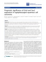
purpose of field focusing (Fig. 1). A simple and effective
field-focusing insulator structure is shown in Fig. 1a, which
is formed by an array of circular posts spaced by different
distances (d1 \ d2). An electric field is generally applied
externally from the two electrodes (anode and cathode,
respectively) located at opposite ends of the channel. Upon
the application of the field, a non-uniform distribution is
generated along the insulators, as indicated by the field lines.
Depending on the patterns of the insulators, the field is rel-
atively concentrated in certain areas. ‘Field-focused’ areas
are of higher non-uniformity compared to the ‘‘unfocused’’
areas and therefore are more preferable for trapping DEP.
Derived from the design in Fig. 1a, a more effective insu-
lating structure is shown in Fig. 1b, which is referred to as a
‘tree system’ for field focusing. The tree system enables
multilevel-focusing operations in the direction of flow (from
the left to the right) at consecutive regions (as indicated with
numbers 1–4). From the entry on the left to the exit on the
right, the electric field gradually converges. This results in
interesting movement of particles carried by the fluid flow
due to the combined effects of various forces.
Theoretical
Suspended particles in the electric field experience a number
of significant forces including DEP, electrophoretic, and
d1
d2
d1<d2
Insulating post
Flow
E
Focused
Field
20 um
height
Main
Channel
Flow
Insulators
1st focused field
2nd focused
field
Outlet
Inlet
(a)
(b)
Fig. 1 a Diagram of a simple design for field focusing via insulator
posts. The electric field (E) is indicated with field lines. b An
insulating ‘tree’ structure for rapid electric field focusing
56 Nanoscale Res Lett (2010) 5:55–60
123
electro-osmotic effects. The superposition of electrophoretic
and electroosmotic transport is generally termed electroki-
netic flow. The resulting motion of the particle is determined
by the superposed electrokinetic velocity [15]
u
ek
¼ l
ek
E ¼ u
eo
þ u
ep
¼ðl
eo
À l
ep
ÞE ð1Þ
where l
ek
, l
eo
, and l
ep
are the electrokinetic, electroos-
motic, and electrophoretic mobility, respectively. E is the
electric field. Equation 1 indicates that the electrokinetic
motion of the particles is linearly proportional to the local
electric field. Under ideal electrokinetic flow, particles flow
along the electric field lines, and no concentration of par-
ticles occurs.
On the other hand, dielectrophoretic velocity, u
dep
, which
is induced by the dielectrophoretic force in a non-uniform
field, is proportional to the gradient of the electric field [8]
u
dep
¼ l
dep
rðE Á EÞð2Þ
where l
dep
is the dielectrophoretic mobility.
In contrast to electrokinetic flow, dielectrophoretic
motion is along the electric field gradient, and the transport
can result in concentration, focusing, or trapping of parti-
cles in non-uniform fields. Such field gradients are readily
produced either by embedded metal electrodes in the case
of AC dielectrophoresis or by insulating posts within the
channel exposed to an external electric field. Dependent on
the polarizability of the particles and suspended medium,
positive DEP (drawing particles to field maximum) or
negative DEP (repelling particles from field maximum)
takes place [8].
The above equations imply that the resulting particle
movement depends on the relative strengths of electroki-
netic and dielectrophoretic effects. As discussed in Ref.
[15], above a threshold electric field, DEP becomes dom-
inant over electrokinetic and diffusion effects. Particles
will be trapped and concentrated dielectrophoretically, and
this regime is called ‘trapping DEP’. In this work, we
proposed a field-focusing structure (Fig. 1b) in which rapid
electric field gradients are generated to readily induce
‘trapping DEP’. Electrokinetic flow is responsible for
particle transport, while dielectrophoresis is responsible for
local particle trapping.
Microfabrication and Experimental Setup
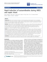
The microfluidic device containing the insulating microelec-
trodes was fabricated using conventional microfabrication
techniques (Fig. 2). The PDMS (polydimethylsiloxane)-
insulating microstructures were manufactured by casting
from a microfabricated silicon master. To fabricate the mas-
ter, a 10 lm thick layer of photoresist (AZ9260, Clariant,
Somerville, NJ) was spun and patterned on a 4-inch wafer
with a photolithography process (Fig. 2a). The patterned
photoresist served as the mask for the subsequent process of
deep reactive ion etching (DRIE). To form the complemen-
tary patterns in the master, an ICP (inductively coupled
plasma) deep RIE process was applied (Surface Technology
Systems plc, Newport, UK). The etching rate was about
3 lm/min with a gas recipe of 115-sccm SF
6
? 13-sccm 150
O
2
? 100-sccm C
4
F
8
at a cycling of 8 s passivation and 13 s
etching. Patterns of depth of 20–50 lm were fabricated
(Fig. 2b, c). The master surface was then passivated with gas
C
4
F
8
for 5 min. The passivation reduced the adhesion of
PDMS to the master surface and in turn facilitated the sub-
sequent PDMS peeling-off step. PDMS mixture was then
poured onto the master and incubated at room temperature
overnight (Fig. 2d). The cured PDMS film was peeled off
from the master, and the insulating microstructures were
formed on the PDMS film (Fig. 2e). To construct an enclosed
microfluidic device containing the microstructures and
microchannels, the PDMS film was then bonded to a glass
slide (Fig. 2f).
Figure 3a depicts a photograph of the PDMS-insulating
microstructure fabricated with the process depicted in
Fig. 2. Microchannels formed by the PDMS guide the
EOF-driven flow from the left to the right. In the flow
direction, the microchannels merge into subsequent mi-
crochannels, terminating in a single outlet at the very right.
In the proposed structure, four trapping regions (indicated
as ‘Region1’–‘Region 4’) are formed. These regions have
photoresist
silicon
(a) Pattern a mask with photolithography
(b) Deep RIE etching
(c) Master formed by removing the resist
(d) Cast PDMS
(e) Peel off the PDMS film
(f) Bond the PDMS film to a glass slide
glass
PDMS
20um- 50um
PDMS
Fig. 2 Diagrams illustrating the
fabrication of the microfluidic
device containing PDMS-
insulating microstructures
Nanoscale Res Lett (2010) 5:55–60 57
123
been designed to effectively concentrate particles at vari-
ous conditions by focusing the electric field. Figure 3b
shows a top view of the completed microfluidic chip con-
taining the microfabricated insulators and the inlet/outlet
reservoirs. To generate the electric field, two Pt electrodes
were vertically placed in the outlet and inlet reservoirs,
respectively. In experiments, the solution containing the
particles was introduced at the inlet reservoir. The liquid
then automatically filled the channel due to the capillary
action. The motion of particles was imaged using an epi-
fluorescent microscope (Nikon TE2000-S).
Results and Discussions
To investigate how the electric field is focused within the
tree system, the field distribution was simulated with a
finite element software (Femlab 3.2, COMSOL Inc., Bur-
lington, MA, USA). In the simulation, the DC electric field
was defined to apply from both the ends of the main
channel. The simulated non-dimensional electric field (E)
distribution is shown in Fig. 4. The microstructure is
divided into four regions as indicated with ‘1’–’4’ in the
figure. From Regions 4–1, the field strength increases
gradually. The insulating concentrator was designed in this
way to focus the electric field in the direction of the fluid
flow (from the left to the right).
The performance of the microfluidic concentrator was
tested with green fluorescent polystyrene microspheres of
diameter of 930 nm (Duke Scientific Co., CA, USA). The
microspheres emit green light (508 nm) when they are
excited by blue light (468 nm). Before use, the particles
were re-suspended at low concentration in deionized water,
and the conductivity of the medium was adjusted by adding
phosphate buffer solution (PBS, Fisher Scientific, NJ). The
conductivity was measured using a conductivity meter with
graphite sensor electrodes (Dist3WP, Hanna Instruments
Inc., RI). Solutions of 1.0–10.0 mS/m were used in the
experiments. To begin, a suspension of fluorescent micro-
spheres was injected into the inlet reservoir of the micro-
fluidic chip with a pipette. To generate the electric field, a
DC voltage was applied to the platinum wire electrodes
placed in the two reservoirs at the ends of the channel. To
investigate the effect of electric field strength on the par-
ticle motion, the applied voltage on the two electrodes was
increased incrementally from 50 to 1,000 V with a high-
voltage power supply (PS350, Stanford Research). The
corresponding electric field was *20–400 V/cm.
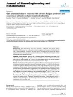
Figure 5 shows the observed particle behavior within
the microchannels of the insulating structure for increasing
electric fields. Dark areas are the solid insulators and bright
areas are the microchannels filled with flowing fluorescent
particles. At low electric field of 40 V/cm, streaming di-
electrophoresis was observed (Fig. 5a). Streamlines of
particles carried by the EOF were formed within the mi-
crochannels. Particles entered from the left of the channels,
traversed the whole structure, and then exited at the right
outlet. No obvious concentration of particles was observed
PDMS
microchannel
channel
Flow
Region1Region2Region3
Region4
100 ul
Outlet
Insulators
Reservior
Electrode
Channel
Flow
Electrode
1'x0.5'
Microscope
Cross-section
Top view
(a)
(b)
Fig. 3 a Photograph of the PDMS-insulating microstructure for
concentrating of particles. b Diagram showing the microfluidic chip
and experimental setup composed of microfabricated insulators, inlet/
outlet reservoirs, two electrodes, and a fluorescence microscope
0.2
0.4
0.6
0.8
1.0
1.2
1.4
1.6
1.8
Min 2.5e-3
Max 0.186
Region
12
3
4
Fig. 4 Simulated non-dimensional electric field (E) distribution in
the concentrator. The electric field is applied from the ends of the
main channel
58 Nanoscale Res Lett (2010) 5:55–60
123
in this regime (streaming DEP). In the low electric field
regime, drag forces on the particles from electrokinetic
flow dominated the attractive effects of positive DEP and
thus resulted in the streaming movement along the micro-
channels. As the electric field increased to 120 V/cm,
trapping of particles began to occur at the right (Region 1)
of the concentrator (Fig. 5b). Due to the focused electric
field in this region, the DEP force began high enough to
overcome the electrokinetic effects, resulting in the trap-
ping of particles in this region. Because of the trapping,
fewer particles exited the outlet. On the other hand,
streaming DEP still occurred in the other regions (the left
part of the concentrator). The co-existence of both
streaming DEP and trapping DEP highly improved the
concentration efficiency: the streaming DEP was respon-
sible for continuously transporting of the particles from the
left to the right, while trapping DEP was responsible for
trapping the delivered particles. As the applied field further
increased to 160 V/cm, the loss of particles at the outlet
disappeared, meaning that the concentrator trapped all the
incoming particles delivered by the flow (Fig. 5c). In
addition, the particles were highly condensed as indicated
by the intensity of the fluorescence. Similarly, trapping
DEP began to occur in ‘Region 2’ as the applied field
increased to 200 V/cm (Fig. 5d) and occurred in ‘Region
3’ and ‘Region 4’, respectively, as the applied field
increased to 240 V/cm or higher (Fig. 5e). At this point,
the concentrator trapped all the particles entered from the
inlet and packed them into a dense format within the mi-
crochannels. To collect the concentrated particles, the
residual solution in the reservoirs was first discarded. The
applied voltage was then turned off, and a pressure source
(generated with a syringe) was applied from the inlet to
propel the particles to the outlet reservoir. The solution
collected from the concentrator was observed to contain
particles in a high concentration. We also carried out
experiments with particles of diameter of 500 nm (not
shown). The observations were similar but required higher
electric field for the same effect.
Summary
We have demonstrated a microfluidic concentrator for
rapid and efficient trapping of nanoparticles. The concen-
trator is composed of a series of microchannels formed by
Fig. 5 Concentration of green
fluorescent submicron
polystyrene particles in the
insulating microstructures.
a–e Depicts the concentration at
different regions as the applied
voltage increased. Dark areas
are the PDMS structures, and
bright (green) areas are the
microchannels formed by the
PDMS. The flow direction is
from the left to the right
Nanoscale Res Lett (2010) 5:55–60 59
123
PDMS-insulating microstructures. The applied fields were
focused stepwise within the microchannels. Streaming
DEP occurred at low electric fields, and trapping DEP
occurred at higher electric fields. As the electric field
increased, concentration of nanoparticles began to occur at
different regions. Both streaming DEP and trapping DEP
could simultaneously occur. The concentration was very
rapid and efficient as the streaming DEP delivered particles
and trapping DEP trapped the delivered particles. The
proposed concentrator design can be re-configured into a
format with more or less trapping regions, depending on
the applications. Furthermore, the microfluidic concentra-
tor can be implemented in applications where concentra-
tion of targets are needed, such as the concentration of cells
for sample preparation and the concentration of molecular
biomarkers for biological assays.
References
1. A.E. Greenberg, L.S. Clesceri, A.D. Eaton (eds.), Standard
Methods for the Examination of Water and Wastewater, 21st edn.
(American Public Health Association, American Water Works
Association and water Environment Federation, USA, 2005)
2. D.R. Reyes et al., Micro total analysis systems. 1. Introduction,
theory, and technology. Anal. Chem. 74, 2623–2636 (2002)
3. M. Durr et al., Microdevices for manipulation and accumulation
of micro- and nanoparticles by dielectrophoresis. Eletrophoresis
24, 722–731 (2003)
4. D.F. Chen, H. Du, W.H. Li, A 3D paired microelectrode array for
accumulation and separation of microparticles. J. Micromech.
Microeng. 16, 1162–1169 (2006)
5. B.H. Lapizco-Encinas et al., Insulator-based dielectrophoresis for
the selective concentration and separation of live bacteria in
water. Electrophoresis 25, 1695–1704 (2004)
6. M.P. Sheetz, Laser Tweezers in Cell Biology (New York, Aca-
demic Press, 1998)
7. A. Nilsson et al., Acoustic control of suspended particles in micro
fluidic chips. Lab Chip 4, 131 (2004)
8. T.B. Jones, Electromechanics of Particles (Cambridge University
Press, Cambridge, 1995)
9. D.F. Chen, H. Du, A dielectrophoretic barrier-based microsystem
for separation of microparticles. Microfluid. Nanofluid. 3, 603–
610 (2007)
10. J.G. Kralj et al., Continuous dielectrophoretic size-based particle
sorting. Anal. Chem. 78, 5019–5025 (2006)
11. R. Pethig, Dielectrophoresis: using inhomogeneous AC electrical
fields to separate and manipulate cells. Crit. Rev. Biotechnol. 16,
331–348 (1996)
12. H.B. Li, R. Bashir, Dielectrophoretic separation and manipulation
of live and heat-treated cells of Listeria on microfabricated
devices with interdigitated electrodes. Sens. Actuators B 86, 215–
221 (2002)
13. Yuejun. Kang et al., DC-Dielectrophoretic separation of biolog-
ical cells by size. Biomed. Microdev. 10, 243–249 (2007)
14. C F. Chou et al., Electrodeless dielectrophoresis of single- and
double-stranded DNA. Biophys. J. 83, 2170–2179 (2002)
15. E.B. Cummings, A.K. Singh, Dielectrophoresis in microchips
containing arrays of insulating posts: theoretical and experi-
mental results. Anal. Chem. 75, 4724–4731 (2003)
60 Nanoscale Res Lett (2010) 5:55–60
123