Báo cáo hóa học: " Effect of Substrate Morphology on Growth and Field Emission Properties of Carbon Nanotube Films" pptx
Bạn đang xem bản rút gọn của tài liệu. Xem và tải ngay bản đầy đủ của tài liệu tại đây (668.03 KB, 8 trang )
NANO EXPRESS
Effect of Substrate Morphology on Growth and Field Emission
Properties of Carbon Nanotube Films
Sanjay K. Srivastava Æ V. D. Vankar Æ
Vikram Kumar Æ V. N. Singh
Received: 13 March 2008 / Accepted: 3 June 2008 / Published online: 13 June 2008
Ó to the authors 2008
Abstract Carbon nanotube (CNT) films were grown by
microwave plasma-enhanced chemical vapor deposition
process on four types of Si substrates: (i) mirror polished,
(ii) catalyst patterned, (iii) mechanically polished having
pits of varying size and shape, and (iv) electrochemically
etched. Iron thin film was used as catalytic material and
acetylene and ammonia as the precursors. Morphological
and structural characteristics of the films were investigated
by scanning and transmission electron microscopes,
respectively. CNT films of different morphology such as
vertically aligned, randomly oriented flowers, or honey-
comb like, depending on the morphology of the Si sub-
strates, were obtained. CNTs had sharp tip and bamboo-like
internal structure irrespective of growth morphology of the
films. Comparative field emission measurements showed
that patterned CNT films and that with randomly oriented
morphology had superior emission characteristics with
threshold field as low as *2.0 V/lm. The defective (bam-
boo-structure) structures of CNTs have been suggested for
the enhanced emission performance of randomly oriented
nanotube samples.
Keywords Carbon nanotubes (CNTs) Á Bamboo-
structured CNTs (BS-CNTs) Á Chemical vapor
deposition (CVD) Á Transmission electron microscopy
(TEM) Á Field emission
Introduction
Carbon nanotubes (CNTs) [1] have attracted wide attention
both in the research and industrial communities because of
their unique structural and physical properties. In particu-
lar, field electron emission from CNTs has been proposed
to be one of the most promising as far as its practical
application is concerned. This is because CNTs present
many advantages over conventional Spindt (Mo, Si, etc.)
emitters [2] such as (i) high chemical stability (resistance to
oxidation or other chemical species) and high mechanical
strength (Young’s modulus *1 TPa), (ii) high melting
point (*3550 °C) and reasonable conductivity (resistivity
*10
-7
Xm), (iii) high aspect ratio ([1000) with very
small tip radius to greatly enhance the local electric field,
and (iv) easy and low cost production, longer life time and
capability of producing high-current densities at low
operating voltages [3].
The potential of CNTs for field emission (FE) was first
reported in 1995. FE from an isolated single multiwalled
CNT (MWNT) was first observed by Rinzler et al. [4] and
that from a MWNT film was reported by de Heer et al. [5].
Since then a number of experimental studies on FE of
MWNTs synthesized by different processes, including arc
discharge and various versions of chemical vapor deposi-
tion (CVD) both with and without plasma, have been
investigated [6–17]. Several parameters such as density,
length of CNTs, open/closed tips, defects, adsorbates,
presence of metal particles, etc., have been reported to
affect the FE characteristics of MWNT films deposited
catalytically by different CVD techniques [18]. However, a
comparative measurement on FE properties of MWNT
films of different morphology grown by a single CVD
process is rarely reported. The FE properties of single-
walled CNTs (SWNTs) have also been investigated
S. K. Srivastava Á V. D. Vankar Á V. N. Singh
Department of Physics, Thin Film Laboratory, Indian Institute
of Technology Delhi, Hauz Khas, New Delhi 110016, India
Present Address:
S. K. Srivastava (&) Á V. Kumar
National Physical Laboratory, Dr. K.S. Krishnan Marg,
Pusa, New Delhi 110012, India
e-mail:
123
Nanoscale Res Lett (2008) 3:205–212
DOI 10.1007/s11671-008-9138-0
[19, 20]. Synthesis of SWNTs is, however, a high-temper-
ature process and sometimes requires additional post-
synthesis processing for FE measurements. On the other
hand, controlled and low-temperature growth of CNT films
is desirable for FE-based applications. CNTs grown at low
temperature by any CVD process, with or without plasma,
in general, have many structural defects. For example,
CNTs prepared by plasma-enhanced CVD process using
combination of hydrocarbon and NH
3
or N
2
have generally
bamboo-structure popularly known as bamboo-shaped
CNTs (BS-CNTs) [21–23] rather than pure conventional
MWNTs. Therefore, structural characteristics of the MWNTs
and overall morphology of the films are critical for FE. This
is also important because both structure and morphology of
CNT films strongly depend on growth techniques and
related parameters such as temperature, catalyst, feed gases,
etc. Substrate morphology may also have significant impact
on the growth of CNT films, particularly in high-frequency
plasma CVD process. Microwave plasma-enhanced CVD
(MPECVD) is such a process and has been successfully
used to deposit a variety of nanostructured carbon films
ranging from diamond [24], carbon nanosheets [25] CNTs
[20, 23], and carbon nanobells [26, 27] to monochiral
MWNTs [28] on Si substrates. This technique offers the
advantage of growing these materials at relatively lower
substrate temperatures and at a faster rate. Microwave
plasma operating at low pressure is a low-temperature
plasma due to the non-equilibrium state between the elec-
trons and other heavy particles in the plasma space and full
of active species. The plasma not only ionizes the gas but
also causes local surface heating [29]. Consequently,
growth temperature could be significantly decreased com-
pared to non-plasma CVD process. Hence the motivation of
the present study was to investigate the effect of substrate
morphology on the growth of CNT films by an MPECVD
process and investigate their comparative FE properties and
structure–morphology dependence.
In this article, CNT films with unique morphological
features were deposited on substrates with different surface
morphology by the MPECVD process and their FE char-
acteristics were investigated. The correlation between
structure, morphology, and FE properties of CNTs has been
discussed.
Experimental
CNT films were deposited by tubular MPECVD process.
The detail of the experimental set-up is described else-
where [25]. In brief, tubular MPECVD system is equipped
with a 1.2 kW 2.45 GHz microwave source and a traverse
rectangular waveguide to couple the microwave to a
tubular quartz tube for generating the plasma. Substrate
was placed on a quartz holder that was fully electrically
insulated and the substrate was immersed in the plasma
zone. It is important to mention that no additional heater
was used for substrate heating and no biasing was applied
to the substrate. Four set of samples were deposited on p-Si
(100) substrates with different initial surface morphology: (i)
mirror-polished Si substrates (sample 1), (ii) mirror polished
but Fe patterned (sample 2), (iii) mechanically polished
having randomly distributed pits of different shape and size
(sample 3), and (iv) electrochemically etched Si having
uniformly distributed pores (sample 4). The mechanical
polishing of Si wafer was carried out using diamond paste
containing diamond particles of size *1 lm for 1 h. Porous
Si substrates were prepared by the electrochemical anod-
ization of the Si-wafer. The electrochemical bath consisted
of 48% hydrofluoric acid + 99% dimethyl formamide in the
ratio of 1:5. A graphite sheet and Si wafer were used as
cathode and anode, respectively. Aluminum (Al) thin films
were deposited on the Si substrates by thermal evaporation
of Al wires (LEICO Industries, New York, USA; diameter:
0.5 mm and purity 99.99%), followed by vacuum annealing
at 350 °C for making proper electrical contacts. Distance
between the cathode and anode was kept as 2 cm and the
current density was maintained at *10 mA/cm
2
. The etch-
ing was carried out for 10 min. Thin films of Fe of thickness
*10 nm were deposited on such Si substrates by thermal
evaporation of Fe ingots (CERAC Inc., USA, purity 99.95%)
at a base pressure of 2.0 9 10
-6
Torr. Fe patterns (20 9 20
lm) were made by standard photolithography lift-off tech-
nique. The Fe-coated substrates were then loaded into the
MPECVD reactor for growth process. The detail of the
growth process is described in our previous article [30]. The
Fe-coated substrates were pretreated in NH
3
plasma for 10
min at an input microwave power of 500 W, operating
pressure of 5 Torr, and NH
3
flow rate of 40 sccm. For growth,
C
2
H
2
was introduced at a flow rate of 20 sccm keeping other
parameters constant. Under these conditions, substrate
temperature was estimated to be *600 °C. All the films were
deposited for 10 min. After growth, plasma was switched off
and samples were cooled down to room temperature under
flowing NH
3
gas.
Scanning electron microscope (SEM) (LEO 435 VP)
operating at 15 kV was used for surface morphological
features of the substrate and films. Structural analysis of
CNTs was carried out by transmission electron microscope
(TEM) (Philips, CM 12) operating at 100 kV as well as
FEI, Technai G20-stwin, 200 kV equipped with energy
dispersive X-ray spectroscopy (EDAX) (EDAX company,
USA). TEM specimen preparation is described in our
previous article [23]. Field emission measurements were
carried out by planar diode assembly at a base pressure
of *2.0 9 10
-6
Torr. Spacing between electrodes was
kept as *300 lm. The FE current was measured with
206 Nanoscale Res Lett (2008) 3:205–212
123
increasing voltage. Emission current density was calculated
by dividing the emission current with the exposed area of
the sample. Emission performances of all of the four
samples were analyzed using Fowler–Nordheim (F-N)
model [31]. For recording FE patterns, tin oxide (TO)
coated glass was set as anode and Cu-doped cadmium
sulfide (CdS) films deposited by spray pyrolysis was used
as anode.
Results and Discussion
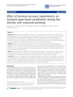
SEM micrographs of mechanically polished and the elec-
trochemically etched Si wafers are shown in Fig. 1a, b,
respectively. Randomly oriented pits of different shapes
and size are observed after mechanical polishing. Electro-
chemical etching of Si wafers produced uniformly
distributed pores of size *1 lm. Figure 1c, d shows typ-
ical surface morphology of as-deposited and patterned Fe
films, respectively, on mirror-polished Si wafers. The film
appears to be smooth and continuous. However, continuous
film after NH
3
plasma treatment resulted into semi-spher-
ical nanoparticles of different size as shown in Fig. 1e.
Average size of the nanoparticles was estimated to be *65
nm. In case of mechanically polished or electrochemically
etched Si wafers, Fe nanoparticles were also found in the
pits/pores after plasma treatment of Fe film on such sub-
strates. These particles probably seeded the nucleation and
growth of CNTs.
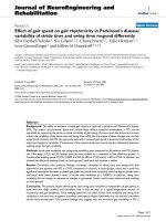
Surface morphology of CNT films deposited on such
substrates is presented in Fig. 2. Sample 1 consists of high
density ([10
9
cm
-2
) of vertically aligned CNTs (Fig. 2a).
Sample 2 also has vertically aligned CNTs but only in Fe-
patterned area (Fig. 2b). This confirms that the growth in
the present process is essentially catalytic. Some CNTs in
the edges of the pattern are not aligned vertically but are
lean toward free area. As a result, interconnection between
few CNT patterns is also observed by some of the edge
nanotubes. The morphology of CNT films on mechanically
polished substrates (sample 3) is very interesting as shown
in Fig. 2c. CNTs around the pits are aligned such as to
appear like flowers. Central part of the pits seems to be free
Fig. 1 SEM micrographs of (a)
mechanically polished Si, (b)
electrochemically etched
(porous) Si, (c) as-deposited Fe
film, (d) as-deposited patterned
Fe film, and (e)NH
3
plasma-
treated Fe film
Nanoscale Res Lett (2008) 3:205–212 207
123
of CNTs and nanotubes are aligned along the wall of the
pits. Similar features were observed around all the pits.
However, shape and size of the CNT flowers were
dependent on local geometry of the pit. Figure 2disan
SEM micrograph of typical CNT films on porous Si sub-
strates (sample 4) showing honeycomb-like morphology.
Similar to sample 3, in this case also nanotubes seem to
grow out from the pores along their sidewalls and finally
meet together with the CNTs of nearby pores. However, for
longer growth time, nanotubes merged together and the
pores were not clearly visible. Average CNT length was
estimated to be *20 lm in the first two samples but the
length was slightly less for samples 3 and 4. The reduced
length could be due to random growth orientation of CNTs.
CNTs obtained on porous/mechanically polished Si
substrates have random orientations, whereas plain sub-
strates, in general, lead to vertically aligned growth. This
indicates that orientation of nanotubes is largely dependent
on the local geometry of the substrate. This was further
confirmed by the orientation of CNTs near the edge of the
substrates. Most of the nanotubes were found to be oriented
outward from the substrate edge almost normal to the side
of the substrate as shown in Fig. 3. It is known that local
electrostatic field gets generated on the substrate surface
immersed in the plasma [32] and this may affect initial
orientation of the growing nanotubes. In addition, local
electric field intensity is enhanced at sharp edges in the
microwave plasma [33]. It is also suggested that surface
plasmon can be excited efficiently in a microwave plasma
process with tubular geometry if the substrate is placed
Fig. 2 SEM micrographs of
CNT films: (a) sample 1, (b)
sample 2, (c) sample 3, and (d)
sample 4
Fig. 3 (a) SEM micrograph of a typical CNT film near the edge of
the substrate showing CNTs growing outward almost parallel to the
substrate: (a) top view and (b) side view
208 Nanoscale Res Lett (2008) 3:205–212
123
normal to the lower electrode, i.e., substrate surface facing
the microwave source [33]. In our case also, surface plas-
mon might be generated around the locally existing pores/
pits as pit walls are fully or partially normal to the sub-
strate. Therefore, local orientation of field lines around the
pits/pores of different size and shapes may be different
both in magnitude and direction [34, 35], resulting in
flower-like or honeycomb-like morphology of CNTs on the
mechanically polished or porous substrates. It is important
to note that the effect of electrostatic field is decisive in the
initial stage of the growth. However, in the later stage,
alignment may be controlled by the crowding effect [10].
The morphology observed in samples 3 and 4 is repro-
ducible with slight variation since it is dependent on the
local geometry of the pits/pores. Therefore, if the shape and
size of the pits/pores are properly controlled, this process
can be used for the synthesis of CNTs with predefined
morphology.
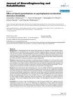
Irrespective of the growth morphology of the films, all
samples were found to have BS-CNTs. Figure 4a, b shows
typical TEM micrographs of BS-CNTs showing base and
tip sections, respectively. Each nanotube consists of many
short hollow conical compartments stacked in a way such as
paper cups. These nanotubes have sharp closed tips and
pear/cork-shaped catalytic particles attached at their bases.
Some of the BS-CNTs were open in the base region prob-
ably because of the detachment of the catalytic particle
during specimen preparation. The outer diameter of the
BS-CNTs was estimated in the range of 30–70 nm. How-
ever, some of the CNTs were of very large diameter (*150
nm). The tip diameters were in the range of 5–20 nm. The
magnified view of a tip section is shown in Fig. 3b. Some of
the large diameters BS-CNTs have very irregular and tilted
tips. This could be because of the process instability at the
nucleation stage of CNTs. These observations clearly sug-
gest that the growth of BS-CNTs in the present study was
governed by base mode. High-resolution TEM studies of
these CNTs showed many open edges on the outer surface,
particularly near the joints of the two compartments [23,
31]. This is accounted to the unique periodic structure
(periodic stacking of layers one above the other in such a
way to leave uniform outer diameter) of these BS-CNTs.
The BS-CNTs were found to be highly crystalline, which
has been discussed in detail in our previous articles [30, 31].
The structural characteristics are similar to the nanobells
structures called as polymerized carbon nitride nanobells
grown by the MPECVD process using methane (CH
4
) and
nitrogen (N
2
) precursors by Ma et al. [26] and Zhang et al.
[27]. However, the nanobells did not have regular conical
compartments and sharp tip. In addition, the compartments
in the nanobells were of much shorter length. The com-
partments in the present study have more regular conical
compartments (Fig. 4a, b).
EDAX analysis of BS-CNTs was also carried out during
TEM investigations (data not shown here) from both with
and without metal catalysts regions. The main elements
detected were C, O, Fe, Cu, and Si. Cu signal is attributed
to the copper micro-grid used for specimen preparation and
weak Si signal may be due to the substrate effect. No trace
of Al or any other impurities were observed on BS-CNTs
surface or in the catalyst particle. However, small amount
of nitrogen doping in the BS-CNT films (*1 at.%) was
observed by XPS measurements which get incorporated in
BS-CNTs during growth in C
2
H
2
–NH
3
plasma [31].
Nitrogen plays a critical role in the growth of compart-
mentalized CNTs or BS-CNTs in plasma CVD process
[23, 27]. NH
3
plasma consists of both atomic hydrogen and
Fig. 4 (a) Low magnification representative TEM micrograph of
bamboo-structured CNTs, (b) magnified view of tip end
Nanoscale Res Lett (2008) 3:205–212 209
123
nitrogen species compared to only nitrogen species in N
2
gas plasma. Also, it has low dissociation energy compared
to N
2
or H
2
and hence is a better dilution gas for the growth
of aligned and clean BS-CNTs at a faster rate. In situ
optical emission spectroscopy has shown that both hydro-
gen and nitrogen are essential for the growth of aligned
BS-CNTs by MPECVD process, and NH
3
is the main
source of atomic hydrogen in C
2
H
2
–NH
3
composition [23].
Presence of nitrogen in the plasma assures the formation of
bamboo-structure causing enhancement in bulk diffusion of
carbon in metal (Fe) catalyst. The bulk diffusion is mainly
responsible for the compartment formation and hence the
bamboo-structure [23]. In addition, nitrogen atoms get
incorporated in BS-CNTs, causing change in the electronic
structure [27, 30, 31]. Growth mechanism of BS-CNTs and
role of nitrogen in the formation of such structures have
been discussed in our previous article [23].
Figure 5 shows the comparative plot of integrated
emission current density (J) versus applied macroscopic
field (E) for four CNT samples. FE parameters such as
turn-on (E
to
) and threshold (E
th
) fields of these samples are
given in Table 1. The E
th
value observed for four samples
is in the range of 2.10–3.55 V/lm. This shows that
BS-CNT films have excellent field emission characteristics.
The excellent FE characteristics of BS-CNTs films could
be attributed to the following: (i) doping of CNTs with N
species which may increase the local density of states near
the Fermi level [36–38], (ii) BS-CNTs have lower work
function [39] compared to conventional CNTs, (iii) sharp
closed tips compared to the lower part of the tube which
enhances the aspect ratio, and (iv) metal (catalyst) particles
lying at the base of the nanotubes may play important role
in improving the emission property providing lower resis-
tance path at the substrate-film interface. The E
th
value in
the present study (2.10 V/lm) is higher than that reported
by Ma et al. [26] for polymerized carbon nitride nanobells
(1.0 V/lm) synthesized by MPECVD process using N
2
and
CH
4
precursors. These nanobells are highly defective.
Nitrogen doping reported in their case is *10 at.% which
is very high in comparison to BS-CNT films in the present
case (*1 at.%). High nitrogen doping and hence highly
defective structure may be the cause for high emission
current at low fields. Also, poor vacuum (*10
-6
Torr) in
the present case compared to Ref. [26](*10
-9
Torr) for
FE measurements could be another reason for higher E
th
values.
Among the four samples, sample 4 has shown the best
emission characteristics with the lowest E
th
of 2.10 V/lm
while vertically aligned CNT film has the highest E
th
value.
The patterned CNT film (sample 2) also has lower E
th
value compared to sample 1. The enhanced emission
characteristics of BS-CNT films with flower-like or honey-
comb morphology are attributed to the existence of many
open graphitic edges on the outer surface of the nanotubes
along the tube length, particularly near the joints of the two
compartments [23]. These open edges on the surface of
BS-CNTs act as additional emission sites [30, 31, 40]. On
the other hand, in case of vertically aligned BS-CNTs,
conventional MWNTs, or single walled CNTs, emission is
supposed to occur mainly from the tip section which may
further be limited by the screening of the electric field due
to neighboring tubes [41]. The screening effect is less
effective in case of patterned CNT films. In this case, CNTs
in the edge region may dominantly contribute more current
than dense interior region. It is to be noted that no signif-
icant emission current was observed with porous/
mechanically polished Si substrates. This confirmed that
emission occurred from CNTs only and not from the edges/
protrusions on the substrates. The geometrical enhance-
ment factors (b
H
) estimated from slopes of the F–N plots in
the high field region were found to be quite high. These are
6,252, 12,400, 12,114, and 9,450 for samples 1, 2, 3, and 4,
respectively. Such a high geometrical enhancement factor
has been reported in case of open-end CNTs [11].
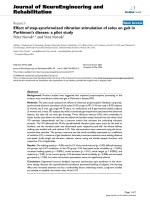
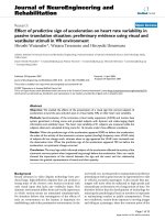
The sequence of emission patterns of typical BS-CNT
films of size *12 9 18 mm
2
grown on porous Si substrates
is shown in Fig. 6. The emission patterns were recorded
with increasing anode voltage. Initially very few emission
sites were found to be active. But the number increased
with increase in the applied field and emission from all
1.0 1.5 2.0 2.5 3.0 3.5 4.0 4.5
0
1000
2000
3000
4000
5000
6000
Sample 1
Sample 2
Sample 3
Sample 4
J(
µ
A/cm
2
)
E(V/µm)
Fig. 5 Comparative emission current density (J) versus macroscopic
field (E) plots for CNT samples of different morphology
Table 1 Comparative FE parameters (E
to
, E
th
, and b
H
) of CNT films
grown on different substrate morphology
Sample E
to
(V/mm) E
th
(V/mm) Enhancement factor (b
H
)
Sample 1 1.95 3.55 6,252
Sample 2 1.40 2.75 12,400
Sample 3 1.50 2.65 12,140
Sample 4 1.55 2.10 9,450
210 Nanoscale Res Lett (2008) 3:205–212
123
parts of the samples was observed above 2.0 V/lm field.
However, the emission from all parts of the sample was not
uniform. Few regions were found to emit preferably pro-
ducing high-intensity glow on the anode. This is expected
due to the non-uniform surface of sample 4 (Fig. 2d). The
non-uniform emission may also be due to the local struc-
ture of emitters such as variation in diameter of the BS-
CNTs [42]. Low diameter CNTs because of higher aspect
ratio may emit preferably at low fields. The comparative
FE characteristics of BS-CNTs films with different average
diameters from 40 to 165 nm were also investigated. It is
found that films with low average diameter nanotubes show
the lowest E
th
value and E
th
increased with increasing
average nanotubes diameter [43].
The multiple color patterns are attributed to the non-
uniformity of the CdS film on the TO-coated glass. Ini-
tially, light green and blue color spots were seen which
slightly turned to yellow and finally orange at higher fields.
The color change could also be because of damaging
(burning) of the cathodoluminescent Cu:CdS film due to
continuous bombardment of the emitted electrons. As a
result, the intensity of the some old sites became poor and
blurred compared to the fresh ones.
Conclusion
CNT films of different morphology were grown on Si sub-
strates with different initial morphology by MPECVD
process. It is found that substrate morphology strongly
affects the growth morphology of CNTs in a MPECVD
process. Local electrostatic field on the substrate surface in
plasma plays a decisive role in growth orientation. However,
structural properties of CNTs (bamboo-structure) remained
unaffected. It is also found that randomly oriented BS-CNT
films are superior emitters compared to that with high-den-
sity vertically aligned ones. The defective structure of BS-
CNTs and their random orientations have been suggested to
be responsible for the enhanced emission characteristics.
Emission not only occurs from tips but defects on the body
also contribute significantly in randomly oriented BS-CNT
films.
Acknowledgments One of the authors (S.K.S.) is very thankful
to Mr. Rajesh Pathania, Electron Microscopy Facility, AIIMS, and
Dr. D. V. Sridhar Rao, DMRL, Hyderabad, for their support in SEM
and TEM measurements, respectively.
References
1. S. Iijima, Nature 354, 56 (1991). doi:10.1038/354056a0
2. C.A. Spindt, J. Appl. Phys. 39, 3504 (1968). doi:10.1063/
1.1656810
3. P. Gro
¨
ning, L. Nilsson, P. Ruffieux, R. Clergereaux, O. Gro
¨
ning,
in Encyclopedia of Nanoscience and Nanotechnology, vol. 1, ed.
by H.S. Nalwa (American Scientific Publishers, 2004), p. 547
4. A.G. Rinzler, J.H. Hafner, P. Nikolaev, L. Lou, S.G. Kim, D.
Tomanek et al., Science 269, 1550 (1995). doi:10.1126/science.
269.5230.1550
1.6 V/µm 2.0 V/µm
2.6 V/µm
3.0 V/µm
3.2 V/µm
Total emission
current: ~50 µΑ
Total emission
current: ~5 mA
Fig. 6 Sequence of field
emission patterns of CNT
sample of size *12 9 18 mm
2
on porous Si substrates
Nanoscale Res Lett (2008) 3:205–212 211
123
5. W.A. de Heer, A. Cha
ˆ
telain, D. Ugarte, Science 270, 1179
(1995). doi:10.1126/science.270.5239.1179
6. P.G. Collins, A. Zettl, Appl. Phys. Lett. 69, 1969 (1996). doi:
10.1063/1.117638
7. Y. Saito, K. Hamaguchi, K. Hata, K. Uchida, Y. Tasaka, F.
Ikazaki et al., Nature 389, 554 (1997). doi:10.1038/39221
8. Q.H. Wang, T.D. Corrigan, J.Y. Dai, R.P.H. Chang, A.R. Krauss,
Appl. Phys. Lett. 70, 3308 (1997). doi:10.1063/1.119146
9. J.M. Bonard, F. Maier, T. Stoeckli, A. Chatelain, W.A. de Heer,
J.P. Salvetat et al., Ultramicroscopy 73, 7 (1998). doi:10.1016/
S0304-3991(97)00129-0
10. S. Fan, M.G. Chapline, N.R. Franklin, T.W. Tombler, A.M.
Cassell, H. Dai, Science 283, 512 (1999). doi:10.1126/science.
283.5401.512
11. Y. Saito, S. Uemura, Carbon 38, 169 (2000). doi:10.1016/
S0008-6223(99)00139-6
12. J. Yu, Q. Zhang, J. Ahn, S.F. Yoon, Y.J. Li Rusli, B. Gan et al.,
Diam. Relat. Mater. 10, 2157 (2001). doi:10.1016/S0925-9635
(01)00496-4
13. K.B.K. Teo, M. Chhowalla, G.A.J. Amaratunga, W.I. Milne, G.
Pirio, P. Legagneux et al., Appl. Phys. Lett. 80, 2011 (2002). doi:
10.1063/1.1461868
14. S.H. Jo, Y. Tu, Z.P. Huang, D.L. Carnahan, D.Z. Wang, Z.F. Ren,
Appl. Phys. Lett. 82, 3520 (2003). doi:10.1063/1.1576310
15. Y. Chen, Z. Sun, J. Chen, N.S. Xu, B.K. Tay, Diam. Relat. Mater.
15, 1462 (2006). doi:10.1016/j.diamond.2005.10.063
16. T. Feng, J. Zhang, Q. Li, X. Wang, K. Yu, S. Zou, Physica E
(Amsterdam) 36, 28 (2007)
17. M.P. Siegal, P.A. Miller, P.P. Provencio, D.R. Tallant, Diam. Relat.
Mater. 16, 1793 (2007). doi:10.1016/j.diamond.2007.08.028
18. S.C. Lim, H.J. Jeon, K.H. An, D.J. Bae, Y.H. Lee, Y.M. Shin et al.,
in Encyclopedia of Nanoscience and Nanotechnology, vol. 1, ed.
by H.S. Nalwa (American Scientific Publishers, 2004), p. 611.
19. J M. Bonard, J P. Salvetat, T. Stockli, W.A. de Heer, L. Forro,
A. Cha
ˆ
telain, Appl. Phys. Lett. 73, 918 (1998). doi:10.1063/
1.122037
20. W. Zhu, C. Bower, O. Zhou, G. Kochanski, S. Jin, Appl. Phys.
Lett. 75, 873 (1999). doi:10.1063/1.124541
21. D. Zhong, S. Liu, G. Zhang, E.G. Wang, J. Appl. Phys. 89, 5939
(2001). doi:10.1063/1.1370114
22. J.W. Jang, C.E. Lee, S.C. Lyu, T.J. Lee, C.J. Lee, Appl. Phys.
Lett. 84, 2877 (2004). doi:10.1063/1.1697624
23. S.K. Srivastava, V.D. Vankar, V. Kumar, Thin Solid Films 515,
1552 (2006). doi:10.1016/j.tsf.2006.05.009
24. H.C. Barshilia, B.R. Mehta, V.D. Vankar, J. Mater. Res.
11, 1019
(1996). doi:10.1557/JMR.1996.0127
25. S.K. Srivastava, A.K. Shukla, V.D. Vankar, V. Kumar, Thin
Solid Films 514, 124 (2005). doi:10.1016/j.tsf.2005.07.283
26. X.C. Ma, E.G. Wang, Appl. Phys. Lett. 75, 3105 (1999). doi:
10.1063/1.125245
27. G.Y. Zhang, X.C. Ma, D.Y. Zhong, E.G. Wang, J. Appl. Phys. 91,
9324 (2002). doi:10.1063/1.1476070
28. Z. Xu, X. Bai, Z.L. Wang, E.G. Wang, J. Am. Chem. Soc. 128,
1052 (2006). doi:10.1021/ja057303j
29. K.B.K. Teo, D.B. Hash, R.G. Lacerda, N.L. Rupesinghe, M.S.
Bell, S.H. Dalal et al., Nano Lett. 4, 921 (2004). doi:10.1021/
nl049629g
30. S.K. Srivastava, V.D. Vankar, V. Kumar, Nanoscale Res. Lett. 3,
25 (2008). doi:10.1007/s11671-007-9109-x
31. S.K. Srivastava, V.D. Vankar, D.V. Sridhar Rao, V. Kumar, Thin
Solid Films 515, 1881 (2006). doi:10.1016/j.tsf.2006.07.024
32. C. Bower, W. Zhu, S. Jin, O. Zhou, Appl. Phys. Lett. 77, 830
(2000). doi:10.1063/1.1306658
33. Y. Wu, B. Yang, Nano Lett. 4, 355 (2002). doi:10.1021/
nl015693b
34. V.I. Merkulov, A.V. Melechko, M.A. Guillorn, M.L. Simpson,
D.H. Lowndes, J.H. Whealton et al., Appl. Phys. Lett. 80, 4816
(2002)
35. C.C. Lin, I.C. Leu, J.H. Yen, M.H. Hon, Nanotechnology 15, 176
(2004). doi:10.1088/0957-4484/15/1/034
36. R. Sen, B.C. Satishkumar, A. Govindaraj, K.R. Harikumar, G.
Rainja, J.P. Zhang et al., Chem. Phys. Lett. 287, 671 (1998). doi:
10.1016/S0009-2614(98)00220-6
37. L. Qiao, W.T. Zheng, H. Xu, L. Zhang, Q. Jiang, J. Chem. Phys.
126, 164702 (2007). doi:10.1063/1.2722750
38. Q.B. Wen, L. Qiao, W.T. Zheng, Y. Zeng, C.Q. Qu, S.S. Yu
et al., Physica E (Amsterdam) 40, 890 (2008). doi:10.1016/
j.physe.2007.11.015
39. J. Robertson, J. Vac. Sci. Technol. B 17, 659 (1999). doi:
10.1116/1.590613
40. Y. Chen, D.T. Shaw, L. Guo, Appl. Phys. Lett. 76, 2469 (2000).
doi:10.1063/1.126379
41. L. Nilson, O. Groening, C. Emmenegger, O. Kuettel, E. Schaller,
L. Schlapbach et al., Appl. Phys. Lett. 76, 2071 (2000). doi:
10.1063/1.126258
42. Z. Xu, X.D. Bai, E.G. Wang, Appl. Phys. Lett. 88, 133107
(2006). doi:10.1063/1.2188389
43. S.K. Srivastava, V.D. Vankar, V. Kumar, in Physics of Semi-
conductor Devices, 2007. IWPSD 2007 Publication date: 16–20
December 2007, p. 836. Available at e.
org/xpl
212 Nanoscale Res Lett (2008) 3:205–212
123