Báo cáo hóa học: " Effect of Sulfur Concentration on the Morphology of Carbon Nanofibers Produced from a Bot" pptx
Bạn đang xem bản rút gọn của tài liệu. Xem và tải ngay bản đầy đủ của tài liệu tại đây (662.91 KB, 7 trang )
NANO EXPRESS
Effect of Sulfur Concentration on the Morphology of Carbon
Nanofibers Produced from a Botanical Hydrocarbon
Pradip Ghosh Æ Tetsuo Soga Æ Kaushik Ghosh Æ Takashi Jimbo Æ
Ryoji Katoh Æ Kenji Sumiyama Æ Yoshinori Ando
Received: 11 March 2008 / Accepted: 23 June 2008 / Published online: 8 July 2008
Ó to the authors 2008
Abstract Carbon nanofibers (CNF) with diameters of
20–130 nm with different morphologies were obtained
from a botanical hydrocarbon: Turpentine oil, using fer-
rocene as catalyst source and sulfur as a promoter by
simple spray pyrolysis method at 1,000 °C. The influence
of sulfur concentration on the morphology of the carbon
nanofibers was investigated. SEM, TEM, Raman, TGA/
DTA, and BET surface area were employed to characterize
the as-prepared samples. TEM analysis confirms that as-
prepared CNFs have a very sharp tip, bamboo shape, open
end, hemispherical cap, pipe like morphology, and metal
particle trapped inside the wide hollow core. It is observed
that sulfur plays an important role to promote or inhibit the
CNF growth. Addition of sulfur to the solution of ferrocene
and turpentine oil mixture was found to be very effective in
promoting the growth of CNF. Without addition of sulfur,
carbonaceous product was very less and mainly soot was
formed. At high concentration of sulfur inhibit the growth
of CNFs. Hence the yield of CNFs was optimized for a
given sulfur concentration.
Keywords Carbon nanofiber Á Spray pyrolysis method Á
Botanical hydrocarbon Á Scanning electron microscopy Á
Transmission electron microscopy
Introduction
Carbon nanofibers have attracted the tremendous attention
because of their potential applications in the field of sci-
ence and technology. They can be used as in hydrogen
storage materials [1], filler for polymer composites [2],
field emission devices, sensors, fuel cells, and superca-
pacitors [3]. Therefore, extensive effort was made to
develop CNFs by different methods using different metal
catalyst (Fe, Co, Ni, Cu, etc.) and different carbon feed-
stock. However, most of the work was done with zero
valence iron compounds, such as Fe(C
5
H
5
)
2
or Fe(CO)
5
in
order to favor and control the catalyst particle size [4]to
grow selective nanofiber. There are different kinds of
carbon nanofiber viz. platelet carbon nanofiber, fishbone
carbon nanofiber, ribbon nanofiber, herringbone nanofiber,
stacked cup carbon nanofiber, etc. They are classified
according to their arrangement of graphene layer with
respect to the fibril axis.
Carbon fibers are mainly synthesized by chemical vapor
deposition method from a carbon source using transition
metal as catalyst. The carbon nanofibers seem to form
either in the vapor phase [5, 6] or over catalyst deposited
on supported material [7, 8]. A sulfur compound (elemental
sulfur, hydrogen sulfides, thiophene) is essential with metal
catalyst to promote the catalytic growth for CNFs forma-
tion [6, 9]. It helps to increase the reaction kinetics which
reduces the soot formation and leads to formation of
thickened carbon nanofiber [6]. Small amount of such
impurity helps to produce fibers of reasonable quality and
P. Ghosh (&) Á T. Soga Á T. Jimbo
Department of Environmental Technology and Urban Planning,
Graduate School of Engineering, Nagoya Institute of
Technology, Gokiso-cho, Showa-ku, Nagoya 466-8555, Japan
e-mail:
K. Ghosh Á Y. Ando
Department of Material Science and Engineering,
Meijo University, Tempaku-ku, Nagoya, 468-8502, Japan
R. Katoh Á K. Sumiyama
Department of Material Science and Engineering, Graduate
School of Engineering, Nagoya Institute of Technology,
Gokiso-cho, Showa-ku, Nagoya 466-8555, Japan
123
Nanoscale Res Lett (2008) 3:242–248
DOI 10.1007/s11671-008-9143-3
good yields. In an earlier study it was observed that without
any hydrogen sulfides in the feedstock, a negligible amount
of fibers formed and the major products was soot [9].
Sulfur plays an important role for the formation of CNFs as
it liquefies iron particle that enhances CNFs formation.
This liquefaction considerably increases the formation of
CNFs by VLS process, due to formation of eutectic
between iron and iron-sulfur compounds at 988 °C[6].
To date, various petroleum products, such as methane
[10], xylene [11], benzene [12], etc., are in practice to
synthesize CNFs. However, in view of foreseen crisis of
fossil fuels in the near future, it is desirable to look for
alternative carbon feedstock to synthesize this kind of
nanomaterials. Turpentine oil is very effective precursor to
synthesize CNFs. Turpentine oil is a botanical hydrocarbon
and derived from oleoresin of pinus species. It is found
mainly in most parts of Asia, Europe and USA. This pre-
cursor is generally used in paints and varnishes. It is mainly
composed of a-pinene and b-pinene with a boiling point of
170 °C. This precursor is very cheap and eco-friendly. One
of the most advantages of this precursor is that there is no
chance of crisis of this carbon feedstock in near future.
This precursor has shown potential of producing vertically
aligned carbon nanotubes [13, 14], multi-walled and sin-
gle-walled carbon nanotubes [15, 16].
In this contribution, we have studied the effect of sulfur
concentration on the morphology of carbon nanofibers with
the use of natural precursor: Turpentine oil, a carbon
feedstock, ferrocene as catalyst and sulfur as promoting
agent. This is the first report of synthesis of carbon nano-
fiber from a botanical hydrocarbon: Turpentine oil using
sulfur as a promoter by a simple, viable, and cost-effective
spray pyrolysis method.
Experimental
Production of Carbon Nanofibers
Carbon nanofibers were produced in a horizontal furnace,
using ferrocene as a catalyst, turpentine oil as hydrocarbon
feedstock and sulfur as a promoter at 1,000 °C by spray
pyrolysis method. The only variable in our experiment was
the concentration of sulfur, keeping other experimental
parameters (temperature, flow rate of gas, flow rate of
solution, and ferrocene concentration) same. Detail infor-
mation of this spray pyrolysis system was described
elsewhere [13]. A quartz tube of 1-m length and 25-mm
diameter which is serving as spray pyrolysis reactor was
kept inside one horizontal furnace. The inlet of the quartz
tube was attached with the spray nozzle that helps to spray
the precursor solution containing mixture or turpentine oil,
ferrocene and small amount of sulfur by nitrogen gas.
The outlet of the tube was connected with the water bub-
bler. At the initial stage, nitrogen gas was passed for a few
minutes to expel out atmospheric air from the tube. The
furnace was then switched on with a desire deposition
temperature (1,000 °C). When the furnace attains the desire
temperature, precursor solution was sprayed through spray
nozzle by the help of nitrogen gas. The flow rate of
nitrogen gas was 2.5 L/min and deposition time was lasted
for 5 min. During the deposition process, the catalyst
particles decomposed and formed sulfur contaminated iron
nanoparticles and CNFs started to grew. After 5 min, fur-
nace was cooled down naturally to room temperature. The
CNFs mainly deposited on the inner wall of the exit part of
the reactor which was easily peeled off and used for
characterization.
Characterization Techniques
Several characterization techniques (SEM, TEM, Raman
spectroscopy, TGA/DTA, and BET surface area) were
employed of the as-grown samples. The morphology of the
as-grown CNFs was analyzed by electron microscopy.
Scanning electron microscopy (SEM) studies were carried
out by SEM (Hitachi S-3000H, scanning electron micro-
scope).Transmission electron microscopy was performed
by HITACHI, HF-2000 with an acceleration voltage
200 kV. For TEM observation, the sample was prepared by
sonication of the as-synthesized product in methanol, and a
few drops of the resultant suspension were put onto a holey
carbon TEM grid. TGA/DTA was performed with DTG-
60, Shimadzu, and TA-60 WS thermal analyzer with a
heating rate of 10 °C/min with 100 sccm/min flow of air.
Raman spectroscopy (JASCO, NRS-1500W) was measured
with an excitation wavelength of 532 nm from a green laser
with typical acquisition time 30 s. The microporous prop-
erties of the samples were determined by SHIMADZU
Tristar 3000 to get the BET surface area of the as-grown
CNFs.
Results and Discussions
SEM Analysis
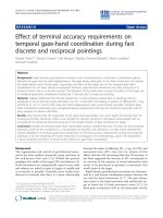
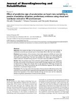
Figure 1a–d shows the SEM images of CNFs prepared at
different sulfur concentrations varies from 10.5 to 40 at.%.
These images clearly show that the morphology of product
is strongly influenced by the atomic ratio of Fe and S. At
10.5 and 40 at.% of Sulfur concentration, the density of as-
grown fiber is lower compare to that of 21 and 31.5 at.%
sulfur grown CNFs. Figure 1b and c depict the SEM images
of as-prepared CNFs grown by using 21 and 31.5 at.% which
indicates that the amount of free soot is very less and
Nanoscale Res Lett (2008) 3:242–248 243
123
diameter of as-prepared CNFs is almost uniform. Moreover,
it can be observed that 21 and 31.5 at.% sulfur grown CNFs
have a smooth surface. However, at 10.5 at.% of sulfur
grown CNFs, soot are observed in large extent. The nanofi-
bers grown from 40 at.% of sulfur, the density is very less and
fibers are quite straight. This might be due to poison of the
iron catalyst which leads to product of low yield.
TEM Analysis
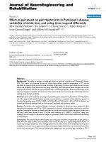
TEM images of as-prepared CNFs grown from 21 to
31.5 at.% of sulfur concentration are shown in Fig. 2.Itis
revealed that decomposition of turpentine oil generates
different kinds of CNFs viz. bamboo like, tubular and sharp
tip geometrical pattern at different sulfur concentration. It
can be clearly seen from TEM images that at lower sulfur
concentration, the as-grown CNFs are relatively thicker
than the CNFs prepared at high sulfur concentration. It is
very clear from TEM analysis that as-grown fibers are
well-graphitized and amorphous carbon coating on the
surface of the CNFs is very less which is also confirmed
from TGA/DTA analysis. The structure of CNFs with
31.5 at.% of sulfur have variable diameter (from 80 to
112 nm) along graphene layer direction as shown in
Fig. 2a. Some of the CNFs are bamboo like with some
transverse bridge forming compartment (Fig. 2b and c) and
very few CNFs contain sharp tip (Fig. 2b). Such CNF with
sharp tip have high expectation for enhanced of field
electron emission. Figure 2d shows as-grown nanofibers
with hemispherical cap. In Fig. 2e, the catalyst particles
were observed at the tip and inside the hollow channel of
CNFs. At the initial stage of the fiber growth process the
catalyst particle flow out of their molten state lead to the
formation of internal hollow channel. Furthermore, near to
the tip of the fiber, molten catalyst particle has been frag-
mented into two parts. Both the fragments have tapered
their bodies so as to grow hollow CNFs in between
themselves. In Fig. 2f, two kinds of graphene arrangement
have been observed. Near to the main fiber axis (shown by
arrow head), graphene sheets are parallel whereas, graph-
ene alignment away from the main axis angled by 50–60°,
shown by rectangle area. In some cases metal particles
were also observed inside the hollow core of CNFs and
core diameter (25 nm) is almost similar to the metal par-
ticle size (Fig. 2g). Here, a few metal particles sit over the
fiber and they are deactivated due to the small layer of
carbon coating. Some of the metal particles remain their
activity alive which is responsible for short in-situ fiber
growth over main fiber platform (Fig. 2h). The graphene
sheets of this short nanofiber are parallel to the main fiber
graphene sheet. Ellipsoid catalyst particle was found at the
tip of this fiber and the diameter of the CNF seems to be
Fig. 1 SEM images of as-
grown CNFs prepared at
different sulfur concentration
(a) 10.5 at.% sulfur (b) 21 at.%
sulfur (c) 31.5 at.% sulfur
(d) 40 at.% sulfur
244 Nanoscale Res Lett (2008) 3:242–248
123
determined by the shape and size of the catalyst particle, as
shown in Fig. 2h. Very few nanofibers are open ended with
outer diameter of 70 nm (Fig. 2i). At lower sulfur con-
centration (21 at.%), we got mostly pipe like structure with
open end and hollow core (Fig. 2k and l).
Raman Spectroscopy
Raman spectroscopy is widely used to characterize the
structural and phase disorder information in carbon related
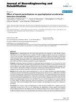
material. Figure 3 shows Raman spectroscopy of the
as-grown CNFs, prepared at different sulfur concentration
by using a green laser with an excitation wavelength of
532 nm and power of 14.4 mW in a range of Raman shift
from 1,100 to 1,800 cm
-1
. Each spectrum was performed
with 30 s acquisition time with an illumination spot size of 1
lm. In the Raman-shift range (1,100–1,800 cm
-1
), two
peaks are observed at approximately 1,345 and 1,573 cm
-1
region, which corresponds to the D- and G-band, respec-
tively. The G-band is attributed to the Raman active E
2g
in-plane oscillation mode and D-band corresponds to the
A
1g
in-plane breathing vibration mode due to structural
defects in the graphite crystal. The rather sharp D and G
band, together with the evident high-frequency shoulder of
Fig. 2 TEM pictures of
31.5 at.% sulfur grown CNFs
(a) CNF with a wide and
variable diameter (b) bamboo-
shaped and sharp tip CNF (c)
CNF with transverse bridge
compartment (d) CNF with
hemispherical cap (e) a 25 nm
CNF with metal particle at the
tip and hollow channel of CNF
(f) two kinds of graphene
arrangement in CNFs (g)a
47 nm CNF with metal particle
inside the hollow core (h)a
short fiber grown over a fiber (i)
open ended CNF with diameter
of 75 nm (j) CNF with
amorphous carbon coating (k)
general overview of 21 at.%
sulfur grown CNF (l) wide
CNF, grown using 21 at.%
of sulfur
Nanoscale Res Lett (2008) 3:242–248 245
123
the G peak, indicate the order and crystallinity of the
CNFs [17, 18]. Relative intensity ratio of D and
G-peaks (Id/Ig) is a measure of amount of disorder in the
CNFs. It is well known that low intensity of D- band rela-
tive to G-band indicates a low amount of amorphous
carbon or lower defect in the CNFs. The Id/Ig value is found
to be * 1 for CNFs prepared at different sulfur concentra-
tion, indicating a large quantity of defects in the CNFs
structure. The defects in the as-grown CNFs are due to the
presence of amorphous carbon coating which is shown in
Fig. 2j.
Thermogravimetric Analysis of As-grown CNFs
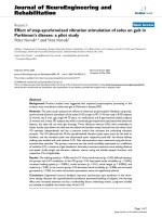
Thermogravimetric analysis and corresponding DTA
curves of as-grown nanofibers are shown in Fig. 4. Detail
study shows that all the fibers grown at different sulfur
concentration mostly show their oxidation temperature at
around 620 °C. This temperature is decomposition tem-
perature of as-prepared carbon nanofibers. The apparent
mass loss below 400 °C is due to mainly oxidation of soot.
At very low sulfur concentration (10.5 at.%) we have got
some oxidation peaks at 400 and 498 °C. We assume that
Fig. 2 continued
246 Nanoscale Res Lett (2008) 3:242–248
123
these peaks are mainly responsible for low diameter nano-
fiber. With increasing sulfur concentration from 21 to 31.5
at.%, DTA maxima shifted towards lower value. This shift
of DTA maxima by changing the sulfur concentration from
21 to 31.5 at.%, is attributed to the lower diameter nanofi-
bers, that has been observed in TEM analysis. The high
diameter and less deformity in fibril structure are less
susceptible to oxidize.
Surface Characteristic Studies of As-grown CNFs
In order to determine the effective surface area of as-grown
nanofibers, nitrogen cryo-adsorption isotherm was carried
out. Figure 5 shows the nitrogen cryo-adsorption isotherm
of CNFs prepared from 31.5 at.% of sulfur concentration.
Monolayer adsorption occurs at low relative pressure
range. At higher relative pressure range (P/P
o
[ 0.7), the
hysteresis loop appears which is responsible for capillary
condensation in the mesopores. The calculated BET sur-
face area was found to be 23.6 m
2
/g. The low surface area
is due to high diameter and the presence of amorphous
carbon coating (Fig. 2j) in the outer wall of as-prepared
CNFs that decreases the porosity of CNFs which is well
evident from TEM analysis.
Role of Sulfur for the Growth of Carbon Nanofibers
The role of sulfur accompanied with transition metal cat-
alyst (Fe, Ni) for the formation of carbon nanofibers has
been observed by several groups [9, 11]. From Fe–S binary
alloys phase diagram it is clear that solubility of sulfur in
Fe is very low, while sulfur can partially react with Fe to
form a FeS–Fe eutectic alloys phase and lower down the
local region surface free energy for the catalytic formation
1100 1200 1300 1400 1500 1600 1700 1800
Raman shift (cm
-1
)
Intensity (arb. units)
S = 40 at.%
S = 31.5 at.% S = 21 at.%
Fig. 3 Raman spectroscopy of carbon nanofibers prepared at differ-
ent sulfur concentration
0
0.2
0.4
0.6
0.8
1
1.2
1.4
1.6
1.8
0 200 400 600 800 1000
Temp [°C]
Temp [°C]
Wt. loss (mg)
TGA
S = 40 at.%
S = 31.5 at.%
S = 21 at.%
S = 10.5 at.%
-300
-250
-200
-150
-100
-50
0
50
0
dV/dT
DTA (uV)
S = 40 at.%
S = 31.5 at.%
S = 21 at.%
S = 10.5 at.%
200400600800
Fig. 4 Thermogravimetric analysis and corresponding derivative
profile of as-prepared CNFs
0
10
20
30
40
50
60
0
P/Po
Quantity adsorbed (cm
3
/g STP)
0.2 0.4 0.6 0.8 1
Fig. 5 Nitrogen adsorption isotherm of 31.5 at.% sulfur grown CNF
Nanoscale Res Lett (2008) 3:242–248 247
123
of CNFs than that of the bare a-Fe phase. In our reaction
condition we have shown the concentration dependent
enhancement and poisoning of Fe catalyst particle in the
growth process of carbon nanofiber by sulfur using tur-
pentine oil as carbon precursor and ferrocene as a dissolved
catalyst. It is well evident that CNFs are susceptible to
nucleate and grow from the molten catalyst surface where
sulfur of 42 at.% concentration effectively reacts with Fe
particle to decrease the melting point of the local region
around 980 °C which is very close to our reaction tem-
perature. This molten state of metal particle catalytically
enhances the dissolution of carbon atom leading to the high
growth of fiber material through VLS mechanism. Cata-
lytic enhancement of growth process with increasing sulfur
concentration reduces the residence time which inhibit the
non catalytic CVD coating or soot formation [9]. At low
sulfur concentration (10.5 at.%) fiber growth is very less
with lot of non-catalytic CVD coating or soot particles.
In our experiment it has been observed that with 21 and
31.5 at.% of sulfur produces carbon nanofibers of higher
yield compare to that of very low and very high concen-
tration of sulfur. At these two intermediate concentration of
sulfur (21 and 31.5 at.%), the surface of the as-grown
carbon nanofibers are very smooth and some amount of
amorphous carbon are occasionally observed which is in
accordance with SEM, TEM and TGA/DTA analysis. The
depression of freezing point of binary alloy system (Fe–S)
has a linear relationship with concentration of sulfur up to a
certain limit. The yield of the carbon nanofiber gradually
increases with increasing sulfur concentration and reaches
to a maxima at 31.5 at.% of sulfur. There is a steady fall of
fiber growth rate at sulfur concentration of 40 at.%. In this
case the amount of CNFs is very low, which is observed
from SEM analysis. This clearly shows that not only the
sulfur has the promoting effect for fiber grown over Fe
catalyst but after a certain limiting concentration it acts as
an inhibitor due to poisoning of catalyst leading to product
of low yield.
Conclusions
Carbon nanofibers with diameters 20–130 nm were grown
successfully when turpentine oil containing ferrocene and
sulfur was used as feedstock in the growth process. The
morphology and yield of the as-grown CNFs strongly
influenced by the concentration of the promoting agent.
The results indicate that addition of sulfur to the ferrocene
catalyst can increase the yield of fiber. Optimum amount of
sulfur have a promoting effect for the growth of CNFs.
However, addition of large quantity of sulfur decreases the
efficiency of the catalyst and only a few CNFs were
formed. In our case, the best results we obtained with sulfur
atomic concentration of 31.5 at.%. The result shows that
turpentine oil is an ideal natural carbon feedstock for
synthesis of CNF. The as-prepared CNFs of different
morphologies may significantly contribute for their poten-
tial applications. The nanofibers containing sharp tip may
exhibit enhanced field emission property and nanofibers
with open ended is possibly benefit to the gas storage.
Acknowledgments One of the authors (Pradip Ghosh) would like to
thank JASSO scholarship, Japan for financial support to carry out this
work. Authors also would like to thank to M. Subramanian for his
kind help.
References
1. C. Park, P.E. Anderson, A. Chambers, C.D. Tan, R. Hidalgo,
N.M. Rodriguez, J. Phys. Chem. B 103, 10572 (1999)
2. G.G. Tibbetts, J.J. McHugh, J. Mater. Res. 14, 2871 (1999)
3. H. Dai, Acc. Chem. Res. 35, 1035 (2002)
4. A. Hoque, M.K. Alam, G.G. Tibbetts, Chem. Eng. Sci. 56, 4233
(2001)
5. T. Kato, K. Kusakabe, S. Morooka, J. Mater. Sci. Lett. 11, 674
(1992)
6. L. Ci, Y. Li, B. Wei, J. Liang, C. Xu, D. Wu, Carbon 38, 1933
(2000)
7. T. Koyama, Carbon 10, 757 (1972)
8. H. Katsuki, K. Matsunaga, M. Egashira, S. Kawasumi, Carbon
19, 148 (1981)
9. G.G. Tibbetts, C.A. Bernardo, D.W. Gorkiewicz, R.L. Alig,
Carbon 32, 569 (1994)
10. F. Benissad-Aissani, H. Aı
¨
t-Amar, M C. Schouler, P. Gadelle,
Carbon 42, 2163 (2004)
11. I. Martin-Gullon, J. Vera, J.A. Conesa, J.L. Gonza
´
lez, C. Merino,
Carbon 44, 1572 (2006)
12. M. Endo, Y.A. Kim, T. Takeda, S.H. Hong, T. Matusita,
T. Hayashi, M.S. Dresselhaus, Carbon 39, 2003 (2001)
13. R.A. Afre, T. Soga, T. Jimbo, M. Kumar, Y. Ando, M. Sharon,
Chem. Phys. Lett. 414, 6 (2005)
14. R.A. Afre, T. Soga, T. Jimbo, M. Kumar, Y. Ando, M. Sharon,
Int. J. Mod. Phys. B 20, 4965 (2006)
15. R.A. Afre, T. Soga, T. Jimbo, M. Kumar, Y. Ando, M. Sharon,
P.R. Somani, M. Umeno, Microporous Mesoporous Mater. 96,
184 (2006)
16. P. Ghosh, T. Soga, R.A. Afre, T. Jimbo, J. Alloys Compd. 462,
289 (2008)
17. M. Chhowalla, K.B.K. Teo, C. Ducati, N.L. Rupesinghe, G.A.J.
Amaratunga, A.C. Ferrari, D. Roy, J. Robertson, W.I. Miline,
J. Appl. Phys. 90, 5308 (2001)
18. A.C. Ferrari, J. Robertson, Phys. Rev. B 61, 14095 (2000)
248 Nanoscale Res Lett (2008) 3:242–248
123