Báo cáo hóa học: " Photocatalytic Degradation of Isopropanol Over PbSnO3 Nanostructures Under Visible Light Irradiation" potx
Bạn đang xem bản rút gọn của tài liệu. Xem và tải ngay bản đầy đủ của tài liệu tại đây (504.2 KB, 7 trang )
NANO EXPRESS
Photocatalytic Degradation of Isopropanol Over PbSnO
3
Nanostructures Under Visible Light Irradiation
Di Chen Æ Shuxin Ouyang Æ Jinhua Ye
Received: 12 November 2008 / Accepted: 17 December 2008 / Published online: 7 January 2009
Ó to the authors 2009
Abstract Nanostructured PbSnO
3
photocatalysts with
particulate and tubular morphologies have been synthe-
sized from a simple hydrothermal process. As-prepared
samples were characterized by X-ray diffraction, Bru-
nauer–Emmet–Teller surface area, transmission electron
microscopy, and diffraction spectroscopy. The photoac-
tivities of the PbSnO
3
nanostructures for isopropanol (IPA)
degradation under visible light irradiation were investi-
gated systematically, and the results revealed that these
nanostructures show much higher photocatalytic properties
than bulk PbSnO
3
material. The possible growth mecha-
nism of tubular PbSnO
3
catalyst was also investigated
briefly.
Keywords Nanostructures Á Photocatalysts
Introduction
Since the Honda–Fujishima effect was reported in 1972,
considerable efforts have been paid to develop semicon-
ductor photocatalysts for water splitting and degradation of
organic pollutants in order to solve the urgent energy and
environmental issues [1–9]. However, to date, most of the
photocatalysts reported only respond to UV light irradiation
(\420 nm). For visible light accounts for about 43% of the
solar spectrum, the utilization of visible light is more sig-
nificant than UV light and thus developing visible light-
driven photocatalyst is one of the most important and
meaningful subjects in this field. The fundamental steps for
photocatalytic reaction of oxide semiconductor mainly
include the following processes: (i) the generation of pho-
toexited charges in the semiconductor materials, (ii) the
separation and migration of the generated charges without
recombination, and (iii) the redox reaction on the surface of
the semiconductor. The first and second steps are associated
with the electronic structures of the oxide semiconductor,
while the third step is strongly relevant to the surface
properties of the catalyst [10–12].
Generally, the improvement of surface area always
contributes to more reaction sites, which is beneficial to the
photocatalytic reaction. With particular microstructures,
nanomaterials have recently gained much attention to be
used as high-performance photocatalysts with enhanced
photocatalytic activities. For example, in our previous
work, we reported the synthesis of perovskite SrSnO
3
nanostructures [13] from a facile hydrothermal method.
Compared with the catalyst from the traditional solid state
route, nanostructured SrSnO
3
catalysts with larger surface
areas showed higher photocatalytic activities for water
splitting under UV light irradiation. Undoubtedly, the
enhanced photocatalytic activities are mainly attributed to
the increased surface areas, which are believed to be one of
the efficient approaches to enhance the activity of catalysts.
From a similar hydrothermal process, we reported here the
preparation of a new visible light-responded photocatalyst,
PbSnO
3
nanostructures including particulate and tubular
shapes. Experimental results confirmed that these nano-
structures show distinguished photocatalytic oxidation
activity upon mineralizing isopropanol (IPA) into CO
2
in
the visible light region.
D. Chen Á S. Ouyang Á J. Ye (&)
International Center for Materials Nanoarchitectonics (MANA)
and Photocatalytic Materials Center (PMC), National Institute
for Materials Science (NIMS), 1-2-1 Sengen, Tsukuba,
Ibaraki 305-0047, Japan
e-mail:
D. Chen
e-mail:
123
Nanoscale Res Lett (2009) 4:274–280
DOI 10.1007/s11671-008-9237-y
Experimental Section
Synthesis of PbSnO
3
Nanostructures
For the synthesis of tubular PbSnO
3
nanostructures, two
same surfactant–water solutions were first prepared by
dissolving 0.2 g poly(vinyl pyrrolidone) (PVP) surfactant
in 25 mL distilled water, respectively. Then, equivalent
amounts of Pb(AC)
2
and Na
2
SnO
3
(2 mmol) were dis-
solved in the above surfactant–water solution at room
temperature, separately. After stirred for 30 min, the
solutions were mixed together and kept stirring for another
30 min, which were then transferred into a Teflon-lined
stainless steel autoclave and subsequently heated at 180 °C
for 16 h in an oven. After cooling to room temperature, the
yellow precipitate was filtered and washed for several
times with distilled water and ethanol, respectively, then
dried in air at 70 °C. PbSnO
3
nanoparticles were also
synthesized in this work using a similar process without the
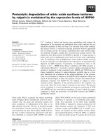
use of surfactant PVP. Brief flowcharts illustrating the
formation of PbSnO
3
nanostructures are shown in
Scheme 1.
Synthesis of Bulk PbSnO
3
from SSR
To compare the photocatalytic properties, bulk PbSnO
3
was also synthesized by selecting optimal experimental
parameters including calcinations temperature and time.
For the synthesis of PbSnO
3
bulk material, we first dis-
solved equivalent amounts of Pb(AC)
2
and Na
2
SnO
3
into
distilled water under stirring, and then mixed them to
obtain the white precursor. Heating the white precursor at
500 ° C for 5 h in a quartz tube under Ar flow resulted in
yellow powders. In this process, temperature is very
important for the formation of yellow powders due to the
instability of PbSnO
3
at high temperature.
Characterization
The crystal structure of the as-prepared sample was con-
firmed by the X-ray diffraction pattern (JEOL JDX-3500
Tokyo, Japan). The morphology and size of the sample
were characterized by transmission electron microscope
(HRTEM, JEM-3000F) equipped with an X-ray dispersive
spectrometer (EDS). UV–Vis diffuse reflectance spectra
were recorded on a UV/Vis spectrometer (UV-2500, Shi-
madzu) and were converted from reflection to absorbance
by the standard Kubelka–Munk method. The surface area
of the sample was measured by the BET method (Shimadsu
Gemini Micromeritics).
Evolution of Photocatalytic Property
The photoactivities of the obtained PbSnO
3
nanostructures
were evaluated by decomposition of gaseous IPA under
visible light irradiation. Typically, 0.1 g PbSnO
3
catalyst
was spread uniformly in a quartz-made vessel with an
irradiation area of 7.8 cm
2
. Prior to light irradiation, the
vessel was kept in dark for 2 h until an adsorption–
desorption equilibrium was finally established. The visible
light with light intensity of about 1.8 mW/cm
2
was
obtained by using a 300 W Xe lamp with a set of combined
filters (L42 ? B390 ? HA30) and a water filter. The
products in the gas phase were analyzed with a gas chro-
matograph system (GC-14B, Shimadzu, Japan), using a
flame ionization detector (FID) for organic compounds
determination.
Results and Discussion
Crystal Structure and Morphology
The crystal structure of both as-synthesized PbSnO
3
nanostructures from the hydrothermal process and bulk
material from the solid-state route were characterized by
XRD and the results are shown in Fig. 1. In these patterns,
all peaks can be indexed as cubic phase PbSnO
3
with py-
rochlore-type structure (space group: Fd3m). The
calculated lattice constant a = 10.67 A
˚
is in agreement
with previously reported value (JCPDS 17-060). From the
XRD patterns, it can be clearly seen that the PbSnO
3
nanostructures are of better crystallinity than the bulk
material, which might be one of the reasons why nano-
structured PbSnO
3
show higher photocatalytic activities
(detailed contents in the part of discussion). Inset in Fig. 1
is a typical SEM image of the product from the SSR.
Scheme 2 shows the crystal structure of pyrochlore-type
PbSnO
3
, an anion-deficient three-dimensional framework
consisting of corner-sharing SnO
6
octahedra.
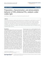
Figure 2a shows a TEM image of as-prepared PbSnO
3
nanoparticles from the hydrothermal process. Obviously,
the products are consisted of many small nanoparticles with
dimensions in the range of 10–15 nm. The corresponding
Scheme 1 Flowchart for preparing PbSnO
3
nanostructures by the
hydrothermal process
Nanoscale Res Lett (2009) 4:274–280 275
123
selected-area electron diffraction (SAED) pattern (Fig. 2b)
can be readily indexed as cubic phase PbSnO
3
, which is in
agreement with the XRD result. An EDS spectrum in
Fig. 2c depicts the presence of Pb, Sn, and O elements,
indicating the formation of PbSnO
3
. In this spectrum, the
signals corresponding to Cu arise from the TEM grid. The
microstructures of the produced PbSnO
3
nanoparticles were
investigated using high-resolution TEM. As indicated in
Fig. 2d, the nanoparticles are well-crystallized and of good
crystallinity. The marked lattice fringes of 0.32 and
0.25 nm correspond well to the (311) and (331) crystalline
planes of cubic PbSnO
3
.
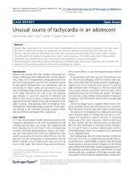
In the presence of surfactant PVP, polycrystalline
PnSnO
3
nanotubes were obtained instead of nanoparticles.
Panels (a) and (b) of Fig. 3 are typical TEM images of
as-obtained PnSnO
3
nanotubes, which reveal that the
nanotubes are polycrystalline with typical diameters of
300–340 nm and wall thickness of 40–80 nm. Figure 3cis
the corresponding SAED pattern taken from a single
PbSnO
3
nanotube, confirming the formation of polycrys-
talline nanotube. The three polycrystalline rings are in
accordance with those of (311), (400), and (533) of cubic
phase PbSnO
3
. Typical HRTEM images of the nanotubes
are shown in Fig. 3d and e. It can be seen that the poly-
crystalline PbSnO
3
nanotubes are composed of numerous
nanoparticles with diameters of several to ten nanometers.
The interplanar spacing was calculated to be about
0.32 nm, corresponding to the (311) plane of cubic
PbSnO
3
, in accordance with the SAED result.
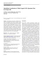
UV–Vis spectra of all three PbSnO
3
samples were
checked and the spectra are displayed in Fig. 4. It is evi-
dent that PbSnO
3
nanostructures could absorb much more
visible light than bulk sample at the present condition.
Corresponding band gaps of PbSnO
3
are determined to be
2.8 eV for bulk material, 2.8 eV for nanotubes, and 2.7 eV
for nanoparticles from the absorption edges, respectively
(as shown in Table 1).
Growth Mechanism
One-dimensional micro- or nanosized tubular materials
with hollow interior structure have attracted extraordinary
attention owing to their unique properties and potential
applications [14–16]. Many kinds of growth mechanisms
have been proposed for the formation of nanotubes. For
example, the rolling mechanism and template-assisted
mechanism have been reported to explain the formation of
tubular structure with layered or pseudo-layered structures
such as BN [17], NiCl
2
[18], Nb
2
O
5
[19], Se [20], etc.
During the growth of PbSnO
3
nanotubes, surfactant PVP
was used and was found to be the key issue for nanotube
growth. Thus, the surfactant-assisted growth process can be
used to explain the formation of these nanotubes. The
possible formation process of PbSnO
3
nanotubes may
involve three following distinctive stages: (i) the genera-
tion of PbSnO
3
particles, (ii) the adsorption of PVP
molecules on the surface of particles and subsequently self-
assembly into tubular microstructure, and (iii) the forma-
tion of uniform PbSnO
3
nanotubes. In the initial stage,
cubic PbSnO
3
tiny nuclei could easily crystallize and serve
as the seeds for the growth of nanotubes. Meanwhile, PVP
molecules in the solution would strongly and rapidly
adsorb on the surfaces of these nascent nuclei, which
confined the crystal growth and efficiently controlled the
dimension and morphology of the final products. Then,
these particles with high free energy aggregated and self-
assembled into tubular structures with the help of PVP
template molecules. As a result, the growth of PbSnO
3
nanotubes would form eventually by a typical oriented
Fig. 1 XRD patterns of the as-prepared PbSnO
3
nanostructures from
the hydrothermal route and bulk samples from the solid-state route,
respectively. Inset shows SEM image of bulk material from SSR
Scheme 2 Crystal structure of pyrochlore PbSnO
3
276 Nanoscale Res Lett (2009) 4:274–280
123
attachment process under the hydrothermal conditions.
Meanwhile, the existence of PVP in this solution can alter
the surface energies of various crystallographic surfaces to
promote selective anisotropic growth of nanocrystals [21].
Photocatalytic Degradation of IPA
The photocatalytic activities of the PbSnO
3
nanostructures
were evaluated by IPA mineralization under visible light
irradiation. Under visible light irradiation, gaseous IPA was
gradually oxidized through an acetone intermediate to CO
2
,
and the concentration changes of IPA, acetone, and CO
2
versus time over PbSnO
3
nanoparticles are shown in Fig. 5.
It was clear that the concentration of IPA in the reaction
system almost decreased from the initial concentration to
zero; the concentration of acetone also decreased contin-
ually while the concentration of CO
2
increased with the
long-term irradiation. Inset in Fig. 5 shows that almost no
additional CO
2
gas was detected under dark test, suggest-
ing that degradation of IPA over the catalyst was driven by
light irradiation. Figure 6 further displays the concentration
changes of evolved acetone over different PbSnO
3
nano-
structures and bulk material with the increasing of
irradiation time. Clearly, acetone was detected over all
these catalysts when light was turned on. Among them,
particulate PnSnO
3
performs the best activity for degra-
dation of IPA under the present conditions.
In this case, the photocatalytic activities for IPA deg-
radation over these catalysts were in the order of
nanoparticle [ nanotube [ bulk material, which was in
consistent with that of BET surface areas. As mentioned
earlier, BET surface area of catalyst is closely related to its
photoactivity. Usually, larger surface area means much
more active sites, at which the photocatalytic reaction
occurs. Thus, as shown in Table 1, PbSnO
3
nanostructures
with larger surface areas as 68 m
2
/g for nanoparticles and
50 m
2
/g for nanotubes, respectively, resulted in enhanced
photocatalytic activities than bulk material with 10 m
2
/g of
surface area. Meanwhile, the improved crystallinity of
PbSnO
3
nanostructures (shown in XRD patterns) resulted
in the increase of photocatalytic activity since it could
reduce electron-hole recombination rate.
The wavelength dependence of the rate of acetone
evolution from IPA degradation over PbSnO
3
nanoparticles
was investigated by using different cutoff filters, as shown
in Fig. 7. The intensity variation of the incident light with
different cutoff filters is given as an inset figure for refer-
ence. It is notable that the rate of acetone evolution
decreased with increasing cutoff wavelength, which is in
good agreement with the UV–Vis diffuse reflectance
Fig. 2 a TEM image; b SAED
pattern; c EDS spectrum;
d HRTEM image of the
as-prepared PbSnO
3
nanoparticles from the
hydrothermal process
Nanoscale Res Lett (2009) 4:274–280 277
123
spectra of PbSnO
3
nanoparticles, indicating the present
reaction is driven by a visible light absorption. The used
catalysts were again checked by XRD and UV–Vis
reflectance spectroscopy to explore the stabilities of
samples. There was no detectable change between the
spectra of PbSnO
3
before and after the photodegradation of
IPA gas, suggesting that the catalyst was fairly stable for
the degradation of organic compounds. For many p-block
metal oxides photocatalysts with d
10
configuration, the VB
and CB are the 2p orbital of the oxygen atom and the
lowest unoccupied molecular orbital (LUMO) of p-block
metal center, respectively [22–24]. Meanwhile, for the
lead-containing compounds, it was found that an additional
hybridization of the occupied Pb 6s and O 2p orbitals
seems to push up the position of the valence band and
result in a narrower band gap [25]. Based on the above
depiction, we assumed that the VB of PbSnO
3
is composed
of hybridized Pb 6s and O 2p orbitals, whereas the CB is
composed of Sn 5s orbitals, and these bands meet the
potential requirements of organic oxidation.
Fig. 3 a, b TEM images; c
SAED pattern; d, e HRTEM
images of the as-prepared
PbSnO
3
nanotubes in the
presence of surfactant PVP
Fig. 4 UV–Vis diffuse reflectance spectra of PbSnO
3
nanostructures
from the hydrothermal route and PbSnO
3
particles from the solid-state
route, respectively
Table 1 Physical and photocatalytic properties of PbSnO
3
samples
Sample Band gap (eV) BET (m
2
/g) Rate of acetone (ppm/h)
NP 2.7 68 42.2
NT 2.8 50 18.5
Bulk
a
2.8 10 5.1
a
Bulk PbSnO
3
are prepared from the solid-state route
278 Nanoscale Res Lett (2009) 4:274–280
123
Conclusion
In summary, we have successfully synthesized pure phase
PbSnO
3
nanoparticles and nanotubes from the facile
hydrothermal process at low temperature. The surfactant
PVP used as the capping reagent plays a crucial role in the
formation of tubular PbSnO
3
structure. PbSnO
3
nano-
structures with better crystallinity and larger surface areas
show enhanced photocatalytic activity for the decomposi-
tion of organic pollutant isopropanol under the visible light
irradiation than the catalyst prepared by the solid-sate
method.
Acknowledgment This work was partially supported by the Global
Environment Research Fund from the Ministry of Education, Culture,
Sports, Science and Technology (MEXT) of the Japanese Govern-
ment. This work was also supported the World Premier International
Research Center Initiative (WPI Initiative) on Materials Nanoarchi-
tectonics, MEXT, Japan and the Strategic International Cooperative
Program, Japan Science and Technology Agency (JST).
References
1. A. Fujishima, K. Honda, Nature 238, 37 (1972). doi:10.1038/
238037a0
2. T. Kawai, T. Sakata, Nature 286, 474 (1980). doi:10.1038/
286474a0
3. M.R. Hoffmann, S.T. Martin, W. Choi, Chem. Rev. 95,69
(1995). doi:10.1021/cr00033a004
4. C.C. Wong, W. Chu, Environ. Sci. Technol. 37, 2310 (2003). doi:
10.1021/es020898n
5. W. Ho, J. Yu, J. Lin, P. Li, Langmuir 20, 5865 (2004). doi:
10.1021/la049838g
6. M.A. Fox, M.T. Dulay, Chem. Rev. 3, 341 (1993). doi:10.1021/
cr00017a016
7. Z.G. Zou, J.H. Ye, K. Sayama, H. Arakawa, Nature 414, 625
(2001). doi:10.1038/414625a
8. J. Sato, S. Saito, H. Nishiyama, Y. Inoue, J. Phys. Chem. B 105,
6061 (2001). doi:10.1021/jp010794j
9. J. Sato, S. Saito, H. Nishiyama, Y. Inoue, J. Photochem. Photo-
biol. Chem. 148, 85 (2002). doi:10.1016/S1010-6030(02)
00076-X
10. H.B. Fu, C.S. Pan, W.Q. Yao, Y.F. Zhu, J. Phys. Chem. B 109,
22432 (2005). doi:10.1021/jp052995j
11. H.L. Xu, W.Z. Wang, W. Zhu, J. Phys. Chem. B 110, 13829
(2006). doi:10.1021/jp061934y
12. J.Q. Yu, A. Kudo, Adv. Funct. Mater. 16, 2163 (2006). doi:
10.1002/adfm.200500799
13. D. Chen, J.H. Ye, Chem. Mater. 19(18), 4585 (2007). doi:
10.1021/cm071321d
14. D.R. Bae, S.J. Lee, S.W. Han, J.M. Lim, D.M. Kang, J.H. Jung,
Chem. Mater. 20, 3809 (2008). doi:10.1021/cm703674d
Fig. 5 Changes of IPA, acetone, and CO
2
concentrations as a
function of time in the presence of PbSnO
3
nanoparticles from the
hydrothermal process under visible light irradiation (catalyst: 0.1 g,
300 W Xe lamp, 420 nm cutoff filter and water filter). Inset shows
that no CO
2
gas was evolved turning off the light
Fig. 6 Acetone evolution from IPA photodegradation over serious
PbSnO
3
samples (catalyst: 0.1 g, 300 Xe lamp, L42 ? B390 ? HA30
and water filter)
Fig. 7 Wavelength dependence of acetone evolution from isopropa-
nol photodegradation on the cutoff wavelength of incident light, and
UV–Vis diffuse reflectance spectrum of PbSnO
3
samples. The inset
shows the wavelength dependence of light intensity with
different cutoff filters (catalyst: 0.1 g, 300 W Xe lamp, 400 nm \
k \500 nm)
Nanoscale Res Lett (2009) 4:274–280 279
123
15. T.W. Ebbesen, P.M. Ajayan, Nature 358, 220 (1992). doi:
10.1038/358220a0
16. B. Chi, E.S. Victorio, T. Jin, Chem. Lett. 35, 350 (2006). doi:
10.1246/cl.2006.350
17. N.G. Chaopra, R.J. Luyken, K. Cherrey, V.H. Crespi, M.L.
Cohen, S.G. Louie, A. Zettl, Science 269, 966 (1995). doi:
10.1126/science.269.5226.966
18. Y.R. Hacohen, E. Grunbaum, R. Tenne, J. Sloan, J.L. Hutchison,
Nature 295, 336 (1998). doi:10.1038/26380
19. Y. Kobayashi, H. Hata, M. Salama, T.E. Mallouk, Nano Lett. 7,
2142 (2007). doi:10.1021/nl0708260
20. Y.R. Ma, L.M. Qi, J.M. Ma, H.M. Cheng, Adv. Mater. 16, 1023
(2004). doi:10.1002/adma.200400071
21. S.H. Yu, B. Liu, M.S. Mo, J.H. Huang, X.M. Liu, Y.T. Qian,
Adv. Funct. Mater. 13, 639 (2003). doi:10.1002/adfm.200304373
22. J.M. Herrmann, J. Disdier, P. Pichat, J. Catal. 113, 72 (1988). doi:
10.1016/0021-9517(88)90238-2
23. D.S. Muggli, L. Ding, M.J. Odland, Catal. Lett. 78, 23 (2002).
doi:10.1023/A:1014954114655
24. X.Z. Li, F.B. Li, Environ. Sci. Technol. 35, 2381 (2001). doi:
10.1021/es001752w
25. H.G. Kim, O.S. Becker, J.S. Jang, S.M. Ji, P.H. Borse, J.S. Lee,
J. Solid State Chem. 179, 1214 (2006). doi:10.1016/j.jssc.2006.
01.024
280 Nanoscale Res Lett (2009) 4:274–280
123