Báo cáo hóa học: " Characterization and Optical Properties of the Single Crystalline SnS Nanowire Arrays" pot
Bạn đang xem bản rút gọn của tài liệu. Xem và tải ngay bản đầy đủ của tài liệu tại đây (389.46 KB, 5 trang )
NANO EXPRESS
Characterization and Optical Properties of the Single Crystalline
SnS Nanowire Arrays
G. H. Yue Æ L. S. Wang Æ X. Wang Æ
Y. Z. Chen Æ D. L. Peng
Received: 28 October 2008 / Accepted: 8 January 2009 / Published online: 23 January 2009
Ó to the authors 2009
Abstract The SnS nanowire arrays have been success-
fully synthesized by the template-assisted pulsed
electrochemical deposition in the porous anodized alumi-
num oxide template. The investigation results showed that
the as-synthesized nanowires are single crystalline struc-
tures and they have a highly preferential orientation. The
ordered SnS nanowire arrays are uniform with a diameter
of 50 nm and a length up to several tens of micrometers.
The synthesized SnS nanowires exhibit strong absorption
in visible and near-infrared spectral region and the direct
energy gap E
g
of SnS nanowires is 1.59 eV.
Keywords SnS nanowires Á Pulse electrodeposition Á
Optical properties
Introduction
Semiconductor nanostructures have been attracting world-
wide attention due to their exceptional electrical, optical,
and magnetic properties, and their potential applications in
nanoscale electronics, photonics, and functional materials
as well [1–3]. Among them, tin sulfide (SnS) has sparked
intensive interest for its semiconducting and optical
properties. SnS, as one of the important IV–VI group
semiconductors, exhibits both the p- and n-type conduction
[4], has an energy band gap of about 1.3 eV [5]. Normally,
SnS is composed of double layers of tightly bound Sn–S
atoms and the bonding between layers are extremely weak
Van der Vaals forces, which has an orthorhombic structure
[6]. Additionally, SnS has the advantage of its constituent
elements being abundant in nature and not posing any
health and environmental hazards. Therefore, SnS has a big
potential to be used as solar absorber in a thin film solar
cell and near-infrared detector [4, 5], as photovoltaic
materials [7], and as a holographic recording medium [8].
Therefore, single crystalline SnS nanowires reported in this
paper are expected to offer enhanced properties. Therefore,
it is important to investigate practical synthesis routes for
novel SnS nanostructures, especially in single crystalline.
Crystalline tin sulfides have been prepared by a variety
of methods, such as direct vapor transport method [9],
stoichiometric composition technique [10], physical vapor
transport method [11], and Bridgman–Stockbarger tech-
nique [12]. In recent years, thin films of SnS have been
investigated widely due to their applications in photovol-
taic and photoelectrochemical solar cells. SnS thin films
have been prepared by spray pyrolytic deposition [13],
electrochemical deposition [4, 5], chemical vapor deposi-
tion [14, 15], and chemical bath deposition [16]. To our
knowledge, preparation of novel wire-like SnS nanostruc-
tures has been reported sparsely. Panda et al. [17] has
reported surfactant-assisted synthesis of SnS nanowires
grown on tin foils and SnS nanorods were reported by
Biswas et al. [18]. We had used the anodic aluminum oxide
(AAO) template synthesized from some metal sulfide
nanowire arrays [19, 20] and in this paper, we have pre-
sented single crystalline SnS nanowires prepared by
template-assisted electrochemical deposition.
G. H. Yue Á L. S. Wang Á X. Wang Á Y. Z. Chen Á
D. L. Peng (&)
Department of Materials Science and Engineering, Research
Center of Materials Design and Applications, Xiamen
University, Xiamen 361005, People’s Republic of China
e-mail:
G. H. Yue
e-mail:
123
Nanoscale Res Lett (2009) 4:359–363
DOI 10.1007/s11671-009-9253-6
Experimental
The highly ordered porous AAO films were prepared by
anodizing an aluminum foil (99.999%) in an acid solution
using a two-step anodizing process, which could be seen in
the Refs. [19–22].
A three-electrode cell was used for pulse electrochem-
ical deposition: a saturated calomel electrode (SCE) as the
reference electrode, an AAO template with aluminum
substrate as the working electrode (cathode), and a plati-
num sheet as the contrary electrode (anode). The deposition
area was about 1 9 2cm
2
. An aqueous bath containing
30 mM SnCl
2
and 100 mM Na
2
S
2
O
3
was used. The pH
value of the solution was around 1.8 before deposition. The
temperature of the solution was kept at 10 °C. The
potential applied to the cathode was pulsed-form, its ‘‘on’’
potential V
on
was 10 V and ‘‘off’’ potential V
off
was 0 V,
both ‘‘on’’ time and ‘‘off’’ time were 10 s in all the voltage
conditions. More details of the experiment can be seen in
the Refs. [4, 20, 21]. Deposition period was 5 min. After
deposition experiment, the deposited sample was washed
softly in pure water, and naturally dried in air. All the
chemicals used were analytical grade reagents and the
water used was deionized distilled water.
The phase purity of as-synthesized product was exam-
ined by X-ray diffraction (XRD) using Rigaku Rint-2000
diffractometer with monochromatized CuK
a
radiation
(k = 0.15405 nm). The nano/microstructure of the SnS
product was further observed by transmission electron
microscope (TEM) and field-emission scanning electron
microscope (FESEM) with an energy dispersive spec-
trometer (EDS) analysis attachment, which were performed
on a Hitachi Model H-800 (200 kV) and a field-emission
microscope (S-4800, 15 kV), respectively. The high reso-
lution transmission electron microscope (HRTEM) image
and the corresponding selected area electron diffraction
(SAED) pattern were taken by a JEOL-2010 TEM with an
accelerating voltage of 200 kV. UV–VIS–NIR absorption
spectra were measured at room temperature with a Cary
5000 UV–VIS–NIR spectrometer.
Results and Discussion
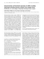
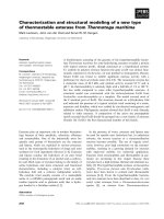
The typical XRD pattern of the sample which etched for
5 h is shown in Fig. 1. The peaks at about 30.44°, 32.06°,
54.42°, and 64.14° were assigned to (101), (040), (240),
and (212) diffraction of orthorhombic SnS, respectively.
All the peaks can be indexed to orthorhombic SnS
with lattice constants: a = 4.34 A
˚
,b= 11.14 A
˚
, and
c = 3.96 A
˚
, which is in good agreement with the values
from the standard card (JCPDS No. 39-0354). The strong
and sharp diffraction peaks indicate that the product is well
crystallized. It can be seen that the major peak (101) is
strongly dominating other peaks indicating the preferred
orientation. The sharp and narrow (101) peaks indicate that
the nanowires are highly crystalline and consist of only a
single compositional phase. XRD analysis detected no
impurities such as SnO
2
and SnS
2
.
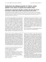
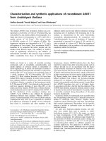
Figure 2a shows a typical SEM micrograph of the AAO
template, anodized using 0.3 M H
2
SO
4
electrolyte at 0 °C
and a voltage of 20 V. It was found that the nanopores of
the AAO template are uniform and highly ordered with
average diameters of 50 ± 4 nm and the interpore distance
is about 30 nm. In addition, the varied diameters and
lengths of nanopores can be obtained by adjusting the
varied acid, anodizing time, and anodizing temperature.
Figure 2b–d show the SEM images of SnS nanowires
grown in AAO template. These photographs indicate that
the nanowires are uniformly distributed, highly ordered,
and parallel to each other. Few microscopic defects are
found in these wires. Figure 2b, c is a planform, from
which we can find several clusters of nanowires. The
clusters may result from the situation that the nanowires do
not cover by the framework of AAO template but stand
free incompletely. When the alumina on the top of AAO
template is dissolved away, the nanowires that embedded
in the template are released gradually and incline to
agglutinate together. It is conceivable that the surface
energy of these nanowires causes this interesting phe-
nomenon. Figure 2b also shows that SnS nanowires are
abundant, uniform, and highly ordered in the large area.
Figure 2d reveals a cross-section where the alumina matrix
of the AAO template has been partially dissolved away. It
can be seen that the nanowires deposited inside the nano-
channel of the AAO template are parallel, tidily aligned,
20 40 60 80
(040)
Intensity
2 Theta (de
g
.)
(101)
(212)
(240)
Fig. 1 XRD patterns of the SnS nanowire arrays after etching time of
5h
360 Nanoscale Res Lett (2009) 4:359–363
123
and uniformly distributed. It is correlative to that the AAO
template had an array of densely parallel nanoholes
arranged in a hexagonal form. From these figures it can be
estimated that the length of the nanowires is about several
tens of micrometers. It corresponds with the thickness of
the AAO template which we used.
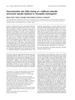
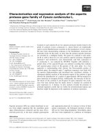
TEM images of SnS nanowires formed within the AAO
template are shown in Fig. 3a, b. Figure 3a shows that the
SnS nanowires cross and overlap with each other, and
Fig. 3b shows that the diameter of the SnS nanowires is
about 50 nm. It’s diameter is approximately equal to that of
the nanochannels of the employed AAO template. These
nanowires are uniformly distributed, which indicates that
the alumina matrix is dissolved completely. The nano-
structure of the SnS nanowires was further investigated
with SAED. The SAED pattern (Fig. 3c) taken from a
single nanowire, indicates that the SnS nanowires are a
good single crystalline. The HRTEM image of a single SnS
Fig. 2 SEM images of AAO
template and SnS nanowire
arrays. a Typical SEM image of
AAO template. b and c The top
view in a low magnification. d
SEM image of a typical cross-
section
Fig. 3 TEM images of AAO
template and SnS nanowire
arrays. a The sample was etched
for 10 h. b The SnS nanowires
with a diameter of about 50 nm.
c The SAED pattern taken from
the nanowires in (b). d The
HRTEM image of the SnS
nanowires in (b)
Nanoscale Res Lett (2009) 4:359–363 361
123
nanowire is given in Fig. 3d. Seen from this image, the
lattice fringes of the SnS are clear and uniform, and
additionally it confirmed that these single crystalline SnS
nanowires are of high quality. The measured spacing of the
crystallographic planes shown in Fig. 3dis0.295 nm,
corresponding to the value of (101) planes of the ortho-
rhombic SnS nanowires.
Energy dispersive spectrometer (EDS) analysis reveals
that the product is composed of stannum and sulfur, and the
ratio of the S atom and Sn atom is 1:0.985, which just
accords with the stoichiometric ratio of SnS.
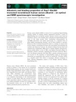
The representative optical absorption spectrum of the
SnS nanowires synthesized by template-assisted electro-
chemical deposition is shown in Fig. 4a. This figure
indicated that the SnS nanowires have high absorption in
the range of ultraviolet, and the absorption coefficient is
above the 70%. The absorption reduces rapidly with the
increase in the wavelength, and the absorption is very small
or becomes zero when the wavelength is above 800 nm.
The absorption coefficient a, of SnS nanowires, was cal-
culated from the average absorption index (A)as
a ¼ 4pA=k [23]. The spectral behavior of absorption
coefficient as a function of energy, hv, is shown in Fig. 4b.
SnS nanowires have high absorption coefficient
([10
5
cm
-1
) in the wavelength range from 400 to 800 nm.
To determine the energy band gap, E
g
, and the type of
optical transition responsible for this intense optical
absorption, and the absorption spectrum was analyzed
using the equation for the near-edge absorption [4, 5].
ðahmÞ
n
¼ Aðhm ÀE
g
Þ
where, A is a constant and n characterizes the transition
process. We can see n = 2 and 2/3 for direct allowed and
forbidden transitions, respectively, and n = 1/2 and 1/3 for
indirect allowed and forbidden transitions, respectively.
Figure 5 shows curves of (ahm)
2
versus hm of the SnS
nanowires. The curve has a good straight line fit with
higher energy range above the absorption edge, indicating a
direct optical transition near the absorption edge. Based on
Fig. 5, the direct energy gap E
g
of the sample has been
calculated as 1.59 eV, which is higher than the literature
value of SnS bulk or films [4, 5, 13, 16]. The increased
band gap values of SnS nanowires which was compared to
the bulk material, do not manifest quantum size effects.
However, the estimated average single crystal nanowire
diameter was 50 nm. The absence of size quantization
effects may be attributed to the very small Bohr radius for
the SnS. And it is well-known that Bohr radius of SnS
should be smaller than 7 nm. The nanowires diameter is far
greater than the Bohr radius and it can be suggested that the
increased band gap values do not manifest quantum size
effects [24, 25]. The energy band gap at 1.59 eV detected
in our previous study may be attributed to the surface effect
of the carriers in the semiconductor nanowires. The lattice
distortion inducing a smaller lattice constant or surface
lattice defects will lead to a size dependent enlargement of
400 500 600 700 800 900 1000
0.0
0.2
0.4
0.6
0.8
Absorption
Wavelength (nm)
1.0 1.5 2.0 2.5 3.0 3.5
0.0
5.0x10
4
1.0x10
5
1.5x10
5
2.0x10
5
2.5x10
5
3.0x10
5
α (cm
-1
)
hv (eV)
(a)
(b)
Fig. 4 Optical properties of SnS nanowires: a is the optical
absorption spectrum and b is the dependence of absorption coefficient
on photon energy
1.0 1.5 2.0 2.5 3.0 3.5
0.0
0.5
1.0
1.5
2.0
2.5
3.0
(
αhv)
2
hv (eV)
Fig. 5 The curves of (ahm)
2
vs. hm for the SnS nanowires
362 Nanoscale Res Lett (2009) 4:359–363
123
the band gap, which results in a blue shift in the absorbance
onset, as observed in this work.
Conclusion
The low-toxicity SnS nanowire arrays have been success-
fully synthesized using the template-assisted pulsed
electrochemical deposition in the AAO template. The XRD
pattern indicates that the nanowires are composed of SnS
phase and have a highly preferential (101) orientation. The
sample obtained in our experiment forms a stable ortho-
rhombic superstructure. The TEM images show that the
diameter of the SnS nanowires is about 50 nm and length
up to several tens of micrometers. The SAED shows that
the product is single crystalline structure. EDS result
indicates that the ratio of S atom and Sn atom in our
samples is 1:0.985, which just accords with the stoichi-
ometric ratio of SnS. The synthesized SnS nanowires
exhibit strong absorption in the visible and near-infrared
spectral region. The direct energy gap E
g
of the SnS
nanowires has been calculated as 1.59 eV, and this
experimental optical band gap value is the evidence for the
quantum confinement of the SnS nanowires.
Acknowledgments This work was partially supported by the
National Outstanding Youth Science Foundation of China (No.
50825101), and the National Natural Science Foundation of China
(No. 50671087). The correspondence author (D. L. Peng) acknowl-
edges the Minjiang Chair Professorship Program released by Fujian
Province of P.R. China for financial support.
References
1. X. Duan, Y. Huang, R. Agarwal, C.M. Lieber, Nature 421, 241
(2003). doi:10.1038/nature01353
2. G.H. Yue, P.X. Yan, D. Yan et al., Appl. Phys. A 84, 409 (2006).
doi:10.1007/s00339-006-3643-8
3. M.S. Fuhrer, J. Nygard, L. Shih et al., Science 288, 494 (2000).
doi:10.1126/science.288.5465.494
4. G.H. Yue, D.L. Peng et al., J. Alloy Compd. (2008). doi:10.1016/
j.jallcom.2008.01.047
5. G.H. Yue, W. Wang et al., J. Alloy Compd. (2008). doi:10.1016/
j.jallcom.2008.06.105
6. A. Ghazali, Z. Zainal, M.Z. Hussein, A. Kassim, Sol. Energy
Mater. Sol. Cells 55, 237 (1998). doi:10.1016/S0927-0248(98)
00106-8
7. J.P. Singh, R.K. Bedi, Thin Solid Films 199, 9 (1991)
8. M. Radot, Rev. Phys. Appl. (Paris) 18, 345 (1977)
9. S.K. Arora, D.H. Patel, M.K. Agarwal, J. Cryst. Growth 131, 268
(1993). doi:10.1016/0022-0248(93)90422-S
10. E.P. Trifonova, I.Y. Yanchev, V.B. Stoyanova et al., Mater. Res.
Bull. 31, 919 (1996). doi:10.1016/S0025-5408(96)00083-9
11. J. George, C.K. Valsalakumari, K.S. Joseph, J. Appl. Phys. 54,
5347 (1983). doi:10.1063/1.332711
12. M.J. Powel, J. Phys. C: Solid State Phys. 10, 2967 (1977).
doi:10.1088/0022-3719/10/15/029
13. B. Thangaraju, P. Kaliannan, J. Phys. D: Appl. Phys. (Berl) 33,
1054 (2000)
14. A. Ortiz, J.C. Alonso, M. Garcia, J. Toriz, Semicond. Sci.
Technol. 11, 243 (1996). doi:10.1088/0268-1242/11/2/017
15. L.S. Price, I.P. Parkin, M.N. Field et al., J. Mater. Chem. 10, 527
(2000). doi:10.1039/a907939d
16. A. Tanusevski, Semicond. Sci. Technol. 18, 501 (2003).
doi:10.1088/0268-1242/18/6/318
17. S.K. Panda, A. Datta, A. Dev, S. Gorai, S. Chaudhuri, Cryst.
Growth Des. 6, 2179 (2006). doi:10.1021/cg0602156
18. S. Biswas, S. Kar, S. Chaudhuri, Appl. Surf. Sci. 253, 9259
(2007). doi:10.1016/j.apsusc.2007.05.053
19. G.H. Yue, P.X. Yan, J.Z. Liu, X.Y. Fan, R.F. Zhuo, Appl. Phys.
Lett. 87, 262505 (2005). doi:10.1063/1.2158521
20. G.H. Yue, P.X. Yan, L.S. Wang et al., Nanotechnology 19,
195706 (2008). doi:10.1088/0957-4484/19/19/195706
21. G.H. Yue, P.X. Yan, X.Y. Fan et al., J. Appl. Phys. 100, 124313
(2006). doi:10.1063/1.2403243
22. G.H. Yue, P.X. Yan, X.Y. Fan et al., Electrochem. Solid-State
Lett. 10, D29 (2007). doi:
10.1149/1.2430564
23. M.M. El-Nahass, H.M. Zeyada, M.S. Aziz, N.A. El-Ghamaz,
Opt. Mater. 20, 159 (2002). doi:10.1016/S0925-3467(02)00030-7
24. H. Tang, G.Y. Xu, L.Q. Weng, L.J. Pan, L. Wang, Acta Mater.
52, 1489 (2004). doi:10.1016/j.actamat.2003.11.030
25. T. Takagahara, Phys. Rev. B 47, 4569 (1993). doi:10.1103/
PhysRevB.47.4569
Nanoscale Res Lett (2009) 4:359–363 363
123