Báo cáo hóa học: "Research Article Metamodeling Techniques Applied to the Design of Reconfigurable Control Applications" doc
Bạn đang xem bản rút gọn của tài liệu. Xem và tải ngay bản đầy đủ của tài liệu tại đây (1.1 MB, 9 trang )
Hindawi Publishing Corporation
EURASIP Journal on Embedded Systems
Volume 2008, Article ID 748652, 9 pages
doi:10.1155/2008/748652
Research Article
Metamodeling Techniques Applied to the Design of
Reconfigurable Control Applications
Luca Ferrarini,
1
Giuseppe Fogliazza,
2
Giulia Mirandola,
1
and Carlo Veber
1
1
Dipartimento di Elettronica e Informazione, Politecnico di Milano, Piazza L. da Vinci 32, 20133 Milan, Italy
2
Machining Center Manufacturing S.p.A., Viale F. e G. Celaschi 19, 29020 Vigolzone (PC), Italy
Correspondence should be addressed to Luca Ferrarini,
Received 15 February 2007; Revised 2 August 2007; Accepted 27 November 2007
Recommended by Jose L. Martinez Lastra
In order to realize autonomous manufacturing systems in environments characterized by high dynamics and high complexity
of task, it is necessary to improve the control system modelling and performance. This requires the use of better and reusable
abstractions. In this paper, we explore the metamodel techniques as a foundation to the solution of this problem. The increasing
popularity of model-driven approaches and a new generation of tools to support metamodel techniques are changing software
engineering landscape, boosting the adoption of new methodologies for control application development.
Copyright © 2008 Luca Ferrarini et al. This is an open access article distributed under the Creative Commons Attribution License,
which permits unrestricted use, distribution, and reproduction in any medium, provided the original work is properly cited.
1. INTRODUCTION
The raising cost of control applications for manufacturing
system is deeply related to the increasing complexity required
to provide autonomous behavior in high-dynamic produc-
tion environments. This complexity leads to longer develop-
ment time, more difficult application assembly, longer time
for commissioning, and increasing overall maintenance costs
in order to guarantee acceptable quality standards.
Moreover, modern manufacturing systems require con-
trol and supervisory applications spanning diverse domains,
from high-level production scheduling to low-level, reactive,
and real-time procedures. At the same time, challenging cus-
tomer requirements ask for high customization and precise
configurations.
Target platforms for control applications are nonhomo-
geneous and their management is extremely demanding,
rapidly becoming a nightmare for development teams. PLCs,
CNCs, robot controllers, PC-based control device, and many
flavors for any of them, arranged in multilayers distributed
architecture, are a formidable source of complexity and man-
agement costs.
Diversity in implementation platforms is paired by di-
verse tool and artefact types during control application de-
sign: 3D models of mechatronic components, 2D layouts of
whole plants, text files informally documenting subsystem
behaviors and interfaces, UML diagrams for architectural de-
scription, sequential function chart to describe control se-
quences, and none of them in step with changes to imple-
mentation artefacts.
If diversity is challenging, things become also more in-
teresting when frequent reconfigurations are required to deal
with evolving market trends, and upgrades of implementa-
tion technologies and deployment platforms.
In the following sections, new methods to develop con-
trol applications based on metamodeling techniques are pre-
sented. In particular, Section 2 deals with reconfigurable
manufacturing systems and the notion of adaptive control
applications. Section 3 describes the main concepts of the
metamodeling techniques. Successively, Section 4 presents
the application of these concepts for the development of a
model-driven control architecture for reconfigurable man-
ufacturing systems. Within this section, the application of
such an architecture to a plant producing manifolds is pre-
sented. Finally, Section 5 summarizes the main topics ad-
dressed in the paper and presents future works in this direc-
tion.
2. RECONFIGURABLE MANUFACTURING SYSTEMS
A flexible manufacturing system (FMS) is a programmable
machining-system configuration which incorporates soft-
ware to handle changes in work orders, production sched-
ules, part programs, and tooling for several families of parts.
2 EURASIP Journal on Embedded Systems
The objective of an FMS is to make the manufacture of sev-
eral families of parts possible, with shortened changeover
time, on the same system.
Another approach to flexibility is represented by re-
configurable manufacturing systems (RMS) paradigm, ad-
dressed in this paper. Such systems follow a different strategy
to cope with market dynamics. Instead of incorporating all
the flexibility once at the beginning of their lifecycle, RMS
are created by incorporating basic process modules—both
hardware and software—that can be rearranged or replaced
quickly and reliably [1].
Reconfiguration allows adding, removing, or modifying
specific process capabilities, controls, software, or machine
structure to adjust production capacity in response to chang-
ing market demands or technologies. There are a number of
key interrelated technologies that should be developed and
implemented to achieve the characteristics of modularity, in-
tegrability, customization, and diagnosability that such sys-
tems should exhibit.
Reconfigurability is a property that also plants, strongly
based on flexible automation, can exhibit. In principle, all
manufacturing systems can be reconfigured but only recon-
figurable systems provide an economical sound and a time
compatible choice that can be selected during short-term
production planning. The reconfiguration is deeply related
to the many facets concept of flexibility in manufacturing. A
rough list of dimensions for this concept is as follows:
(i) mix flexibility: set of parts that the system can produce
with its present configuration;
(ii) volume flexibility: allowing an organization to answer
quickly and efficiently to the growth and to the reduc-
tion of aggregate demand level;
(iii) new product flexibility: expressing the possibility to in-
troduce new products in the production mix;
(iv) modification flexibility: expressing the possibility to
manage the introduction of either modifications or
variations of parts already present in the production
mix;
(v) expansion flexibility: the possibility to increase the ca-
pacities and the capabilities of the system (reconfigura-
bility).
Reconfigurable manufacturing systems require adaptive con-
trol applications. With this term, we denote control applica-
tions that can adapt to different user needs and to the evo-
lution of the controlled plant. Frequentely, this adaptation
process could require a redesign of the control applications,
inducing a partial/complete restart of the running applica-
tion. Starting from this consideration, we can define a con-
trol solution, adaptive, if new implementations of new be-
haviors do not require code redesign. Obviously, this can be
done as long as required modifications have been anticipated
by control engineers. This requires a different type of engi-
neering tool, supporting directly both control engineers and
end users, during reconfiguration cycles, in rebuilding con-
trol applications.
A reasonable path for the evolution of engineering tools
is toward modeling platform which are domain-specific, pre-
configured by system integrators, with specific domain ab-
stractions, directly comprehensible and usable by end-users
during reconfiguration sessions.
3. METAMODELING TECHINIQUES
Nowadays, many aspects of the domain model are coded in
nonmachine processable text, such as comments and specifi-
cations. Thus, the main activity of programmers is to trans-
form these implicit or explicit specifications into an exe-
cutable implementation using abstractions provided by gen-
eral programming languages. Unfortunately, being a gen-
eral purpose, common programming languages provide too
generic abstractions which leave too much freedom to the
programmers. For this reason, it would be desirable to have
other formal languages, domain-oriented and with enhanced
manipulation tools [2, 3].
The distinctive aspect of a language is its abstract syntax
[4]. There are different ways in which the abstract syntax can
be defined; the most popular are context-free grammars and
metamodels. Context-free grammars are traditionally used
to define the abstract syntax of textual languages.
Metamodels [5] characterize language elements as classes
and relationships between them using attributes and associa-
tions. Thus, metamodeling can be considered as a set of rules
according to which models can be built or designed. In other
terms, metamodeling defines the abstraction entities to be
used to build models.
With metamodeling techniques it is possible to describe
languages in one uniform way. It means that languages can
be uniformly managed without worries about language di-
versity. Instantiating the same metamodels, other models or
metamodels can be obtained. The traditional metamodel ar-
chitecture, based on the OMG MOF standard, is based on 4
different metalevels:
(M0) contains data application (e.g., relational database ta-
bles);
(M1) contains the application (e.g., the classes of an object-
oriented system);
(M2) contains the metamodel that captures the language
(e.g., UML elements like class, attribute, and opera-
tion);
(M3) the metametamodel that describes the properties of all
metamodels.
Clearly, one can build more abstractions for a given ap-
plication domain, possibly organized in hierarchical levels,
called metalevels. Every metalevel depends on the upper met-
alevel. The upper metalevel supplies tools to the lower met-
alevels. This procedure can be iterated many times, basically
through metamodel refinements.
Software engineering methods need proper supporting
tools. There are a raising number of tools to support meta-
modeling techniques.
One of the most mature to date, is XMF-Mosaic (Xac-
tium) [6] that extends and organizes model-driven tech-
nologies and standards in a conceptually clean language
workbench. The model-driven architecture (MDA) is an
open, vendor-neutral suite of standards adopted by the Ob-
ject Management Group (OMG) [7]. MDA aims to enable
Luca Ferrarini et al. 3
platform-independent specification of a software system,
platform specification, and transformation from platform-
independent models to a platform specific models. It in-
cludes (among others) three standards for modeling (MOF),
notation (UML), and persistence (XMI) [7]. The MetaOb-
ject Facility (MOF) provides a metadata management frame-
work, and a set of services to enable interchange and ma-
nipulation of metadata. MOF can be used to define and in-
tegrate a family of metamodels using simple class model-
ing concepts. The Unified Modeling Language (UML) is a
widely adopted visual language for specifying, constructing,
and documenting the artefacts of a system. The XML meta-
data interchange (XMI) is an XML-based serialization syntax
that facilitates the standardized interchange of models and
metadata. The support for model query, views, and transfor-
mations has been submitted but is not adopted yet.
4. MODEL-DRIVEN CONTROL DEVELOPMENT
In the present section, the use of metamodeling tech-
niques and a possible exploitation, as performed in the
Pabadis’Promise European project [8, 9], are discussed.
The need to obtain highly flexible and configurable man-
ufacturing systems has led to define a new architecture of au-
tomation systems organized in two layers. The first layer rep-
resents the model of the plant, products, and production or-
ders (this will be referred to as production system model). The
second layer interprets and executes the production system
model, and is able to drive the production through all the
needed runtime choices. In particular, in Pabadis’Promise
project, the second layer execution engine, able to parse a
generic production system model, has been conceived to be
common for all production systems in a given domain and
implemented with agent-based technology.
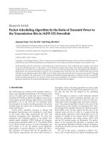
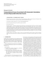
This two-layer structure, depicted in Figure 1, facilitates
the reuse of the control system thanks to the separation be-
tween data and their manipulation. When, for instance, the
plant is modified, it is sufficient to update the related portion
inside the model without manipulating the code. Then, the
designer is forced to manipulate models.
4.1. Production system model layer
Let us now describe in more detail the proposed architecture.
For the production system model, it is useful to notice that
it is possible to identify many common conceptual elements
in flexible manufacturing systems, in spite of their large va-
riety of types. The metamodeling techniques come to help
in modeling and designing of such common elements. In
this way, it possible to separate general rules to build models
(production system metamodel) from the model of a specific
application case (production system model, instantiation of
the production system metamodel) as shown in Figure 1.
The production system metamodel and model have typ-
ically a declarative nature, particularly useful for human ma-
nipulation. General criteria to find entities and relations put
into the metamodel pass through the analysis of the level
of configurability and reconfigurability of the set of the ad-
dressed manufacturing applications. Pabadis’Promise deals
Production
system
meta-model
Production
system
model
Role
meta-model
Role
model
Agent
meta-model
Agent
model
Instantiate
Instantiate
Instantiate
Production system model layer
Agent-based interpreter layer
Figure 1: Development process of the two-layer control architec-
ture.
with reconfigurable manufacturing systems which are manu-
facturing systems characterized by frequent changes of prod-
ucts and product recipes, plant components and layouts, pro-
duction mix, and production orders, thus allowing to react
more rapidly to market changes and needs. In addition, it fo-
cuses mainly on the design of the MES functionalities of the
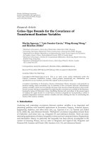
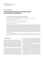
control system. For these reasons, the main entities, belong-
ing to the production system metamodel, are as follows.
P2Material: this entity corresponds to raw material or
lots of raw materials, material or lot of materials, consum-
able, energy, lubricants, and so on. P2Material has a self-
relation because it can belong to a material lot of the same
type and it is in relation with
(i) P2Resource: aP2materialisrequiredbyaP2Resource
inordertoprovideitsabilities;
(ii) P2Quantity: it describes the number of a given
P2Material (raw material lots or 2Product).
P2Product. It is a good, material, product (finished or
semifinished) or a service (nonmaterial product) which
is manufactured in a value-adding process described by
P2ProcessSegment. A P2Product can be used as a compo-
nent of another P2Product. It is the only entity that special-
izes P2Material entity.
P2Resource. It is a collection of persons or equipments re-
quired to execute an activity (i.e., a resource supports a spe-
cific activity). It can represent either a simple resource or a set
of resources with similar roles and properties. P2Resource is
specialized by P2Equipment. It has a self-relation because it
can be a composition of other P2Resource entities and it is in
relation with the following.
4 EURASIP Journal on Embedded Systems
P2manufacturingPlant
P2Ability
P2ProcessSegment
P2MachineP2Robot
P2Tool
P2Equipment
P2Resource
P2Quantity
P2Material
P2Product
Figure 2: Main entities and relations of the production system metamodel.
P2ManufacturingPlant: it describes the overall plant or
part of the plant (i.e., working cell). A P2Resource belongs
to a P2ManufacturingPlant.
P2Equipment: it defines sites, areas, production units,
production lines, work cells, process cells, units, machines,
tools, devices, or even software. P2Equipment is a durable
resource. It is specialized by P2Machine (it is a machine or a
working center), P2Robot, P2Tool, and it is in relation with
the following.
(i) P2Ability.Itdefineswhataresource(oracategoryof
resources) is able to do in order to support or to be
involved during a P2ProcessSegment.
(ii) P2ProcessSegment. In this case, it represents a mainte-
nance process required by a P2Equipment.
P2ProcessSegment. It represents a manufacturing process
or an activity which is part of a manufacturing process or
a maintenance process. If it represents an activity, the pro-
duction means the transformation (modification, moulding,
assembling, drilling, painting, etc.) and/or the transportation
and/or the controlling/verifying operation and/or the storage
of a (set of) input into a (set of) output. It is in relation with
P2Ability (because it requires ability in order to provide its
activities). P2ProcessSegment has relation with itself to mean
subactivity, alternative processes, and activities in sequence.
Entities and relations mentioned above are represented
in Figure 2.
More in general, the classes belonging to Pabadis’Promise
production system metamodel can be divided in three groups
[10]. The concepts related to human and physical resources,
such as working areas, machines and their abilities, devices,
tools, and organization units, are in one group. The second
group includes classes that express concepts of product, pro-
duction order, rough and semifinished materials, and their
quantities. Classes that express maintenance or process activ-
ities such as workings, transport, storing, control, and veri-
fication operations are in a third group. Other concepts that
describe events, parallelism, and synchronization among ac-
tivities are also in this group. Each class of the functional
metamodels has attributes, some of which are common to all
classes (e.g., name, description, identifier) and some others
are specific of a given class.
4.2. Agent-based interpreter layer
In the second layer, there are the control system functions,
which execute the production orders using only information
coming from the first level. It is implemented as a multiagent
system. Agents offer processing ability to implement all the
functions required to execute the production orders [11].
Nowadays, the systems managing the manufacturing
plants are organized in a hierarchy composed of the follow-
ing:
(i) enterprise resource planning (ERP) that provides
management services;
(ii) manufacturing execution system (MES) and supervi-
sory control and data acquisition (SCADA) that im-
plement production automation;
(iii) field control.
Luca Ferrarini et al. 5
Almost all the entities that belong to a multiagent control
system are in the MES layer placed between ERP and field
control layers.
Pabadis’Promise project has decided to use an agent ar-
chitecture because agents are autonomous components able
to react, pursue own goals, and communicate with each
other using a specific language, useful to express complex in-
teractions. Moreover, agents are software components, pro-
vided with internal function and basic routine (such as in-
teraction and communication protocols). They implement a
distributed system capable of getting flexibility required by
manufacturing companies.
One of the most successful methodologies to specify and
design multiagent system is GAIA [12],thatprovideseasy-
to-use tools, a semiformal methodology, and a system static
structure. GAIA is organized in two phases. The first one
is the analysis of the system described as a set of inter-
acting roles characterized by activities and protocols. Ac-
tivities are role internal actions, not dependant on other
roles that describe data processing and data transmission.
Protocols define the messages the roles can exchange. So,
in this phase, the mission assigned to the second level is
specified in the so-called role model, avoiding any indica-
tion about how to implement it. The second phase is the
specification of the agent system defining the agent types
and the relations between agents and the roles to be im-
plemented. An agent model is the outcome of this second
phase.
The Manufacturing Execution Systems Association
(MESA) has defined 12 main functionalities of automation.
Pabadis’Promise project has taken these functionalities into
consideration and selected those that are in scope and a role
was associated to each of them. The main roles, described by
Pabadis’Promise, are as follows.
(i) Resource manager: it is responsible for the overall
management of a resource. It will cover all types of
resources used within the P2 architecture including
manufacturing resources, human resources, transport
resources, material resources, and others.
(ii) Order manager: it is responsible for the execution con-
trol of an order and/or order parts. It will cover all
types of orders independent of its nature like man-
ufacturing orders, maintenance orders, and informa-
tion orders.
(iii) Ability broker: it is responsible for the collection, eval-
uation, and communication of all resource abilities.
(iv) Product data repository: it is responsible for the man-
agement of all product related data.
(v) Resource supervisor: it handles the integration of legacy
systems at field control and MES levels.
(vi) Order supervisor: it is responsible for the creation, ini-
tialization, and supervisory control of order managers.
It will receive information about order initialization
and order changes information from ERP and will
transform them into order manager information.
(vii) Enterprise resource planning: it is responsible for the
management of data related to orders and resources.
It handles the integration of the order-oriented parts
of ERP in the P2 architecture.
(viii) Information collector: it is a generic data sink respon-
sible for the collection of order and resource-related
data. It is one handle for the integration of parts of ex-
isting systems like ERP, SCADA, historians, and others.
Note that the metamodeling techniques can be used also to
define the second layer. In this way, it can be decomposed
into metamodel and model of the roles and metamodel and
model of agents. The role metamodel defines the types of
roles, activities, and protocols, in a very precise way. It cor-
responds to the role model defined by GAIA and its purpose
is to guide the use of all and only the concepts defined in the
role metamodel. The role model describes the second-layer
mission, which is related to a specific plant control. The role
model includes as many instances of resource manager as the
resources in the plant and as many instances of order man-
ager as the products to be produced.
In Pabadis’Promise, there is a one-to-one relation be-
tween agent types and role types. This choice is justified be-
cause each role has specific responsibilities completely differ-
ent from the responsibilities of other roles. Even if an agent
could instantiate more than one role, the one-to-one relation
between agent type and role type seems more correct and ef-
fective.
As for the production system metamodel, the role meta-
model has been conceived starting from the analysis of ex-
isting plants, and, in particular, of 2 generic manufactur-
ing scenarios: the manifold and the car production system.
Comunance and differences among these scenarios allowed
to develop generic concepts but sufficiently specific for the
considered domain. Therefore, the metamodels proposed by
Pabadis’Promise, and discussed here, are effective for the
given problem, but should not be considered as the optimal
and unique solution.
What is relevant in the approach we proposed is the
separation between a description of both plant resources—
providing services—and products—requiring services—,
and a generic unique executor able to read these data, to
find the match between supply and demand, and then to
control the production. The proposed control architecture
is thus characterized by a complete separation between sys-
tem data, and execution environment. The idea makes one
step forward the concept of framework [13], that is to pre-
serve as much as possible information from a plant to an-
other one. We do not develop only a framework (the pro-
duction system metamodel) but also a generic execution
engine (the agent metamodel) that can be used as it is
in different application cases. Such an approach hides the
programming problems (encapsulated in the generic agent-
based execution engine), leaving the control engineer ef-
fort focused on the product/plant description. This mod-
ularization strategy is then the key feature for the im-
provement of both reuse and reconfigurability of the con-
trol architecture. In particular, the isolation of data al-
lows the system to be easily and quickly reconfigured and
then able to react in short time to dynamic requirement
changes.
6 EURASIP Journal on Embedded Systems
4.3. Metamodels and metalevels for
production systems
Using modeling techniques, concept presentation can be or-
ganized in different abstraction levels, called metalevels that
are composed by metamodels or models. Each metalevel de-
pends on the content of previous level and defines rules to
create the subsequent level. The metamodel of the first met-
alevel (called OO metamodel) defines the object-oriented el-
ements such as classes, attributes, hierarchical links, or in-
heritance links between classes, cardinality relations, as well
as generic and direct links between classes. The immediate
following metalevel is composed only by instances of classes
and links defined in the OO metamodel. Clearly, other met-
alevels may be added. Each of them will contain instances of
the entities defined in the metamodel of the previous level. If
new concepts have to be introduced into a specific metalevel,
they must be defined in the previous metalevel. A model can
be considered in its turn as a metamodel if its instances can
be further instantiated. So, the last model, the one represent-
ing the specific application, belongs to the last metalevel.
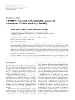
Given the above basic definitions, through metamodel-
ing techniques two ways are available to implement a spe-
cific model. In the first one, more intermediate metalevels
are introduced between the first metalevel (OO metamodel)
and the last metalevel (the model). In the second one, a
unique intermediate metalevel is used. In this metalevel, a
metamodel is implemented that can be “enriched” with new
classes of a more specific domain. In this way, a complete
metamodel, specific for that domain, is implemented.
As for the model instantiation (last metalevel), in the
multiple intermediate metalevel approach, only the classes
defined in the last metamodel can be instantiated in the
model. In the single intermediate metalevel approach, any
class defined in the unique intermediate metamodel can be
used.
Let us now analyze in more detail advantages and disad-
vantages of the two approaches.
In the first solution, each metalevel is only composed by
instances of classes defined in the previous metalevel. Notice
that the class instances are not objects, but classes that can be
further instantiated in the metalevels shown in Figure 3.
Example 1. In the first metalevel, class and class attribute
concepts are defined. In the second metalevel, class concept
can be instantiated in equipment class and its attributes are
defined, for example, they can have a name and a type. In
the third metalevel, equipment class can be instantiated in a
machine that has the attribute colour (name) with the field
type. In the fourth metalevel, a machine can be instantiated
in MyMachine and its colour attribute can be, for example,
red.
As said above, if in a given metalevel there is a need to
have a new concept, this concept has to be present in the pre-
vious metalevel. This means that, if a concept defined in the
first metalevel is needed in the third metalevel, then this con-
cept has to be also redefined in the second metalevel. This
operation may be difficult. For example, OO metamodel de-
fines generic relation among classes that can be instantiated
in a specific relation in the second metalevel. If the concept
of generic relation is also needed in the third metalevel, it is
indispensable to instantiate a new class called “generic rela-
tion” in the second metalevel. It is needed to define that the
new class has a source and a destination. Instancing this class,
the concept of generic resource is also available in the third
metalevel. This operation can be very complex and it is prone
to errors.
If more intermediate metalevels are needed, the passage
form a metalevel to another one means that the set of the
concept types defined in a given metalevel is smaller or equal
to the set of the concept type defined in the previous met-
alevel. In fact, it is only allowed to instantiate concepts of
the previous metalevel. This constrains modeling freedom to
the right amount permitted, thus fostering the proper use
of models without repetitions or inconsistencies. This also
means that the first metalevel must contain the possibility to
model all the next entities, which may be cumbersome.
On the contrary, in the single intermediate metalevel so-
lution, the unique intermediate metalevel is composed by
classes that have relations of specialization among them.
This offers advantages in manipulation. For example, if
there is a need to add new concepts (or to change previously
defined concepts) to instantiate in the final model, only one
metamodel must be modified. The disadvantage is that there
is no control on the changes in the model. Whereas, in a
structure composed of more than one metalevel, it is diffi-
cult to introduce changes because modifications may propa-
gate to more metalevels.
To build the production system model of an existing
plant in a systematic way, the following methodology of five
steps can be used:
(1) list all the plant physical components (including infor-
mation about the layout of the whole plant),
(2) define products,
(3) describe working operations,
(4) describe the main control strategies driving the plant,
(5) implement the plant model.
Let us now describe in more detail the above steps. In the
first step, it may be useful, when dealing with large plants,
to organize its components into hierarchical groups (e.g., a
plant composed of cells which in turn are composed of ma-
chining centers, which in turn are composed of tools, buffers,
etc.). A general criterion of aggregation is difficult to state,
but, for specific domains of manufacturing systems, some
suitable frameworks have already been proposed in litera-
ture [13, 14]. In the second step, types of products have to
be specified, along with their necessary rough or semifin-
ished material. In the third step, all the operations related
to products are described. Possible decomposition into sub-
operation rules can be applied and formal methods can be
used to model them (process algebras, automata, etc.). In the
fourth step, all the activities to be performed to accomplish
the tasks necessary to realize the manufacturing process are
represented using a diagram. Finally in the fifth step, it is de-
fined which functional metamodel class every system com-
ponent belongs to.
Luca Ferrarini et al. 7
First metalevel Second metalevel N th metalevel Last metalevel
First metalevel
Second metalevel
Last metalevel
MetamodelMetamodel Model
OO
metamodel
OO
metamodel
Instantiate
Instantiate
Instantiate
Instantiate
···
Complete metamodel
Production
system
model
Figure 3: Metalevels used for the production system description.
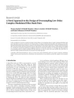
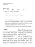
4.4. Application to a real test-case
As case study, a typical plant to produce car manifolds has
been chosen. This plant, sketched in Figure 4,
(i) produces parts that can require more than one work
(milling, boring, etc.),
(ii) works different types of manifolds,
(iii) has load/unload areas and central/local stores,
(iv) is organized in working cells.
In more detail, manifold plant has the following:
(i) 1 input/output area including 1 load/unload station, 1
central store for pieces, 1 central store for fixtures, and
1robot,
(ii) 4 identical machining cells including 2 machining cen-
ters, 1 local input/output area, 1 robot, 1 buffer, 1 local
store for pieces, and 1 local store for fixture,
(iii) 1 tool transport composed of a shuttle that connects
all machining cells.
A manifold is obtained by a rough material in aluminium.
The production of a generic manifold is obtained in two sep-
arated phases. An example of these two machining phases for
a given manifolds is as follows:
(1) milling 6 slots of cylinder with a diameter of 100 mm,
making 3 holes of reference, and milling 4 cylinders
with diameter 10 mm;
(2) milling carburettor plate, making a hole of carburettor
plate, and tapping holes of carburettor plate.
The manifold production system model is composed of as
many instances of P2Machine class as machines which are in
the plant. Each machine has abilities described by instances
of P2Ability class. In this case study, all machines are able to
make the first and the second working phases of the mani-
fold. Cell robots, represented by instances of P2Robot class,
are able to move pieces in the machining cell. Each man-
ifold is described by P2Product class and its rough mate-
rial is a P2Material. Workings are P2ProcessSegment. Each
P2ProcessSegment requires abilities in order to achieve its
objective. For example, to implement the first working phase,
a machine, able to make milling and holes with specific diam-
eters, is needed. P2ProcessSegment class can describe activity
at different levels of detail.
For simplicity, only two workings of the manifold are
considered, the first and the second phase, without further
details. If a plant component (or an ability or a working se-
quence) chances, it is enough to modify the part of the pro-
duction system model that describes that component.
In the agent model, there are as many resource agents
(RAs) as the plant resources, for example, each machining
center and each robot has an RA. Each RA takes information
about the resource to manage the production system model
and informs AB about resource abilities. There is a unique
resource agent supervisor (RAS) that manages all RAs.
When a new production has to start, ERP sends to order
agent supervisor (OAS) the request to produce manifolds.
OAS asks IC for the plant state. If the plant is available for
the new production, then OAS accepts the commission and
creates an order agent (OA). OA is responsible for the entire
production. If necessary, OA can create as many sub-OA as
manifolds to produce. Each sub-OA controls production of
one manifold. At the beginning, sub-OA asks PDR for infor-
mation about workings. PDR takes all the information about
production description from the production system model.
Then, sub-OA has to find the resource able to make the first
working, for example, the first phase. For this reason, sub-OA
contacts AB. AB compares the required ability with available
abilities and gives to sub-OA the result of the search. Sub-OA
contacts all the RAs that have the required ability and asks
them for a possible schedule. Then, sub-OA reserves the RA
that has the best schedule. In the same way, sub-OA searches
the RA of the second working phase.
In any time, if plant components (or the production)
change, the production system model can be modified. The
change is felt by the agents. In fact, if there are, for example,
8 EURASIP Journal on Embedded Systems
1 Load-unload fixtures station
2 Load-unload part baskets station
3 Part baskets main store
4 Fixtures main store
5 Transport robot from-to cell
6 Machining center (milling )
7 Part baskets local store
8Fixtureslocalstore
9Basketandfixturebuffer
10 Load-unload fixture place
11 Robot pliers local store
12 Overturners local store
13 Cell robot for transport
fixtures, baskets,
pliers, overturners
load-unload parts
Cell 1 Cell 2 Cell 3 Cell 4
11
8
13
10
7
9
12
6
2
1
3
4
5
Input/output
area
To o l t r a n s p o r t
Figure 4: Plant layout.
new manifold to produce, ERP informs OAS about the
change. In the same way, OAS contacts OA and sub-OA.
At the end of all workings, when all the manifolds are
produced, OAS informs ERP and waits for new commissions.
A full simulation model will be available for the end of
the Pabadis’Promise project (by the mid of 2008) to be used
in a mixed/virtual reality context. Such a simulation model,
implemented using the Visual Components 3D toolkit [15],
will be controlled by the multiagent system (real control sys-
tem) through suitable control device interfaces. The pur-
pose of such a simulation environment is to validate the pro-
posed control architecture, that is, to evaluate quantitatively
its adaptability to late and unpredictable changes, which are
related to production order, machine breakdowns, resource
ability modifications, reconfigurations, and so on.
5. SUMMARY AND OUTLOOK
In the paper, the concept of metamodeling techniques and
their usage in the development of reconfigurable manufac-
turing systems is addressed. In particular, it shows the ad-
vantages of such techniques in the construction of domain
specific abstraction mechanisms, such as the specification of
a product and production process description language for
manufacturing systems. The paper presents also how to use
this concept in a distributed agent-based control architecture
through the help of a test case represented by a real manufac-
turing plant producing manifolds. These topics are also ad-
dressed in the Pabadis’Promise European project where they
will be further investigated.
Through an extensive explanation and exemplification,
it is shown that the reconfigurability of control applications
can be achieved with
(i) early adoption of models (reuse of code through the
reuse of models),
(ii) separation of model specification from model inter-
pretation (two-layered architecture),
(iii) separation of model construction rules from actual
models (metamodeling techniques),
(iv) adoption of distributed and decentralized control ar-
chitecture (agent-based control),
(v) separation of code functions from models (role meta-
model and model).
Future works include the definition of a more formal
methodology to develop specific plant model, the develop-
ment of tools supporting the configuration phase of the
model, the study of how to model the scheduling algorithms
and how to introduce the behavior analysis capability within
the model.
REFERENCES
[1] M. G. Mehrabi, A. G. Ulsoy, and Y. Koren, “Reconfigurable
manufacturing system and their enabling technologies,” In-
ternat ional Journal of Manufacturing Technology and Manage-
ment, vol. 1, no. 1, pp. 113–130, 2000.
[2] M. Fowler, “Language Workbenches: The Killer-App for Do-
main Specific Languages?” www.martinfowler.com/articles/
languageWorkbench.html, 2005.
Luca Ferrarini et al. 9
[3] A. van Deursen, P. Klint, and J. Visser, “Domain-specific
languages: an annotated bibliography,” http://homepages.
cwi.nl/
∼arie/papers/dslbib, 2000.
[4] S. Kelly, “Improving Developer Productivity With Domain-
Specific Modeling Languages,” www.developerdotstar.com/
mag/articles/domain
modeling language.html, 2005.
[5] L. Ferrarini, C. Veber, F. Ferrari, and G. Fogliazza, “Applied
meta-modelling to convert IEC61499 applications into step7
environment,” in Proceedings of the European Control Confer-
ence (ECC’07), Kos, Greece, July 2007.
[6] T. Clark, A. Evans, P. Sammut, and J. Willans, “Applied Meta-
modelling: A Foundation for Language Driven Development,”
www.xactium.com, 2004.
[7] Object Management Group, OMG, www.omg.org, 2004.
[8] L. Ferrarini, C. Veber, A. L
¨
uder, et al., “Control architec-
ture for reconfigurable manufacturing systems: the PABADIS’
PROMISE approach,” in Proceedings of the 11th IEEE Interna-
tional Conference on Emerging Technologies and Factory Au-
tomation (ETFA ’06), pp. 545–552, Prague, Czech Republic,
September 2006.
[9] Pabadis Promise, FP6-IST-016649, PABADIS based Product
Oriented Manufacturing Systems for Re-Configurable Enter-
prises, www.pabadis-promise.org, 2005.
[10] Pabadis Promise Consortium, Deliverable 3.1—Development
of Manufacturing Ontology. Pabadis Promise, 2006.
[11] Pabadis Promise Consortium, Deliverable 2.1—Concept
of Overall PABADIS PROMISE Architecture Components.
Pabadis Promise, 2006.
[12] M. Wooldridge, N. R. Jennings, and D. Kinny, “The Gaia
methodology for agent-oriented analysis and design,” Au-
tonomous Agents and Multi-Agent Systems,vol.3,no.3,pp.
285–312, 2000.
[13] L. Ferrarini and G. Fogliazza, “Advanced control system de-
sign for machining centers,” in Proceedings of the IEEE/ASME
International Conference on Advanced Intelligent Mechatronics
(AIM ’01), vol. 1, pp. 671–676, Como, Italy, July 2001.
[14] L. Ferrarini, C. Veber, and G. Fogliazza, “Modelling, de-
sign and implementation of machining centers control func-
tions with object-oriented techniques,” in Proceedings of the
IEEE/ASME International Conference on Advanced Intelligent
Mechatronics (AIM ’03), vol. 2, pp. 1037–1042, Kobe, Japan,
July 2003.
[15] Visual Components, www.visualcomponents.com/, 2007.
[16] XMF-Mosaic XOCL, XMAP, XTOOL tutorials.