Báo cáo hóa học: "Research Article Binaural Rendering in MPEG Surround" doc
Bạn đang xem bản rút gọn của tài liệu. Xem và tải ngay bản đầy đủ của tài liệu tại đây (859.85 KB, 14 trang )
Hindawi Publishing Corporation
EURASIP Journal on Advances in Signal Processing
Volume 2008, Article ID 732895, 14 pages
doi:10.1155/2008/732895
Research Article
Binaural Rendering in MPEG Surround
Jeroen Breebaart,
1
Lars Villemoes,
2
and Kristofer Kj
¨
orling
2
1
Philips Research, HTC 34, 5656 AE Eindhoven, The Netherlands
2
Dolby Sweden AB, G
¨
avlegatan 12A, 11330 Stockholm, Sweden
Correspondence should be addressed to Jeroen Breebaart,
Received 29 June 2007; Revised 12 November 2007; Accepted 21 December 2007
Recommended by Antonio Ortega
This paper describes novel methods for evoking a multichannel audio experience over stereo headphones. In contrast to the
conventional convolution-based approach where, for example, five input channels are filtered using ten head-related transfer
functions, the current approach is based on a parametric representation of the multichannel signal, along with either a parametric
representation of the head-related transfer functions or a reduced set of head-related transfer functions. An audio scene with
multiple virtual sound sources is represented by a mono or a stereo downmix signal of all sound source signals, accompanied
by certain statistical (spatial) properties. These statistical properties of the sound sources are either combined with statistical
properties of head-related transfer functions to estimate “binaural parameters” that represent the perceptually relevant aspects
of the auditory scene or used to create a limited set of combined head-related transfer functions that can be applied directly on
the downmix signal. Subsequently, a binaural rendering stage reinstates the statistical properties of the sound sources by applying
the estimated binaural parameters or the reduced set of combined head-related transfer functions directly on the downmix. If
combined with parametric multichannel audio coders such as MPEG Surround, the proposed methods are advantageous over
conventional methods in terms of perceived quality and computational complexity.
Copyright © 2008 Jeroen Breebaart et al. This is an open access article distributed under the Creative Commons Attribution
License, which permits unrestricted use, distribution, and reproduction in any medium, provided the original work is properly
cited.
1. INTRODUCTION
The synthesis of virtual auditory scenes has been an ongoing
research topic for many years [1–5]. The aim of so-called
binaural rendering systems is to evoke the illusion of one
or more sound sources positioned around the listener using
stereo headphones. The positions of the sound sources can
preferably be modified in terms of the perceived azimuth,
elevation, and distance. More advanced systems also include
room acoustic models to simulate the acoustical properties
such as reflecting walls within the virtual space.
Binaural rendering has benefits in the field of research,
simulation, and entertainment [6]. Especially in the field of
entertainment, the virtual auditory scene should sound very
compelling and “real.” In order to achieve such a realistic
percept, several aspects have to be taken into account, such
as the change in sound source positions with respect to
head movement [7], room acoustic properties such as early
reflections and late reverberation [8], and using system
personalization to match the anthropometric properties of
the individual user [9–11]. Because of the complex nature
of current state-of-the-art systems, several concessions are
required for feasible implementations (cf. [12]), especially
if the number of sound sources that has to be rendered
simultaneously is large.
Recent trends in consumer audio show a shift from stereo
to multichannel audio content as well as a shift from immo-
bile to mobile devices. These developments cause additional
constraints on transmission and rendering systems. Firstly,
the number of audio channels that has to be transmitted
increases significantly (e.g., from two to six). The corre-
sponding increase in transmission bandwidth for conven-
tional, discrete-channel audio coders is often undesirable and
sometimes even unavailable. Secondly, consumers often use
headphones for audio rendering on a mobile device. To expe-
rience the benefit of multichannel audio, a dedicated binau-
ral rendering system is required. This can be quite a challenge
given the limited processing power and battery life of mobile
devices.
In this paper, two novel binaural rendering processes
will be described, which exploit recent advances in paramet-
ric multichannel audio compression. Both methods operate
2 EURASIP Journal on Advances in Signal Processing
on a parametric representation of a multichannel original
signal and a corresponding downmix signal, as is defined
by the recently finalized MPEG Surround standard [13]for
multichannel audio compression. An outline of the basic
principle of MPEG Surround is given in Section 2. The first
method, referred to as “parametric approach,” is based on
the analysis and synthesis of perceptually relevant attributes
“binaural parameters” of a virtual auditory scene. This
method is especially suitable for low-complexity simulation
of anechoic situations (possibly extended with parametric
methods for room acoustics simulation). The analysis and
synthesis of binaural parameters is outlined in Sections
3.2 and 3.3, and the integration of this method into
MPEG Surround is described in Section 5. The second
method is based on convolution-based synthesis that can
be applied directly on the downmix signal, without the
need of independent channel signals (as in conventional
methods). This method, which is referred to as a “morphed-
filter” approach, will be outlined in Section 4. It is especially
suitable to simulate echoic virtual environments and/or if
the parametric approximation of binaural parameters is not
sufficiently accurate. Finally, the two different methods are
evaluated in the context of MPEG Surround by means of
listening tests.
2. MPEG SURROUND
MPEG Surround [13–17]isanovelparametricmethodfor
efficient transmission of multichannel audio. In this audio
coding format, a multichannel audio signal is represented
as a downmix signal (typically mono or stereo) and a set
of “spatial parameters” that, among other aspects, describe
the statistical relations of the original multichannel signals
in terms of (relative) signal powers and correlation coeffi-
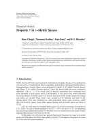
cients. The processing flow of MPEG Surround is visualized
in Figure 1. An MPEG Surround encoder (left panel of
Figure 1) generates a mono or stereo downmix from a
multichannel input signal and accompanying spatial param-
eters. These parameters are extracted for individual time/
frequency tiles of the input signals. The bandwidth of each
tile is approximately equal to one critical band, and the
duration is in the order of tens of milliseconds. The downmix
can be encoded using existing compression methods (legacy
coders). A multiplexer combines the resulting downmix
bit stream with the parameter bit stream to form an
output bit stream. The decoder, shown in the right panel
of Figure 1, performs the inverse process to generate the
multichannel output signals. The coding efficiency provided
by the parametric approach to represent spatial attributes is
quite significant; a parameter bit rate of about 6 to 12 kbps
(in addition to the bit rate required for the mono or stereo
coder) suffices to achieve high-quality multichannel audio
[16–18].
The MPEG Surround coder operates in a hybrid quadra-
ture mirror filter (QMF) bank domain [19]toenable
independent processing of individual time/frequency tiles.
The spatial parameter extraction process (at the encoder
side) and the spatial synthesis process (at the decoder side)
are all performed in this filterbank domain. The spatial
encoding process is provided by so-called two-to-One (TTO)
and three-to-two (TTT) encoding blocks, as outlined in
Figure 2. The first type, which is essentially similar to a
“parametric stereo” coder [19–24] encodes a stereo signal by
means of a mono signal, a channel level difference (CLD)
and an interchannel cross-correlation (ICC) parameter. The
second type (TTT block) represents three input signals
(typically, a left, right and center signal) as a stereo downmix
accompanied by two channel prediction coefficients (CPCs)
that enable decoder-side prediction of a third signal from
the two downmix channels. A possible prediction loss may
be compensated for by transmission of an additional ICC
parameter (see [14, 16, 17, 25] for more details).
Several TTO and TTT encoding blocks (E
i
)canbecon-
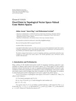
nected to create a certain tree configuration. Two examples of
such tree configurations are shown in Figure 2. The left panel
of Figure 2 shows a combination of 5 TTO encoding blocks
to represent a 6-channel input (l
f
, r
f
, c, l
s
, r
s
, and LFE for the
left front, right front, center, left surround, right surround,
and low frequency effects channel, resp.) as a mono signal x
accompanied by spatial parameters (P
i
).Atreeconfiguration
for stereo output, involving 3 TTO encoding blocks and one
TTT encoding block, is shown in the right panel, resulting in
a stereo downmix pair x
l
, x
r
.
3. BINAURAL PARAMETER ANALYSIS AND SYNTHESIS
3.1. Background
There is evidence that spatial parameters such as employed
in MPEG Surround and related spatial coding approaches
(see [14, 20, 26, 27]) can also be employed to describe
so-called head-related transfer functions (HRTFs) that are
used for binaural synthesis. Sound-source localization in the
horizontal plane is facilitated by interaural time differences
(ITDs) and interaural level differences (ILDs) [5, 28, 29],
caused by the relative path lengths and acoustic shadow effect
of the head. The properties of sound propagation also result
in an intricate frequency dependence of these cues. Sound
source elevation is predominantly facilitated by elevation-
dependent spectral peaks and notches that are superimposed
on the original sound source spectrum [11]. The perceived
distance of a sound source is based on the overall signal level,
the ratio of direct and reverberant sound, and spectral cues
[1, 2, 30, 31].
All acoustical cues that determine the perceived position
of the sound source are captured by a pair of HRTFs. The
corresponding time-domain impulse responses are denoted
HRIRs (head-related impulse responses). If individualized
HRTFs are used to simulate a virtual sound source, subjects
are not able to discriminate between real and virtual sound
sources [28, 32, 33]. This result indicates that HRTFs
indeed supply sufficient information for adequate binaural
rendering. However, several investigations have shown that
HRTFs may comprise pronounced properties in the signal
domain that seem perceptually irrelevant. For example, it has
been shown that for low frequencies, ITDs dominate sound
source localization, while at high frequencies, ILDs and
spectral cues (peaks and troughs resulting from reflections
JeroenBreebaartetal. 3
Multi-channel input
Encoder
Spatial parameter bit stream
MPEG
Surround
encoder
Legacy
down
mix
encoder
Multi
plexer
(a)
Demulti
plexer
Legacy
down
mix
decoder
MPEG
Surround
decoder
Spatial parameter bit stream
Decoder
Multi-channel output
(b)
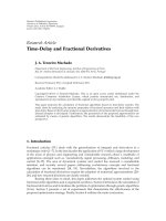
Figure 1: Concept of MPEG Surround. A multichannel audio signal is represented as a downmix signal and accompanying spatial parameters
(MPEG Surround encoder). The downmix can be encoded using an existing (legacy) compression method. The decoder separates the spatial
parameters from the core coder bitstream (demultiplexer), decodes the downmix, and reconstructs multichannel audio by reinstating the
spatial properties (MPEG Surround decoder).
l
f
r
f
c
LFE
l
s
r
s
E
3
(TTO)
E
4
(TTO)
E
2
(TTO)
P
3
P
4
P
2
E
1
(TTO)
P
1
E
0
(TTO)
P
0
x
(a)
l
f
l
s
r
f
r
s
c
LFE
E
0
(TTO)
E
1
(TTO)
E
2
(TTO)
s
l
P
0
s
r
P
1
s
c
P
2
E
3
(TTT)
P
3
x
r
x
l
(b)
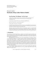
Figure 2: Two encoder tree configurations for 6-channel input and a mono downmix (left panel) or a stereo downmix (right panel). Each
block (E
i
) represents a TTO or TTT encoding block and generates a set of parameters (P
i
).
of shoulders and the pinnae) are more important [34].
Other researchers have successfully demonstrated that the
frequency-dependent ITD can be replaced by a constant,
position-dependent ITD without perceptual consequences
[14, 32, 35, 36]. A related finding is that the interaural
time difference can be replaced by a constant interaural
phase difference (IPD) within various frequency bands. The
resulting piecewise constant-phase curve does not result in
audible differences provided that the frequency bands are not
broader than critical bands [14].
There is also considerable evidence that certain details
of the HRTF magnitude spectra are irrelevant [37–39].
Specifically, it seems that constant spectral cues within critical
bands (or frequency bands that follow the ERB scale [40]) are
asufficient requirement for high-quality binaural rendering
[14, 38].
Given the commonalities between the parametric ap-
proach for audio compression and a parametric approach
to describe HRTFs, these can be efficiently combined in a
single binaural rendering application. In such a combined
approach, the so-called “binaural parameters” are estimated
representing simultaneous playback of all audio channels
over a virtual standard loudspeaker setup [41]. The inter-
relations between the virtual loudspeaker signals are given
by spatial parameters, while the relations between a virtual
loudspeaker and the resulting ear-drum signals are described
by HRTF parameters. The binaural parameter estimation
process is outlined in the next section.
3.2. Binaural parameter analysis
In conventional binaural rendering systems, a sound source
i with associated discrete-sampled time-domain signal z
i
is
rendered at a certain position by convolving the signal with
a pair of head-related impulse responses h
L,i
, h
R,i
, for the left
and right ears, respectively, to result in binaural signals y
L,i
,
y
R,i
:
y
m,i
= z
i
∗h
m,i
,(1)
with m
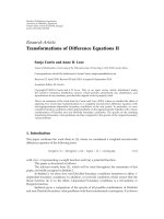
∈{L, R}. This process is visualized in the left panel
of Figure 3.
Expressed in a (complex-valued) subband domain with
time-index k and frequency band index b, the power of signal
y
m,i
(k,b) within a certain analysis frame k = 0, , K − 1is
given by
σ
2
y
m,i
(b) =
1
K
k
y
m,i
(k,b)y
∗
m,i
(k,b), (2)
with (
∗) the complex conjugation operator. If the HRTF
magnitude spectra are locally stationary (i.e., constant within
the frequency band b), this can be simplified to
σ
2
y
m,i
(b) = σ
2
h
m,i
(b)σ
2
z
i
(b), (3)
with σ
2
h
m,i
(b) the power within parameter band b of HRIR h
m,i
and σ
2
z
i
(b) the power of the source signal z
i
in parameter band
b within the current analysis frame.
4 EURASIP Journal on Advances in Signal Processing
Thus given the local stationarity constraint, the power
in a certain parameter band b at the level of the ear drums
follows from a simple multiplication of the power of the
sound source and the power of the HRTF in corresponding
parameter bands. In other words, statistical properties of
binaural signals can be deducted from statistical properties
of the source signal and from the HRTFs. This parameter-
based approach is visualized in the right panel of Figure 3.
Similar derivations lead to estimates of the interaural-phase
difference (IPD) between the signals y
L,i
and y
R,i
:
IPD(b)
= ∠
k
y
L,i
(k,b)y
∗
R,i
(k,b)
. (4)
Under the assumption of local stationarity of interaural
HRTF phase spectra, the IPD can be derived directly from the
HRTF spectra themselves, without involvement of the sound
source signal:
IPD(b)
= φ
i
(b), (5)
with φ
i
(b) the average interaural-phase difference of the
HRTF pair corresponding to position i and parameter band
b:
φ
i
(b) = ∠
k
h
L,i
(k,b)h
∗
R,i
(k,b)
. (6)
The equations above assume local stationarity of HRTF
magnitude and interaural phase difference spectra to esti-
mate the resulting binaural parameters. This stationarity
constraint has been shown to result in correct sound-source
localization properties [14]. However, strong deviations from
stationarity within analysis bands result in a decrease in the
interaural coherence (IC) for certain frequency bands, since
the relation between the two HRTF spectra within the band
of interest cannot be accurately described by a single phase
and level difference. Such decrease in the IC is perceived as
a change in the spatial “compactness” [2]. To capture this
property, the IC is estimated for each parameter band b.In
our context, the coherence is defined as the absolute value of
the average normalized cross-spectrum:
IC(b)
=
k
y
L,i
(k,b)y
∗
R,i
(k,b)
Kσ
y
L,i
(b)σ
y
R,i
(b)
. (7)
The IC parameter has a dependency on the source signal z
i
.
The expected value is given by
IC(b)
= ρ
i
(b), (8)
with
ρ
i
(b) =
|
k
h
L,i
(k,b)h
∗
R,i
(k,b)|
Kσ
h
L,i
(b)σ
h
R,i
(b)
. (9)
In summary, under the local stationarity constraint, the
binaural parameters σ
y
L
, σ
y
R
, IPD, and IC resulting from a
single sound source can be estimated from the sound-source
parameters σ
z
i
and the HRTF parameters σ
h
L,i
, σ
h
R,i
, φ
i
,andρ
i
.
For multiple simultaneous sound sources, conventional
systems convolve each individual source signal i with an
HRTF pair corresponding to the desired position, followed
by summation:
y
m
=
i
z
i
∗h
m,i
. (10)
The binaural parameters σ
y
L
, σ
y
R
, IPD, and IC between
signals y
L
, y
R
resulting from the ensemble of simultaneous
sound sources z
i
can be estimated in a very similar way as
described above, based on the sound source parameters σ
z
i
and their mutual normalized correlation coefficients c
i
1
,i
2
on
the one hand, and the HRTF parameters σ
h
L,i
, σ
h
R,i
, φ
i
,andρ
i
on the other hand:
σ
2
y
m
=
i
σ
2
h
m,i
σ
2
z
i
+
i
1
i
2
/
=i
1
r
m,i
1
i
2
c
i
1
,i
2
cos
φ
i
1
−φ
i
2
2
,
(11)
with
r
m,i
1
i
2
= σ
2
h
m,i
1
σ
2
h
m,i
2
σ
2
z
i
1
σ
2
z
i
2
ρ
i
1
ρ
i
2
. (12)
In a similar way, the IPD and IC are given by
IPD
= ∠(χ), IC =
|
χ|
σ
y
L
σ
y
R
,
(13)
with
χ
=
i
e
jφ
i
ρ
i
σ
2
z
i
σ
h
L,i
σ
h
R,i
+
i
1
i
2
/
=i
1
e
(jφ
i
1
+jφ
i
2
)/2
c
i
1
,i
2
q
i
1
i
2
,
(14)
with
q
i
1
i
2
= σ
2
h
L,i
1
σ
2
h
R,i
2
σ
2
z
i
1
σ
2
z
i
2
ρ
i
1
ρ
i
2
. (15)
In the equations above, the subband index (b)isomitted
for clarity. The reader is referred to [14] for a more detailed
derivation of σ
y
L
, σ
y
R
,IPD,andIC.
3.3. Binaural parameter synthesis
3.3.1. Synthesis from mono downmix
In the case of an MPEG-Surround encoded signal with a
mono downmix, the synthesis process comprises reinstating
the binaural parameters on the mono downmix signal x of
the object signals. Assuming incoherent source signals z
i
, the
downmix is given by
x
=
i
z
i
. (16)
In the case of (partially) correlated source signals (i.e., the
pairwise correlation coefficient c
i
1
,i
2
is nonzero for certain
signal pairs), the downmix is preferably scaled in each
frequency band and for each frame independently to ensure
energy preservation (cf. [14, 16]). As a result, the power σ
2
x
in
JeroenBreebaartetal. 5
Source signal
z
i
Binaural signals
y
L,i
h
L,i
HRIRs
h
R,l
y
R,i
(a)
Binaural parameters
Source parameters
σ
z
i
HRTF parameters
σ
h
L,i
ρ
h
L,i
h
R,i
σ
h
R,i
σ
y
L,i
σ
y
R,i
IPD, IC
(b)
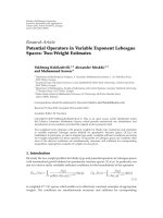
Figure 3: Synthesis of a virtual sound source by means of HRIR convolution (left panel) and by means of parametric representations (right
panel).
each parameter band b of a downmix signal frame k is then
given by
σ
2
x
=
i
σ
2
z
i
. (17)
The required binaural parameters are derived from
HRTF parameters (σ
h
L,i
, σ
h
R,i
, φ
i
, ρ
i
) and signal parameters
(σ
z
i
, c
i
1
,i
2
) as described in Section 3.2. The signal parameters
σ
z
i
and c
i
1
,i
2
are assumed to be available as side information
accompanying the down-mix x. In the case of MPEG
Surround, the statistical properties of the input signals
are described as pairwise level differences (CLDs) and
correlations (ICCs) in a tree structure (cf. Figure 2,left
panel), which need to be converted to relations between the
original input channels. The CLD
i
(b) is defined as the power
ratio of the two input signals (q
1
, q
2
) in parameter band b of
the encoding block TTO
i
:
CLD
i
(b) =
σ
2
q
1
(b)
σ
2
q
2
(b)
. (18)
Given the tree structure shown in the left panel of Figure 2,
the powers of the input signals z
l
f
, z
l
s
, z
r
f
, z
r
s
, z
c
are derived
from the CLDs by combining the individual energy ratios of
each TTO element:
σ
2
z
l
f
(b) =
CLD
0
(b)
1+CLD
0
(b)
CLD
1
(b)
1+CLD
1
(b)
CLD
3
(b)
1+CLD
3
(b)
,
σ
2
z
r
f
(b) =
CLD
0
(b)
1+CLD
0
(b)
CLD
1
(b)
1+CLD
1
(b)
1
1+CLD
3
(b)
,
σ
2
z
c
(b) =
CLD
0
(b)
1+CLD
0
(b)
1
1+CLD
1
(b)
,
σ
2
z
l
s
(b) =
1
1+CLD
0
(b)
CLD
2
(b)
1+CLD
2
(b)
,
σ
2
z
r
s
(b) =
1
1+CLD
0
(b)
1
1+CLD
2
(b)
.
(19)
In the equations above, the LFE signal is assumed to be
merged with the center speaker as one single signal, and
hence the parameters of OTT
4
are absent in the equations
above.
The ICC
i
(b) is defined as the normalized cross-corre-
lation coefficient of the two input signals of TTO
i
.Ascanbe
observed from Figure 2, four ICC parameters (i.e., exclud-
ing TTO
4
) are available to represent 10 unique pairwise
correlation coefficients c
i
1
,i
2
of 5 input channels. This ill-
defined problem is solved by a heuristic rule that all pairwise
correlations are set to zero, except for
c
l
f
,r
f
= ICC
3
, c
l
s
,r
s
= ICC
2
.
(20)
The reconstructed binaural signals
y
L
, y
R
can be obtained
using a matrix operation M(b) that is derived for each
parameter band (b):
⎡
⎣
y
L
(k,b)
y
R
(k,b)
⎤
⎦
=
M(b)
⎡
⎣
x(k, b)
D(x(k, b))
⎤
⎦
, (21)
with D(
·) a so-called “decorrelator” which generates a signal
that has virtually the same temporal and spectral envelopes
as its input but is independent from its input. This method
of binaural synthesis is identical to the parameter synthesis
method applied in “parametric stereo” decoders [20]. The
matrix coefficients ensure that for each frame, the two
binaural output signals
y
L
, y
R
have the desired levels, IPD
and IC relations. A suitable solution for the synthesis matrix
M(b)isgivenby(see[20] for details)
M(b)
=
⎡
⎣
λ
L
(b)cos
α(b)+β(b)
λ
L
(b)sin
α(b)+β(b)
λ
R
(b)cos
−
α(b)+β(b)) λ
R
(b)sin
−
α(b)+β(b)
⎤
⎦
,
(22)
with λ
L
(b), λ
R
(b) two scale factors that determine the
(complex) gain between the downmix signal and the left and
right binaural output signals, respectively:
λ
L
(b) =
σ
y
L
(b)
σ
x
(b)
e
+jIPD(b)/2
, λ
R
(b) =
σ
y
R
(b)
σ
x
(b)
e
−jIPD(b)/2
.
(23)
6 EURASIP Journal on Advances in Signal Processing
The angle α(b) determines the coherence between y
L
, y
R
according to
α(b)
=
1
2
arccos
IC(b)
, (24)
while the angle β(b) minimizes the decorrelator output
signal:
β(b)
= tan
σ
y
R
(b) −σ
y
L
(b)
σ
y
R
(b)+σ
y
L
(b)
arctan
α(b)
. (25)
3.3.2. Extension to stereo downmixes
In the previous sections, binaural parameters were analyzed
and reinstated from a mono downmix signal x. For several
applications, however, it is beneficial to provide means to
extend the downmix channel configuration to stereo. An
example of a relevant application scenario is the synthesis
of a virtual multichannel “home cinema setup” using a
stereo downmix signal pair x
L
, x
R
accompanied by spatial
parameters. This process will be discussed in the context of
the MPEG Surround tree structure shown in the right panel
of Figure 2. In the 3 TTO encoding blocks, input signals are
pairwise combined to result in three intermediate signals s
L
,
s
R
,ands
C
. These intermediate signals are then combined
into a stereo downmix pair x
L
, x
R
by a TTT encoding block
according to
⎡
⎣
x
L
x
R
⎤
⎦
=
⎡
⎢
⎢
⎢
⎣
10
1
2
√
2
01
1
2
√
2
⎤
⎥
⎥
⎥
⎦
⎡
⎢
⎢
⎢
⎣
s
L
s
R
s
C
⎤
⎥
⎥
⎥
⎦
. (26)
TheextractedCPCparametersenablereconstructionofthe
intermediate signals
s
L
, s
R
,ands
C
at the MPEG Surround
decoder side (using a corresponding decoder block indicated
by TTT
−1
) according to
⎡
⎢
⎢
⎢
⎣
s
L
(k,b)
s
R
(k,b)
s
C
(k,b)
⎤
⎥
⎥
⎥
⎦
=
M
−1
TTT
(b)
⎡
⎣
x
L
(k,b)
x
R
(k,b)
⎤
⎦
, (27)
with an upmix matrix M
−1
TTT
(b)foreachparameterband
depending on the CPC parameters (see [16]formore
details).
For each of the three reconstructed intermediate signals
s
L
, s
R
,ands
C
, an individual 2 × 2 upmix matrix W(b)
is computed for those virtual sources that are present in
that particular downmix signal. In other words, one matrix
W
s
L
(b) is estimated to reinstate the binaural parameters
resulting from channels l
f
and l
s
, one matrix W
s
R
(b)to
reinstate binaural parameters resulting from r
f
and r
s
,
and one matrix to reinstate the binaural parameters from
channel c, assuming that the content of the LFE channel
is also reproduced by the center channel (i.e., CLD
2
=
∞
).Therequiredchannelpowersσ
z
are derived from the
MPEG Surround OTT parameters (right panel of Figure 2)
according to
σ
2
l
f
=
CLD
0
1+CLD
0
,
σ
2
l
s
=
1
1+CLD
0
,
σ
2
r
f
=
CLD
1
1+CLD
1
,
σ
2
r
s
=
1
1+CLD
1
.
(28)
Furthermore, the channel correlation coefficients are
assumedtobezero(i.e.,c
i
1
,i
2
= 0, for i
1
/
=i
2
). The derivation
of the matrix elements is equal to the method described in
Section 3.3.1, with the exception that the coherence (IC) for
each individual matrix is assumed to amount to +1. This
assumption is based on the observation that the coherence
of these matrices predominantly represents coherence in a
front/back direction, which is assumed to be a less salient cue
than coherence in a left/right direction. Given a coherence
value of +1, no decorrelator signal is required in the synthesis
and hence each individual matrix simplifies to
W
s
(b) =
⎡
⎣
λ
L,s
(b)0
λ
R,s
(b)0
⎤
⎦
. (29)
Subsequently, the individual outputs of each 2
× 2matrix
operating on one intermediate signal are simply summed to
result in the binaural output pair
y
L
, y
R
:
⎡
⎣
y
L
(k,b)
y
R
(k,b)
⎤
⎦
=
W
s
L
(b)
⎡
⎣
s
L
(k,b)
0
⎤
⎦
+ W
s
R
(b)
⎡
⎣
s
R
(k,b)
0
⎤
⎦
+ W
s
C
(b)
⎡
⎣
s
C
(k,b)
0
⎤
⎦
.
(30)
Given the fact that the intermediate signals
s
L
, s
R
,and
s
C
follow from the downmix pair x
L
, x
R
given a matrix
operation M
−1
TTT
(b) according to (27), the complete binaural
rendering process can be written as a single, 2
× 2matrix
operation M(b)foreachparameterbandb:
⎡
⎣
y
L
(k,b)
y
R
(k,b)
⎤
⎦
=
M(b)
⎡
⎣
x
L
(k,b)
x
R
(k,b)
⎤
⎦
. (31)
4. MORPHED-FILTER APPROACH
4.1. Introduction
The parametric approach outlined in the previous section
employs a lossy representation of HRTFs (using only spectral
envelopes, average-phase differences, and coherences). In
the case of echoic impulse responses (so-called binaural
room impulse responses (BRIRs), or binaural room transfer
JeroenBreebaartetal. 7
functions (BRTFs)), the parametric approach is not capable
of accurate modeling of all relevant perceptual aspects. In this
case, a less compact HRTF or BRTF representation can be
obtained by extending the 2
×2 processing matrix in the time
domain (i.e., having multiple “taps”). This extension is only
defined for a stereo downmix and will be outlined below.
The basic principle is to combine the original set of
HRTFs or BRTFs into a limited set of four impulse responses
that can be directly applied on the stereo downmix. This is
feasible when a representation of the original multichannel
signal is available, which relies on stereo downmix and a set
of spatial parameters, as is the case for MPEG Surround. The
proposed method is beneficial since it only operates on four
filters as opposed to ten filters normally used for binaural
rendering of a five channel signal, and furthermore, it enables
the use of echoic impulse responses (BRIRs). A design goal
of the method is to maintain a waveform match with the
conventional reference binaural signal (32)insituations
where the MPEG Surround multichannel signal obtains a
waveform match with the original multichannel signal. For
a mono downmix this only happens for single loudspeaker
sources, but for a stereo downmix the MPEG Surround
decoding system enables waveform reconstruction for many
two-loudspeaker combinations. The term “morphed-filter”
approach refers to a dynamic combination of the front/back
contributions which can be thought of as the creation of a
virtual loudspeaker that for each time-frequency tile replaces
a front/back loudspeaker pair. The corresonding HRTF
data is interpolated in phase and amplitude with weights
depending on the parametric surround side information.
4.2. Subband filter representations
The signal modifications of MPEG surround are performed
in the domain of a complex modulated filter bank which
is not critically sampled; see [19]. Its particular design
allows for a given time-domain filter to be implemented at
high precision by filtering each subband signal in the time
direction with a separate filter. The resulting overall SNR
for the filter implementation is in the 50 dB range with the
aliasing part of the error significantly smaller. Moreover,
these subband domain filters can be derived directly from the
given time-domain filter. The filter conversion is specified in
[13] and the details of its derivation can be found in [42].
We will consider a single fixed subband of the QMF
filterbank and omit any subband indexing for clarity. The
frequency resolution of the spatial parameters is adapted to
this filterbank in the sense that there is only one parameter
per subband. The reference output of the filtering approach
is the superposition of the conventional single source
contributions originating from each loudspeaker position,
as given by (1). For the binaural rendering purpose, it is
assumed that the contribution from the LFE channel is
incorporated in the center channel, hence only five channels
are considered in the derivations. Inside an arbitrary but
fixed subband, this amounts to the two by five processing:
y
m
=
5
i=1
h
m,i
∗z
i
, m = L, R, (32)
where the star denotes convolution in the time direction and
the subband signals z
i
are those of the original multichannel
signal (l
f
, l
s
, r
f
, r
s
, c) in that order.
4.3. Combining the HRTF filters based on
the spatial parameters
As outlined in Section 3.3.2, an MPEG Surround decoder
operates on a downmix signal which is input to a TTT
−1
module, that recreates a center channel, a right side channel,
and a left side channel. These three channels are further
processed by several OTT modules yielding the six output
channels.
The guiding principle is to require a very high fidelity of
the binaural signal for the cases where the MPEG Surround
decoding process can approach a waveform match with
the original multichannel signal. This holds for example
in subbands where only one channel or a selected pair of
channels is active. For the more complex cases, rules for
combining of the MPEG Surround parameters with the
subband filters are applied, which aim at reinstating the
correct channel powers of the reference binaural signal (32)
in each parameter band. The IPD and IC cues are only
indirectly considered.
The spatial parameters for the TTT and OTT modules
are used to derive a limited set of HRTFs that can be
applied directly on the downmix signal in the QMF filter-
bank domain. More precisely, the combination of spatial
parameters and the subband domain BRIR responses h
m,i
results in the following two-by-two matrix processing, where
(x
1
, x
2
) is the subband representation of the transmitted
downmix:
y
m
=
2
i=1
g
m,i
∗x
i
. (33)
The filter combination is performed in two steps, one for
each layer of the corresponding tree-structured encoder
as depicted in Figure 4. In the figure, five of the ten
BRIR responses are morphed into two filters, based on
the parameters obtained during the encoding process, as
depicted in the right panel of Figure 2.
4.3.1. OTT-based front/back morphing
The object of the front/back morphing is to arrive at a
modified binaural reference signal defined by the two- by
three- processing,
y
m
=
3
p=1
h
m,p
∗s
p
, (34)
where the signals s
i
are intermediate combined signals
(L, R, C) resulting from the TTO encoding process, see
Section 3.3.2.Thefiltersh
m,1
and h
m,2
from (32)aretobe
combined into
h
m,1
based on the left-side TTO parameters,
and the filters h
m,3
and h
m,4
are to be combined into
h
m,2
based on the right-side TTO parameters. The modified
binaural reference is intended to serve as a target for the
8 EURASIP Journal on Advances in Signal Processing
h
m,1
h
m,2
h
m,3
E
0
(TTO)
E
1
(TTO)
E
2
(TTO)
E
3
(TTT)
h
m,1
h
m,2
h
m,3
h
m,4
h
m,5
P
0
P
1
P
2
P
3
g
m,1
g
m,2
Figure 4: Tree structure overview of the morphing of five of the
ten BRIR responses h
m,i
. Note the similarity to the encoding process
depicted in the right panel of Figure 2. Also note that the LFE
channel is not taken into account in the HRTF filtering, and thus
h
m,3
= h
m,5
.
subsequent TTT combination. Without loss of generality,
we will consider only the left side case and also omit the
output channel index. From the CLD parameter of the TTO
encoding block, one derives normalized weight parameters
w
1
and w
2
such that w
2
1
+ w
2
2
= 1, and w
1
/w
2
equals the
CLD in the linear domain. For instance, panning to the front
corresponds to w
1
= 1andw
2
= 0, while panning to the
back results in w
1
= 0andw
2
= 1. The morphing consists of
forming a complex linear combination
h = t
1
h
1
+ t
2
h
2
, (35)
where the complex coefficients (t
1
, t
2
) depend on the weight
parameters (w
1
, w
2
) and the filters (h
1
, h
2
). The contri-
bution
h∗s
1
should mimic the effect of the conventional
approach of convolution followed by summation, that is,
h
1
∗z
1
+h
2
∗z
2
according to the guiding principles mentioned
above. More precisely, the extreme cases (w
1
, w
2
) = (1, 0)
and (w
1
, w
2
) = (0, 1) should lead to the correct single source
response, and the output energy should be preserved for all
cases in between.
Let the complex inner product between subband signals
be defined in the usual way,
x, y=
k
x(k)y
∗
(k). (36)
The energy of a subband signal is the square of the
induced norm
x
2
=x, x. For subband signals x, y that
have been filtered by HRTF related subband filters b, d, the
following approximation will be assumed
b∗x, d∗y≈b,dx, y. (37)
This approximation is justified by the fact that the time
step of the applied time frequency transform is large in
comparison to the main delay differences of the HRTF
filters such that the energy of the subband domain filters is
concentrated in a dominant single tap. (An alternative model
situation where (37) holds for general filters is when the
subband signals have only lag zero correlation.)
Applying the approximation (37) to align the energy of
h∗s
1
with that of h
1
∗z
1
+ h
2
∗z
2
leads to the requirement
t
1
2
h
1
2
+
t
2
2
h
2
2
+2Re
t
1
t
∗
2
h
1
, h
2
s
1
2
=
h
1
2
z
1
2
+
h
2
2
z
2
2
+2Re
h
1
, h
2
z
1
, z
2
.
(38)
From the MPEG Surround encoding process, it can be
assumed that the combined signal s
1
carries the total energy
of the front and back signals
s
1
2
=z
1
2
+ z
2
2
.Hence
the energy distribution derived from the weights (w
1
, w
2
)is
given by
z
1
2
= w
2
1
s
1
2
and z
2
2
= w
2
2
s
1
2
. Note that
taking into account the last term of the right hand side of
(38) would require knowledge of the complex inner product
z
1
, z
2
, but the phase of this product is not available from
the real valued ICC parameter conveyed in MPEG Surround.
Instead, this term is neglected, and the modified requirement
reads, after removing the common factor
s
1
2
t
1
2
h
1
2
+
t
2
2
h
2
2
+2Re
t
1
t
∗
2
h
1
, h
2
=
w
2
1
h
1
2
+ w
2
2
h
2
.
(39)
A first solution consists of inserting the simple superposi-
tion coefficients (t
1
, t
2
) = c(w
1
, w
2
)in(39) and subsequently
deriving the necessary gain adjustment factor c. The first
guiding principle is satisfied in the sense that a perfect
output is achieved in the extreme cases (w
1
, w
2
) = (1, 0) and
(w
1
, w
2
) = (0, 1). However, the resulting gain adjustment
varies in an erratic and oscillatory manner as a function
of frequency. In practical implementations it is necessary
to limit the value of the gain c and a remaining spectral
colorization of the signal cannot be avoided. Instead, phase
factors are included as follows:
t
1
, t
2
=
c
w
1
e
−jw
2
2
φ
, w
2
e
jw
2
1
φ
, (40)
where φ is the phase angle of
h
1
, h
2
,unwrappedover
subbands. The role of this phase parameter in the morphing
of filters is twofold. First, as it can easily be verified by
insertion of (40)in(39), it makes the necessary gain
compensation factor c stay between 1 and 1/
√
2. Second,
it realizes a delay compensation of the two filters prior to
superposition which leads to a combined response which
models a main delay time corresponding to a source position
between the front and the back speakers. Athough this latter
property was not explitly stated as a design goal, it leads to a
desirable interpolation of binaural contributions.
4.3.2. TTT
−1
combination
The object of the TTT
−1
combination is to find the filters
to be used in final two-by-two processing matrix (33)given
the filters of the modified reference (34)definedbyatwo-
by-three processing. The starting point consists of simply
JeroenBreebaartetal. 9
inserting the decoded combined channels s
p
in place of the
encoder channels s
p
in (34). If the approximation s
p
to s
p
is good, this approach achieves the quality of the modified
reference and thus it satisfies our first design principle, but in
the general case the signals
s
p
carry linear dependencies due
to the spatial upmix process. This fact does not prevent a high
playback quality for multichannel loudspeaker listening.
However, feeding a collection of binaural filters with such
signals can give rise to unwanted spectral coloring. The
second design principle of reinstating the correct binaural
powers is solved here as in the front/back morphing by
introducing gain compensation factors (γ
1
, γ
2
) for the left
and right binaural output. Denoting the entries of the three
by two upmix matrix in (27)byM
p,i
, the resulting filters are
g
m,i
= γ
m
3
p=1
M
p,i
h
m,p
. (41)
In order to derive appropriate values of the compensation
gains γ
m
, the first step is to model the combined encoding
and decoding stages of the TTT, respectively, TTT
−1
modules
by
s
p
=
3
q=1
A
p,q
s
q
, (42)
where the three by three matrix with entries A
p,q
is obtained
as the product of the upmix matrix of (27) and the downmix
matrix of (26). The resulting decoder output is given by
y
m
= γ
m
3
p,q=1
A
p,q
h
m,p
∗s
q
. (43)
The task is then to adjust γ
m
such that the binaural output
energy is equal to that of the modified reference
y
m
2
=
y
m
2
. For this, in addition to the rule (37), we assume that
the three combined channels s
q
are uncorrelated. Indeed, this
situation coincides to a large extent with the cases where
the TTT
−1
upmix leads to a significant prediction loss. A
comparison of (43)and(34) reveals that the values of the
compensation gains are a function of the relative energy
distribution of s
p
,forp = 1, 2, 3. By coincidence, under the
assumption of uncorrrelated channels there is a one to one
map from the CPC parameters to the energy distribution
of the channels. Now it is clear that all the necessary
information is present for deriving compensation gains as
a function of the transmitted parameters and the HRTF
responses in the subband domain. For the final formulas
which incorporate further algebraic simplifications due to
the CPC parameterization, the reader is referred to [13].
5. APPLICATION TO MPEG SURROUND
5.1. Binaural decoding mode
The parametric and morphed-filter approaches as described
in Sections 3 and 4 canbeintegratedinanMPEGSurround
decoder. The mode of operation is referred to as “binau-
ral decoding mode” and its architecture is visualized in
Spatial parameter bit stream
Demulti
plexer
MPEG Surround
binaural decoder
Binaural output
HRTF/
BRTF
parameters
Binaural
synthesis
Binaural
analysis
Legacy
down
mix
decoder
Figure 5: Overview of a binaural decoding mode for MPEG
Surround.
Binaural
output
Hybrid
QMF
synthesis
Hybrid
QMF
analysis
2
×2
matrix
M
Down-mix
input
D
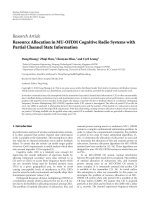
Figure 6: Overview of a binaural synthesis stage based on a mono
downmix.
Figure 5. Instead of directly applying the transmitted spatial
parameters to the output signals to generate multichannel
output, the parameters are used in a binaural analysis stage to
compute binaural parameters (using a parametric approach)
or morphed filters (using the morphed-filter approach)
that would result from the combined spatial decoding and
binaural rendering process. The binaural output signals are
subsequently generated by the binaural synthesis stage.
The binaural synthesis process is performed in a filter-
bank domain to enable independent processing of various
time-frequency tiles. The synthesis stage for a mono down-
mix using a parametric approach is outlined in Figure 6.
A hybrid QMF filter bank provides 71 down-sampled,
nonlinearly spaced subbands that can be grouped in 28
parameter bands that approximate the bandwidth of critical
bands. In case of a mono downmix, the hybrid-QMF-
domain signal is processed by a decorrelator that consists of
lattice all-pass filters to generate a signal that is statistically
independent from its input [19, 21]. In case of a stereo
downmix, the two downmix signals serve as input to the
spatial synthesis stage (without decorrelator). Subsequently,
a2
×2matrixM is applied for each subband to generate two
signals. The final binaural output is obtained by two hybrid
QMF synthesis filter banks.
The 2
× 2 binaural synthesis matrix M is computed for
each received spatial parameter set. In the case of a morphed-
filter approach, the synthesis matrix has dimensions 2
×2×N,
with N the number of “taps” in the time direction. These
matrices are defined for specific temporal positions that are
signaled in the MPEG Surround bit stream. Typical MPEG
Surround parameter update rates are in the order of 30 to
10 EURASIP Journal on Advances in Signal Processing
50 milliseconds, and the parameters are typically placed at or
near positions where spatial attributes of the audio content
show strong deviations over time.
For positions in-between parameter positions, the spatial
properties of the incoming signals are not accurately defined
and hence an interpolation scheme is required. Preferably,
the interpolation scheme has a relatively low computational
complexity such that the system could run on battery-
powered devices such as mobile audio players. From infor-
mal tests it was observed that a piecewise linear approxima-
tion of the time-varying synthesis matrix variation (i.e., by
linear interpolation of the synthesis matrix) did not have any
negative effects on the resulting quality compared to more
advanced interpolation schemes.
5.2. Evaluation (parametric approach)
5.2.1. Procedure
A listening test was pursued to evaluate the subjective quality
of the proposed parametric binaural synthesis method. In
this test, the quality of the MPEG Surround (MPS) binaural
decoding mode (“MPS binaural”) is compared to a reference
condition. This reference condition comprised convolution
of an original multichannel audio excerpt with HRIRs and
subsequent downmix to stereo. As a control condition, the
combination of MPEG Surround multichannel decoding
followed by conventional HRIR convolution was employed
(denoted “MPS + HRIR”). For all configurations in this test,
anechoic KEMAR HRIRs [43] were used with a length of 128
samples at a sampling frequency of 44.1 kHz.
For both the binaural decoding mode and the con-
trol condition, the same MPEG Surround bit stream was
employed. This bit stream was generated using a state-
of-the-art MPEG Surround encoder using a mono down-
mix configuration. This mono downmix was subsequently
encoded using a high-efficiency AAC (HE-AAC) encoder
[44] at 44 kbps. The spatial parameters generated by the
MPEG Surround decoder occupied approximately 4 kbps.
This rather low bit rate of 48 kbps total was selected
because it is foreseen that the binaural decoding mode is
especially suitable for mobile applications that are under
severe transmission bandwidth and complexity constraints.
Twelve listeners participated in this experiment. All
listeners had significant experience in evaluating audio
codecs and were specifically instructed to evaluate the overall
quality, consisting of the spatial audio quality as well as
any other noticeable artifacts. In a double-blind MUSHRA
test [45], the listeners had to rate the perceived quality of
several processed excerpts against the reference condition
(i.e., uncoded items processed with HRIRs) excerpts on a
100-point scale with 5 labels, denoted as “bad,” “poor,” “fair,”
“good,” and “excellent.” A hidden reference and the low-
pass filtered anchor (reference with a bandwidth limitation
of 3.5kHz) were also included in the test. The subjects
could listen to each excerpt as often as they liked and could
switch in real time between all versions of each excerpt. The
experiment was controlled from a PC with an RME Digi
96/24 sound card using ADAT digital out. Digital-to-analog
Table 1: Test excerpts
Excerpt Name Category
1 BBC applause Pathological/ambience
2 ARL applause Pathological/ambience
3 Chostakovitch Music
4 Fountain music Pathological/ambience
5 Glock Pathological
6 Indie2 Movie sound
7 Jackson1 Music
8 Pops Music
9 Poulenc Music
10 Rock concert Music
11 Stomp Music (with LFE)
conversion was provided by an RME ADI-8 DS 8-channel
D-to-A converter. Beyerdynamic DT990 headphones were
used throughout the test. Subjects were seated in a sound-
insulated listening room.
A total of 11 critical multichannel excerpts were used
as listed in Tabl e 1 . The excerpts are the same as used
in the MPEG Call for Proposals (CfP) on Spatial Audio
Coding [46], and range from pathological signals (designed
to be critical for the technology at hand) to movie sound
and multichannel music productions. All input and output
excerpts were sampled at 44.1 kHz.
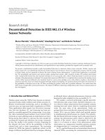
5.2.2. Results
The results of the listening test are shown in Figure 7.The
various excerpts are given along the abscissa, while the
ordinate corresponds to the average MUSHRA score across
listeners. Different symbols refer to different configurations.
The error bars denote the 95% confidence intervals of the
means.
The hidden reference (square symbols) has the highest
scores. The results for the binaural decoding mode are
denoted by the diamonds; the control condition using con-
volution is represented by the downward triangles. Although
the scores for these methods vary between 45 and 85, the
binaural decoding approach has scores that are higher than
the conventional method for all excerpts. Finally, the low-
pass anchor has the lowest scores of around 20.
Theaveragescoresforeachmethodacrosssubjectsand
excerpts are shown in Figure 8.Thedifference between the
binaural decoding mode and the control condition amounts
to 12 points in favor of the binaural decoder.
If the computational complexities of the binaural de-
coder and the conventional systems are compared, also in-
teresting differences are observed. The number of operations
(expressed in multiply-accumulates per second) amounts
to 11.1 million for the binaural decoder and 47 million
for the MPEG Surround multichannel decoder followed by
convolution using fast Fourier transforms.
JeroenBreebaartetal. 11
0
20
40
60
80
100
BBC applause
ARL applause
Chostakovitch
Fountain music
Glock
Indie2
Jackson1
Pops
Poulenc
Rock concert
Stomp
Ref
MPS binaural
MPS + HRIR
BW35
Test results (subjects: 12, items: 11, codecs: 4)
MUSHRA
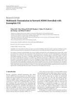
Figure 7: Subjective test results averaged across subjects for
the parametric approach. Error bars denote the 95% confidence
intervals of the means.
0
20
40
60
80
100
Ref
MPS binaural
MPS + HRIR
BW35
Test results (overall mean)
MUSHRA
Figure 8: Overall mean scores (across subjects and excerpts) for the
parametric approach.
5.2.3. Discussion
The results of the perceptual evaluation indicate that both
of the binaural rendering methods (the parametric binaural
decoding mode and the conventional HRIR convolution
method) are distinguishable from the reference. This is most
probably due to the low bit-rate (48 kbps total) that was
employed to represent the multichannel signal in MPEG
Surround format. For loudspeaker playback, the perceived
quality of MPEG Surround operating at 48 kbps has been
shown to amount 65 in other tests [15, 47]. In that respect,
the quality for the test and control conditions isin line with
earlier reports.
The parametric representation of MPEG Surround aims
at perceptual reconstruction of multichannel audio. As such,
at the bit rate that was under test, MPEG Surround does
not deliver full waveform reconstruction of the multichannel
output signals. Such waveform reconstruction requires the
use of “residual coding” as supported by MPEG Surround.
However, residual coding results in a significant increase
in the bit rate which is undesirable or even unavailable
in mobile applications. Given the low scores for MPEG
Surround decoding followed by HRIR convolution, the
multichannel signals resulting from the parametric repre-
sentation seem unsuitable for further post processing using
HRIRs. This is a property that is often observed for lossy
audio coders. The binaural decoding mode, however, which
does not rely on processing of decoded signals, outperforms
the convolution-based method, both in terms of perceived
quality and computational complexity. This clearly indicates
the advantages of parameter-domain processing compared to
the signal-domain approach.
5.3. Evaluation (morphed-filter approach)
5.3.1. Procedure
A second listening test was employed to assess the quality of
the QMF-domain morphed-filter approach. The reference,
control, test and anchor conditions were generated in the
same way as described in Section 5.2.1, however with the
following modifications to reflect a different application
scenario, that is, that of an online music store. In this
application scenario, multichannel audio is encoded using
the MPEG Surround format employing a stereo downmix
to ensure stereo backward compatibility. The down-mix was
encoded using AAC at a bit of 160 kbps, a common bit rate
for stereo content in online music stores, while the MPEG
Surround parameter bit rate was set to 12 kbps. In the current
test, echoic BRIRs were employed that were also used in the
MPEG selection tests [48]. The test procedure and excerpts
are identical to those employed in the previous test. A total
of 12 subjects participated in this test.
5.3.2. Results
The results of the listening test for individual excerpts are
shown in Figure 9.Thevariousexcerptsaregivenalong
the abscissa, while the ordinate corresponds to the average
MUSHRA score across listeners. Different symbols refer to
12 EURASIP Journal on Advances in Signal Processing
0
20
40
60
80
100
BBC applause
ARL applause
Chostakovitch
Fountain music
Glock
Indie2
Jackson1
Pops
Poulenc
Rock concert
Stomp
Ref
MPS binaural
MPS + HRIR
BW35
Test results (subjects: 12, items: 11, codecs: 4)
MUSHRA
Figure 9: Subjective test results averaged across subjects for the
morphed-filter approach. Error bars denote the 95% confidence
intervals of the means.
different configurations. The error bars denote the 95%
confidence intervals of the means.
The trend observed in Figure 9 is very similar to the
one observed for the parametric approach in Figure 7.The
hidden reference (squares) has scores around 100. The
MPEG Surround binaural decoding mode (diamonds) has
scores between 77 and 95 and has in all cases a higher
mean across subjects than the control condition (downward
triangles).
Themeanacrosssubjectsandexcerptsforeachcon-
figuration is shown in Figure 10. On average, the MPEG
Surround binaural decoding mode scores about 90, which
is roughly 10 MUSHRA points higher than the control
condition.
The computational complexity of the morphed-filter
approach in this case amounts to 41 million operations,
compared to 47 million for the control condition (MPEG
Surround multichannel output followed by BRIR convolu-
tion in the FFT domain).
5.3.3. Discussion
In analogy to the test results for the parametric approach,
the QMF-domain filtering method achieves a higher quality
than the control condition (i.e., multichannel decoding and
subsequent HRTF or BRIR convolution). Hence, for both
0
20
40
60
80
100
Ref
MPS binaural
MPS + HRIR
BW35
Test results (overall mean)
MUSHRA
Figure 10: Overall mean scores (across excerpts and subjects) for
the morphed-filter approach. Error bars denote the 95% confidence
intervals of the means.
methods, it is beneficial to combine the spatial decoding
and binaural rendering processes to achieve maximum
perceptual quality.
The overall scores for the QMF-domain filtering
approach are higher than those for the parametric method.
This difference can be attributed to several factors.
(i) The employed binaural rendering method. The para-
metric approach employs a lossy HRTF representa-
tion, while the QMF-domain filtering method results
in a more accurate representation of the original
impulse response.
(ii) The spatial parameter bit rate. In the second test, the
bit rate used for spatial parameters is higher than the
bit rate employed in the first test, which results in
a more accurate representation of the multichannel
audio content.
(iii) The downmix configuration. In the second test, a
stereo downmix was employed, while in the first
test, one single audio channel was used as downmix
signal. MPEG Surround will in most cases achieve a
higher quality for stereo downmixes than for mono
downmixes.
(iv) The bit rate of the core coder. In the first test,
44 kbps was used to encode the mono signal, while
in the second test, 160 kbps was available for the
stereo signal. Hence the perceptual quality of the
transmitted downmix is higher for the second test
than for the first test.
JeroenBreebaartetal. 13
Although it is difficult to assess the effect of the individual
factors on the resulting quality based on the current test
results, it is expected that the downmix coder (and the
associated channel configuration) has quite a large effect
on the overall quality, a trend that can also be observed in
loudspeaker reproduction test results published in [17, 18].
6. CONCLUSIONS
Two novel methods for binaural rendering based on para-
metric representations were outlined. In contrast to con-
ventional, convolution-based methods, HRTFs or BRTFs are
transformed to the parameter domain or filterbank domain
and combined with parameters that describe the statistical
properties of the various signals, which are radiated by
virtual sources. From this combination, a 2
× 2matrix
operation (including the option to have taps in the time
direction) is derived that converts a mono (using an addi-
tional decorrelator circuit) or stereo downmix to a binaurally
rendered signal without the need of individual source signals
as intermediate step.
The proposed method can be easily integrated with
parametric multichannel audio coders (MPEG Surround)
that rely on interchannel cues such as level differences
and interchannel correlations. Results of a listening test
revealed that the proposed method outperforms conven-
tional, convolution-based methods in terms of perceived
quality and computational complexity. These properties,
combined with the unsurpassed compression efficiency of
MPEG Surround, make the proposed method very suitable
for mobile applications.
ACKNOWLEDGMENT
The authors would like to thank the anonymous reviewers
and the associate editor for their thorough reading and
valuable comments and suggestions for improving the
manuscript.
REFERENCES
[1] D. R. Begault, 3-D Sound for Virtual Reality and Multimedia,
Academic Press, Cambridge, Mass, USA, 1994.
[2] J. Blauert, Spatial Hearing: The Psychophysics of Human Sound
Localization, MIT Press, Cambridge, Mass, USA, 1997.
[3] P. Rubak, “Headphone signal processing system for out-of-the
head localization,” in Proceedings of the 90th AES Convention,
Paris, France, January 1991, in paper 3063.
[4] F. Rumsey, Spatial Audio, Focal Press, Oxford, UK, 2001.
[5] F. L. Wightman and D. J. Kistler, “Headphone simulation
of free-field listening—I: stimulus synthesis,” Journal of the
Acoustical Society of America, vol. 85, no. 2, pp. 858–867, 1989.
[6] B. G. Shinn-Cunningham, “Applications of virtual auditory
displays,” in Proceedings of the 20th Annual International
Conference of the IEEE Engineering in Medicine and Biology
Society (EMBS ’98), vol. 3, pp. 1105–1108, Hong Kong,
October-November 1998.
[7] P. Minnaar, S. K. Olesen, F. Christensen, and H. Møller, “The
importance of head movements for binaural room synthesis,”
in Proceedings of the International Conference on Auditory
Display (ICAD ’01), Espoo, Finland, July-August 2001.
[8] B. G. Shinn-Cunningham, “The perceptual consequences
of creating a realistic, reverberant 3-D audio display,” in
Proceedings of t he International Congress on Acoustics (ICA ’04),
Kyoto, Japan, April 2004.
[9] H. Møller, D. Hammershøi, C. B. Jensen, and M. F. Sørensen,
“Evaluation of artifical heads in listening tests,” Journalofthe
Audio Engineering Society, vol. 47, no. 3, pp. 83–100, 1999.
[10] H. Møller, M. F. Sørensen, C. B. Jensen, and D. Hammershøi,
“Binaural technique: do we need individual recordings?”
Journal of the Audio Engineering Society, vol. 44, no. 6, pp. 451–
469, 1996.
[11] F. L. Wightman and D. J. Kistler, “Individual differences
in human sound localization behavior,” The Journal of the
Acoustical Society of America, vol. 99, no. 4, pp. 2470–2500,
1996.
[12] J M. Jot, M. Walsh, and A. Philp, “Binaural simulation of
complex acoustic scenes for interactive audio,” in Proceedings
of the 121st AES Convention, San Francisco, Calif, USA,
October 2006, in paper 6950.
[13] ISO/IEC JTC1/SC29/WG11, “MPEG audio technologies—
part 1: MPEG surround,” ISO/IEC FDIS 23003-1:2006(E),
2004.
[14] J. Breebaart and C. Faller, Spat ial Audio Processing: MPEG Sur-
round and Other Applications, John Wiley & Sons, Chichester,
UK, 2007.
[15] J. Breebaart, J. Herre, C. Faller, et al., “MPEG spatial audio
coding / MPEG surround: overview and current status,” in
Proceedings of the 119th AES Convention,NewYork,NY,USA,
October 2005, in paper 6599.
[16] J. Breebaart, G. Hotho, J. Koppens, E. Schuijers, W. Oomen,
and S. van de Par, “Background, concept, and architecture for
the recent MPEG surround standard on multichannel audio
compression,” Journal of the Audio Engineering Society, vol. 55,
no. 5, pp. 331–351, 2007.
[17] J. Herre, K. Kj
¨
orling, J. Breebaart, et al., “MPEG surround—
the ISO/MPEG standard for efficient and compatible multi-
channel audio coding,” in Proceedings of the 122th AES
Convention, Vienna, Austria, May 2007.
[18] J. R
¨
od
´
en, J. Breebaart, J. Hilpert, et al., “A study of the MPEG
surround quality versus bit-rate curve,” in Proceedings of the
123rd AES Convention, New York, NY, USA, October 2007.
[19] E. Schuijers, J. Breebaart, H. Purnhagen, and J. Engdeg
˚
ard,
“Low complexity parametric stereo coding,” in
Proceedings
of the 116th AES Convention, Berlin, Germany, May 2004, in
paper 6072.
[20] J. Breebaart, S. van de Par, A. Kohlrausch, and E. Schuijers,
“Parametric coding of stereo audio,” EURASIP Journal on
Applied Signal Processing, vol. 2005, no. 9, pp. 1305–1322,
2005.
[21] J. Engdeg
˚
ard, H. Purnhagen, J. R
¨
od
´
en, and L. Liljeryd, “Syn-
thetic ambience in parametric stereo coding,” in Proceedings of
the 116th AES Convention, Berlin, Germany, May 2004.
[22] H. Purnhagen, “Low complexity parametric stereo coding in
MPEG-4,” in Proceedings of the 7th International Conference on
Dig ital Audio Effects (DAFx ’04), Naples, Italy, October 2004,
/>[23] H. Purnhagen, J. Engdegard, W. Oomen, and E. Schuijers,
“Combining low complexity parametric stereo with high
efficiency AAC,” ISO/IEC JTC1/SC29/WG11 MPEG2003/
M10385, December 2003.
[24] E. Schuijers, W. Oomen, B. den Brinker, and J. Breebaart,
“Advances in parametric coding for high-quality audio,” in
14 EURASIP Journal on Advances in Signal Processing
Proceedings of the 114th AES Convention,Amsterdam,The
Netherlands, March 2003, in paper 5852.
[25] G. Hotho, L. Villemoes, and J. Breebaart, “A stereo backward
compatible multi-channel audio codec,” IEEE Transactions on
Audio, Speech and Language Processing, vol. 16, pp. 83–93,
2008.
[26] F. Baumgarte and C. Faller, “Binaural cue coding—part I:
psychoacoustic fundamentals and design principles,” IEEE
Transactions on Speech and Audio Processing,vol.11,no.6,pp.
509–519, 2003.
[27] C. Faller and F. Baumgarte, “Binaural cue coding—part II:
schemes and applications,” IEEE Transactions on Speech and
Audio Processing, vol. 11, no. 6, pp. 520–531, 2003.
[28] F. L. Wightman and D. J. Kistler, “Headphone simulation of
free-field listening—II: psychophysical validation,” Journal of
the Acoustical Society of America, vol. 85, no. 2, pp. 868–878,
1989.
[29]F.L.WightmanandD.J.Kistler,“Resolutionoffront-
back ambiguity in spatial hearing by listener and source
movement,” Journal of the Acoustical Society of America,
vol. 105, no. 5, pp. 2841–2853, 1999.
[30] D. S. Brungart, N. I. Durlach, and W. M. Rabinowitz,
“Auditory localization of nearby sources—II: localization of a
broadband source,” Journal of the Acoustical Society of America,
vol. 106, no. 4, pp. 1956–1968, 1999.
[31] B. G. Shinn-Cunningham, S. Santarelli, and N. Kopco, “Tori
of confusion: binaural localization cues for sources within
reach of a listener,” Journal of the Acoustical Society of America,
vol. 107, no. 3, pp. 1627–1636, 2000.
[32] W. M. Hartmann and A. Wittenberg, “On the externalization
of sound images,” Journal of the Acoustical Society of America,
vol. 99, no. 6, pp. 3678–3688, 1996.
[33] E. H. A. Langendijk and A. W. Bronkhorst, “Fidelity of three-
dimensional-sound reproduction using a virtual auditory
display,” Journal of the Acoustical Society of America, vol. 107,
no. 1, pp. 528–537, 2000.
[34] F. L. Wightman and D. J. Kistler, “The dominant role of low-
frequency interaural time differences in sound localization,”
Journal of the Acoustical Socie ty of America, vol. 91, no. 3, pp.
1648–1661, 1992.
[35] A. Kulkarni and H. S. Colburn, “Role of spectral detail in
sound-source localization,” Nature, vol. 396, no. 6713, pp.
747–749, 1998.
[36] A. Kulkarni, S. K. Isabelle, and H. S. Colburn, “Sensitivity
of human subjects to head-related transfer-function phase
spectra,” Journal of the Acoustical Society of America, vol. 105,
no. 5, pp. 2821–2840, 1999.
[37] J. Breebaart, Modeling binaural signal de tection, Ph.D. thesis,
Eindhoven University of Technology, Eindhoven, The Nether-
lands, 2001.
[38] J. Breebaart and A. Kohlrausch, “The perceptual (ir)relevance
of HRTF magnitude and phase spectra,” in Proceedings of the
110th AES Convention, Amsterdam, The Netherlands, May
2001, in paper 5406.
[39] J. Huopaniemi and N. Zacharov, “Objective and subjective
evaluation of head-related transfer function filter design,”
Journal of the Audio Engineering Society, vol. 47, no. 4, pp. 218–
239, 1999.
[40] B. R. Glasberg and B. C. J. Moore, “Auditory filter shapes
in forward masking as a function of level,” Journal of the
Acoustical Society of America, vol. 71, no. 4, pp. 946–949, 1982.
[41] ITU-R, “Multichannel stereophonic sound system with and
without accompanying picture,” ITU-R Recommend. BS.775-
1, 1994.
[42] L. Villemoes, “Efficient filtering with a complex modulated
filterbank,” in Patent application WO2007/085275A1, 2007.
[43] B. Gardner and K. Martin, “HRTF measurements of a KEMAR
dummy-head microphone,” Perceptual Computing Technical
Report 280, MIT Media Lab, Cambridge, Mass, USA, 1994.
[44] M. Wolters, K. Kj
¨
orling, D. Homm, and H. Purnhagen, “A
closer look into MPEG-4 high efficiency AAC,” in Proceedings
of the 115th AES Convention, Los Angeles, Calif, USA, October
2003, in paper 5871.
[45] ITU-R, “Method for the subjective assessment of intermediate
quality level of coding systems (MUSHRA),” ITU-R Recom-
mend. BS.1534, 2001.
[46] ISO/IEC JTC1/SC29/WG11, “Call for proposals on spatial
audio coding,” ISO/IEC JTC1/SC29/WG11 N6455, October
2004.
[47] L. Villemoes, J. Herre, J. Breebaart, et al., “MPEG surround:
the forthcoming ISO standard for spatial audio coding,” in
Proceedings of the 28th AES Conference, pp. 213–230, Pitea,
Sweden, June-July 2006.
[48] ISO/IEC JTC1/SC29/WG11, “Report on MPEG spatial audio
coding RM0 listening tests,” ISO/IEC JTC1/SC29/WG11
N7138, 2005.