Báo cáo hóa học: " Research Article Design and Performance of Cyclic Delay Diversity in UWB-OFDM Systems" docx
Bạn đang xem bản rút gọn của tài liệu. Xem và tải ngay bản đầy đủ của tài liệu tại đây (840.39 KB, 8 trang )
Hindawi Publishing Corporation
EURASIP Journal on Wireless Communications and Networking
Volume 2008, Article ID 541478, 8 pages
doi:10.1155/2008/541478
Research Article
Design and Performance of Cyclic Delay Diversity in
UWB-OFDM Systems
Poramate Tarasak, Khiam-Boon Png, Xiaoming Peng, and Francois Chin
Institute for Infocomm Research, 21 Heng Mui Keng Terrace, Singapore 119613
Correspondence should be addressed to Poramate Tarasak,
Received 14 June 2007; Revised 20 October 2007; Accepted 9 December 2007
Recommended by Stefan Kaiser
This paper addresses cyclic delay diversity (CDD) in an ultra-wideband communication system based on orthogonal frequency
division multiplexing (OFDM) technique. Symbol error rate and outage probability have been derived. It is shown that with only
two transmit antennas, CDD effectively improves SER performance and reduces outage probability significantly especially when
the channel delay spread is short. Both simulation and analytical results agree well in all considered cases. The selection of delay
times for CDD is also addressed for some special cases.
Copyright © 2008 Poramate Tarasak et al. This is an open access article distributed under the Creative Commons Attribution
License, which permits unrestricted use, distribution, and reproduction in any medium, provided the original work is properly
cited.
1. INTRODUCTION
Wireless personal area network (WPAN) using ultra-
wideband (UWB) communication has received great inter-
est due to its capability of transmitting very high bit rate
over short range. Conventional UWB technique transmits
very short pulses in a time-hopping manner with low-duty
cycle [1]. In addition to high bit rate transmission, due to
its short-pulse structure, UWB also has high precision lo-
calization capability. However, pulse-based UWB system can
be very difficult to implement since it requires analog-to-
digital and digital-to-analog converters with very high sam-
pling rate when very high-transmission rate is needed. Al-
ternate UWB technique, so-called multiband OFDM (MB-
OFDM), was proposed to divide the wide bandwidth into
smaller bands. The OFDM symbols are transmitted across
the bands according to time-frequency code [2]. MB-OFDM
has been adopted in the WiMedia standard as a transmission
technique for UWB systems becoming ISO standard [3]. This
latter technique will be considered in this paper.
To enhance system performance, multiple antennas
could be applied with the UWB system to obtain spatial di-
versity. However, multiple-antenna technique typically in-
curs higher complexity at both transmitter and receiver.
Cyclic delay diversity (CDD), which is a low-complexity di-
versity scheme for OFDM systems [4, 5], is more suitable for
UWB system. Although CDD can be applied equivalently at
either transmitter or receiver, this paper will only focus on
CDD at the transmitter. CDD adds a deterministic delay to
the effective part of the OFDM symbol after IFFT process-
ing at each transmit antenna. The time delay results in phase
rotation in the frequency domain among the subcarriers. By
choosing appropriate delay times, the CDD scheme is able to
achieve a reduced correlation of the effective frequency re-
sponse. That means CDD yields higher-frequency selectiv-
ity and then the error performance is improved when cod-
ing is applied across subcarriers. Effectively, CDD converts
spatial diversity associated with multiple transmit antennas
into frequency diversity in the equivalent single antenna sys-
tem. This technique is elegant and beneficial because diver-
sity gain can be achieved without modification at the receiver
(or at the transmitter in the case of CDD applied at the re-
ceiver). Therefore, it has received considerable attention in
the system design where backward compatibility is an im-
portant issue. In addition, compared to space-frequency cod-
ing technique, CDD requires only one IFFT processor at the
transmitter regardless of the number of transmit antennas
while space-frequency coding requires the number of IFFT
processors equal to the number of transmit antennas. Re-
cently, the impact of channel fading correlation on the per-
formance of CDD has been investigated in [6].
Research on UWB with MB-OFDM technique is rela-
tively new compared to that with pulse-based technique. Re-
cent efforts to improve the system performance include using
2 EURASIP Journal on Wireless Communications and Networking
advanced coding or multiple antennas. Low-density parity-
check code (LDPC code) for MB-OFDM has been evalu-
ated in [7] and a simplified LDPC has also been proposed
to achieve low complexity without sacrificing performance.
Reference [8] evaluates the performance of space-time block
code (STBC) and convolutional STBC (CC-STBC) on a
seriesofchannelmodelsatdifferent rates and concludes
that CC-STBC can be considered for extreme channel en-
vironment. Reference [9] investigates concatenated Reed-
Solomon and convolutional codes and shows that it out-
performs the convolutional code at high SNR. More re-
cently, MIMO technique and cooperative communication
have been applied to UWB system, for example, [10, 11]. No-
tably, [11] applies decode-and-forward protocol to improve
communication range and reduce power consumption.
This paper exploits CDD which aims to improve the per-
formance of UWB-OFDM system with low complexity. We
adopt the channel model similar to [12] which includes the
effects of multipath clustering and Poisson arrival of multi-
path components inherited in UWB channels. Based on the
framework in [12], symbol error rate (SER) and outage prob-
ability have been derived for the CDD case. Some compli-
cation in the evaluation of outage probability that was not
found in [12] is also addressed. Simulation and analytical
results show that CDD improves the SER performance and
reduces outage probability significantly due to its diversity
advantage. The results clearly indicate the performance de-
pending on channel environment and number of coded sym-
bols across subcarriers. Since delay time selection has signifi-
cant influence to the performance, the optimum delay times
to minimize SER are proposed which minimize the determi-
nant of the correlation matrix of the effective channel. It is
also shown that the selection approach in [4]isoptimum
when the number of transmit antennas is equal to the num-
ber of coded symbols across subcarriers at high E
b
/N
0
region.
The paper is organized as follows. Section 2 presents sys-
tem and channel models. Section 3 discusses the application
of CDD. Section 4 derives the SER and outage probability.
Section 5 shows simulation results and draws some discus-
sions. Section 6 addresses the issue of delay time selection.
Conclusion is given in Section 7. The notations in this paper
will closely follow those in [12] for consistency.
2. SYSTEM MODEL
We consider a point-to-point communication system using
UWB-OFDM system. Although this paper considers a single-
band approach, multiband OFDM can be readily extended
[12]. The following briefly explains the channel model and
signal model taken from [12].
2.1. Channel model
The channel model in [12] is based on the Saleh-Valenzuela
(S-V) model for indoor environment. Let h(t) be an impulse
response which can be written as
h(t)
=
C
c=0
L
l=0
α(c, l)δ
t − T
c
− τ
c,l
,(1)
where α(c, l) is the lth multipath component of the cth clus-
ter, T
c
is the delay of the cth cluster, and τ
c,l
is the delay of
α(c, l)relativetoT
c
. According to (1), the total number of
clusters is C +1 and the total number of channel taps is L +1.
Both cluster arrival and multipath arrival follow Poisson dis-
tribution with rate Λ and λ, respectively. Note that it is possi-
ble for clusters to be overlapped. α(c, l) are zero-mean com-
plex Gaussian random variables whose variances are
Ω
c,l
= E
α(c, l)
2
=
Ω
0,0
e
−T
c
/Γ−τ
c, l
/γ
,(2)
where Ω
0,0
is the mean energy of the first path of the first
cluster, Γ and γ are power decay factors for cluster and mul-
tipath, respectively. E[
·] is an expectation. For a fair com-
parison, total multipath energy is normalized to one, that is,
C
c=0
L
l=0
Ω
c,l
= 1.
Comparing with the standard channel model in
IEEE802.15.3a [13], two main differences are observed. First,
α(c, l) is Gaussian distributed as opposed to log-normal dis-
tributed. Second, the log-normal shadowing effect has been
neglected. Nevertheless, the potential advantage of CDD
should be valid on a more realistic channel model as well.
2.2. Signal model
Assuming perfect synchronization and channel estimation
at the receiver, the received signal at nth subcarriers, n
=
0, 1, , N − 1, after removing cyclic prefix and performing
FFT is
y(n)
=
E
s
d(n)H(n)+z(n), (3)
where E
s
is the symbol energy, d(n) is a transmitted symbol.
z(n) is a zero-mean complex Gaussian noise with variance N
0
. H(n) is the channel transfer function at the nth subcarrier
obtained from
H(n)
=
C
c=0
L
l=0
α(c, l)exp
−
j2πnΔ f
T
c
+ τ
c, l
,(4)
where j
=
√
−1, Δ f is the subcarrier spacing. The above
signal model corresponds to conventional UWB-OFDM sys-
tem. The signal model for CDD will be described in the next
section.
In this paper, we are considering the coded system with
and without CDD. The code used is a repetition code based
on a symbol level which is achieved by repeating the symbols
on adjacent subcarriers. The symbols are repeated M times
in the case of coding across M subcarriers resulting in code
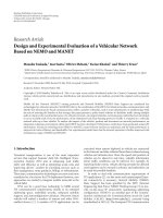
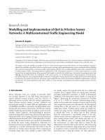
rate 1/M . Figure 1 shows the block diagrams of a transmitter
with/without CDD and a receiver considered in this paper.
3. CYCLIC DELAY DIVERSITY
We are considering the system with N
t
transmit antennas and
single receive antenna. At the transmitter, CDD makes N
t
copies of a transmit stream after IFFT processing of a coded
symbol stream, where N
t
is the number of transmit antennas.
At each antenna, each copy of the OFDM symbol is cycli-
cally delayed by δ
n
t
, that is, part of the symbol that has been
Poramate Tarasak et al. 3
Data
stream
QPSK
mapping
Repetition
code
IFFT
GI
insertion
(a)
Data
stream
QPSK
mapping
Repetition
code
IFFT
Cyclic
delay
Cyclic
delay
GI
insertion
GI
insertion
(b)
GI
removal
FFT
ML
decoder
Data
stream
(c)
Figure 1: (a) A transmitter without CDD. (b) A transmitter with CDD (two transmit antennas). (c) A receiver for UWB-OFDM system.
delayed beyond an OFDM symbol period is added at the be-
ginning [4]. Then cyclic prefix of length longer than the delay
spread (guard interval) is added at each antenna. All streams
are transmitted simultaneously.
Since cyclic delay is done on the time-domain signal, it
corresponds to phase rotation in the frequency domain. At
the receiver, the channel transfer function appears to be a su-
perposition of channel transfer functions from all transmit
antennas with the corresponding phase shifts [4],
H
eff
(n) =
N
t
−1
n
t
=0
H
n
t
(n)exp
−
j
2πδ
n
t
n
N
,(5)
where H
eff
(n) denotes the effective channel, H
n
t
(n)denotes
the channel transfer function from the n
t
th antenna. For
a fair comparison, the transmitted symbol energy must be
scaled by 1/
N
t
so the total signal energy remains unchanged
compared to a single-antenna system. It can be readily seen
from (5) that H
eff
(n) has higher fluctuation and therefore a
higher amount of frequency diversity when coding is applied
across the subcarriers.
Selection of
{δ
n
t
} is an important issue that affects the
performance of CDD. Witrisal et al. [4] proposed selection
of delays from
δ
n
t
= n
t
·
N
N
t
,(6)
assuming N
t
divides N. This choice yields largest delay dif-
ferences and zero correlation between adjacent N
t
subcarri-
ers [4]. This choice of delay times will be further justified in
Section 6.
Regarding coding to be used, [14] comments on the min-
imum N
t
which must be N
t
≤ d
f
,whered
f
is the minimum
distance of the coded symbols. With a repetition code rate
1/M, this condition becomes N
t
≤ M, otherwise, CDD can-
not achieve full-diversity advantage. Therefore, we will con-
sider only the case where this condition is satisfied.
4. SYMBOL ERROR RATE AND OUTAGE
PROBABILITY ANALYSIS
In this section, we derive pairwise error probability (PEP)
and outage probability for the CDD cases.
4.1. Pairwise error probability
PEP in this section is the probability of decoding to an er-
ror symbol
d(n) instead of the transmitted symbol d(n).Let
the Euclidean distance between these two symbols be ν
n
. The
received signal is rewritten in a matrix form as
Y
=
E
s
/N
t
X(D)H
eff
+ Z,(7)
where Y
= [y(0) y(1) ··· y(M − 1)]
t
,(·)
t
is a trans-
pose operation, X(D)
= diag(d(0), d(1), , d(M − 1))
is an M
× M diagonal matrix with the [d(0),d(1), ,
d(M
−1)] as its main diagonal. The M×1 channel vector H
eff
represents the effective channel transfer function which is
[H
eff
(0), H
eff
(1), , H
eff
(M −1)]
t
corresponding to M sym-
bol intervals. The M
×1vectorZ = [z(0) z(1) ··· z(M −
1)]
t
is a noise vector. With maximum likelihood decoder, the
decision rule is
D = arg min
D
Y −
E
s
/N
t
X(D)H
eff
2
,(8)
where
· denotes the Frobenius norm.
Follow the same line of derivation in [12], let us de-
fine a correlation matrix of the effective channel, R
eff
M
=
E[H
eff
H
eff
H
]. (·)
H
is a conjugate transpose operation. The
PEP of CDD of a UWB-OFDM system is readily obtained
as [12,Theorem2]
P
e
≈
1
π
π/2
0
M
n=1
1+
ρν
n
4N
t
sin
2
θ
eig
n
R
eff
M
−1
dθ,(9)
where ρ
= E
s
/N
0
,eig
n
(R
eff
M
)isnth eigenvalue of the matrix
R
eff
M
. The integration over the variable θ comes from using an
alternate representation of Q function [12].
To fi n d R
eff
M
, H
eff
is written as
H
eff
= ΞH , (10)
4 EURASIP Journal on Wireless Communications and Networking
where H = [H
0
(0), H
1
(0), , H
N
t
−1
(0), , H
0
(M − 1),
H
1
(M−1), , H
N
t
−1
(M−1)]
t
. Ξ is an M×N
t
M phase matrix
written as
Ξ
=
⎡
⎢
⎢
⎢
⎢
⎣
φ(0) 0
1×N
t
··· 0
1×N
t
0
1×N
t
φ(1) ··· 0
1×N
t
.
.
.
.
.
.
.
.
.
.
.
.
0
1×N
t
0
1×N
t
··· φ(M −1)
⎤
⎥
⎥
⎥
⎥
⎦
, (11)
where φ(n)isa1
× N
t
phase vector, φ(n) = [exp(−
j(2πδ
0
n/N)),exp(−j(2πδ
1
n/N)), ,exp(−j(2πδ
N
t
−1
n/
N))], 0
1×N
t
is a 1 × N
t
all-zero vector. Therefore, the
correlation matrix R
eff
M
is found from
R
eff
M
= E[H
eff
H
eff
H
] = E[Ξ HH
H
Ξ
H
]
= ΞE[HH
H
]Ξ
H
= Ξ(R
M
⊗ I
N
t
)Ξ
H
,
(12)
where I
N
t
is an N
t
×N
t
identity matrix, ⊗is a Kronecker prod-
uct and
R
M
=
⎡
⎢
⎢
⎢
⎢
⎣
1 R(1)
∗
··· R(M − 1)
∗
R(1) 1 ··· R(M − 2)
∗
.
.
.
.
.
.
.
.
.
.
.
.
R(M
− 1) R(M −2) ··· 1
⎤
⎥
⎥
⎥
⎥
⎦
, (13)
which corresponds to the correlation matrix of the channel
transfer function in the single antenna case. Each element
R(m)canbefoundfrom[12]
R(m)
= Ω
0, 0
·
Λ + g (1/Γ, m)
g (1/Γ, m)
·
λ + g (1/γ, m)
g (1/γ, m)
, (14)
where g(a, m)
= a+j2πmΔ f.From the PEP, SER can be com-
puted using a well-known union bound, that is, by summing
the PEP corresponding to each incorrect symbol.
4.2. Outage probability
Outage probability for CDD case is defined as the probabil-
ity that the combined effective SNR falls below a specified
threshold ζ
0
. The combined SNR in this case is
ζ
=
ρ
N
t
M
M−1
n=0
H
eff
(n)
2
, (15)
where ρ
= E
s
/N
0
is the SNR per transmitted symbol. There-
fore, the outage probability can be expressed as
P
out
= P
ζ ≤ ζ
0
= P
ξ
eff
≤
MN
t
ζ
0
ρ
=
(MN
t
ζ
0
/ρ)
0
p
ξ
eff
(x)dx,
(16)
where ξ
eff
=
M−1
n
=0
|H
eff
(n)|
2
and p
ξ
eff
(x) is the probability
density function of ξ
eff
. Following the approach in [12], we
have to find the moment-generating function (MGF) and do
inverse Laplace transform in order to obtain p
ξ
eff
(x) and then
find P
out
. Having done so, we may arrive at the MGF and
outage probability, respectively, as [12]
M
ξ
eff
(s) =
M
n=1
1
1 − seig
n
(R
eff
M
)
=
M
n=1
A
n
1 − seig
n
(R
eff
M
)
,
(17)
P
out
=
M
n=1
A
n
1 − exp
−
ζ
0
MN
t
ρeig
n
(R
eff
M
)
,
(18)
where
A
n
=
M
n
=1,n
/
=n
eig
n
(R
eff
M
)
eig
n
(R
eff
M
) − eig
n
(R
eff
M
)
. (19)
However, for (18) to be valid, all eig
n
(R
eff
M
) must be dis-
tinct. This is a striking difference between CDD and the case
in [12]. For CDD case, we have to do it is possible that some
eigenvalues will be the same and repeated roots will appear
in the denominator of (17). In such cases, partial fraction
and higher-order inverse Laplace transform according to the
obtained eigenvalues case by case.
For example, in the case of 128-point FFT, two trans-
mit antennas and coding across four subcarriers, that is,
N
= 128, N
t
= 2, M = 4, δ
0
= 0, δ
1
= 64, we will have
eig
1
(R
eff
4
) = eig
2
(R
eff
4
) = 0.816 and eig
3
(R
eff
4
) = eig
4
(R
eff
4
) =
3.184. The P
out
can be readily obtained as
P
out
=
n=1,3
B
2
n
1 −
8ζ
0
ρeig
n
R
eff
4
exp
−
8ζ
0
ρeig
n
R
eff
4
−
exp
−
8ζ
0
ρeig
n
R
eff
4
−
2C
n
1 − exp
−
8ζ
0
ρeig
n
R
eff
4
,
(20)
where
B
1
=
eig
1
R
eff
4
eig
1
R
eff
4
− eig
3
R
eff
4
,
B
3
=
eig
3
R
eff
4
eig
3
R
eff
4
− eig
1
R
eff
4
,
C
1
=
eig
1
R
eff
4
eig
3
R
eff
4
·
B
3
1
, C
3
=
eig
3
R
eff
4
eig
1
R
eff
4
·
B
3
3
.
(21)
Other cases can be similarly derived with some tedious
manipulations.
5. SIMULATION AND ANALYTICAL RESULTS
The SER and outage probability are evaluated using CM1
and CM4 channel models. CM1 and CM4 are statistical
Poramate Tarasak et al. 5
20151050
E
b
/N
0
(dB)
10
−4
10
−3
10
−2
10
−1
10
0
SER
CM1
CM4
CM1, CDD
CM4, CDD
CM1 (analysis)
CM4 (analysis)
CM1, CDD (analysis)
CM4, CDD (analysis)
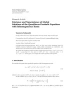
Figure 2: Symbol error rate of UWB-OFDM system. Jointly encod-
ing across two subcarriers. CDD with two transmit antennas.
channel models whose parameters are defined to match the
actual measurement data. CM1 corresponds to the indoor
short range (0–4 m) line-of-sight scenario while CM4 cor-
responds to the indoor long-range (10 m) and extreme non-
line-of-sight scenario [13]. The parameters of CM1 are Λ
=
0.0233 ×10
9
, λ = 2.5 ×10
9
, Γ = 7.1 ×10
−9
, γ = 4.3 ×10
−9
;
and the parameters of CM4 are Λ
= 0.00667 × 10
9
, λ =
2.1×10
9
, Γ = 24.0×10
−9
, γ = 12×10
−9
. SER is plotted ver-
sus E
b
/N
0
while outage probability is plotted versus the nor-
malized SNR
= ρ/ζ
0
. Since CM4 channel transfer function
is more fluctuated than that of CM1, it gives a better per-
formance when proper cyclic prefix is used under the con-
dition of perfect channel estimation. (CM4 requires longer
cyclic prefix than CM1 does to avoid intersymbol interfer-
ence.) The UWB system has N
= 128 subcarriers and each
subband has 528 MHz bandwidth. The subcarrier spacing
Δ f
= 4.125MHz The data bits are mapped to QPSK sym-
bols; and repetition code is done by repeating the symbol
over M subcarriers.
For CDD, we assume two transmit antennas. With the
condition in (6), the delay values of δ
0
= 0, δ
1
= 64 are fixed
in all cases. All simulation results are plotted as solid lines
while analytical results are plotted as dashed lines.
Figure 2 shows SER of UWB-OFDM system with jointly
encoding across two subcarriers. The performance of CDD
achieves about 6 dB gain and 4 dB gain on CM1 and CM4
channels, respectively. For CDD with CM1, there is a clear
improvement due to diversity advantage as seen from the
steeper slopes of the curves. For CDD with CM4, the curves
remain at the same slope but with an additional coding
gain as shown from the horizontal shift of the curves. It
is observed that with CDD, CM1, and CM4 have the same
SER performance. This attributes to the fact that the delay
20151050
Normalized SNR (dB)
10
−4
10
−3
10
−2
10
−1
10
0
Outage probability
CM1
CM4
CM1, CDD
CM4, CDD
CM1 (analysis)
CM4 (analysis)
CM1, CDD (analysis)
CM4, CDD (analysis)
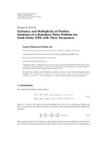
Figure 3: Outage probability of UWB-OFDM system. Jointly en-
coding across two subcarriers. CDD with two transmit antennas.
time according to [4] causes the uncorrelated Rayleigh fad-
ing across two adjacent subcarriers regardless of the chan-
nels, which is the best case for M
= 2 . All simulation
results validate the analytical results over the whole SNR
range.
Figure 3 shows the outage probability of UWB-OFDM
system with jointly encoding across two subcarriers. At out-
age probability of 10
−2
, CDD obtains about 6.3 dB gain and
2.3 dB gain on the CM1 and CM4 channels, respectively. The
improvement in outage probability is similar to the SER case.
The slope is steeper in the CM1 case while there is a horizon-
tal shift in the CM4 case. Both CM1 and CM4 with CDD have
the same outage probability for the same reason explained
for SER. Analytical results match very well to the simulation
results.
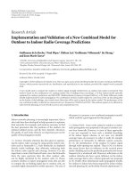
Figures 4 and 5 depict the respective SER performance
and outage probability for the case of jointly encoding across
four subcarriers. The gaps between CM1 and CM4 per-
formance with/without CDD become larger than those in
Figure 3.AtSERof10
−3
, CDD achieves 6 dB gain on the
CM1 channel and 2.2 dB gain on the CM4 channel. Unlike
Figures 2 and 3, it is seen that there is a performance dif-
ference between the CM1 and CM4 channels in the case of
CDD. Therefore, coding over higher number of subcarriers
leads to significant performance gain of CDD. Analytical and
simulation results agree to each other.
We have also evaluated the frame error rate (FER) of
a half rate punctured convolutional code with constraint
length 7 and the generator g
0
= 133
8
, g
1
= 165
8
, g
2
= 171
8
[15]. At FER of 10
−3
, CDD provides about 6 dB gain on the
CM1 channel and about 3 dB gain on the CM4 channel. This
shows that CDD provides a significant advantage in a practi-
cal coded system as well.
6 EURASIP Journal on Wireless Communications and Networking
20151050
E
b
/N
0
(dB)
10
−4
10
−3
10
−2
10
−1
10
0
SER
CM1
CM4
CM1, CDD
CM4, CDD
CM1 (analysis)
CM4 (analysis)
CM1, CDD (analysis)
CM4, CDD (analysis)
Figure 4: Symbol error rate of UWB-OFDM system. Jointly encod-
ing across four subcarriers. CDD with two transmit antennas.
20151050
Normalized SNR (dB)
10
−4
10
−3
10
−2
10
−1
10
0
Outage probability
CM1
CM4
CM1, CDD
CM4, CDD
CM1 (analysis)
CM4 (analysis)
CM1, CDD (analysis)
CM4, CDD (analysis)
Figure 5: Outage probability of UWB-OFDM system. Jointly en-
coding across four subcarriers. CDD with two transmit antennas.
6. DELAY TIME SELECTION OF CDD ON
UWB-OFDM SYSTEM
Since the simulation and analytical results agree very well,
one may perform an exhaustive search of the optimum de-
lay times that minimize the SER from the union bound of
(9) or the outage probability from (16). For example, using
the same parameters as in Section 5 except the delay times,
Figures 7 and 8 show the SER curves at E
b
/N
0
= 20 dB and
20151050
E
b
/N
0
(dB)
10
−4
10
−3
10
−2
10
−1
10
0
FER
CM1
CM4
CM1, CDD
CM4, CDD
Figure 6: FER of a convolutional-coded UWB-OFDM system
with/without cyclic delay diversity.
120100806040200
δ
1
10
−6
10
−5
10
−4
10
−3
10
−2
SER
CM1
CM4
M
= 2
M
= 4
Figure 7: Symbol error rate as a function of delay time. CDD with
two transmit antennas, E
b
/N
0
= 20 dB, δ
0
= 0.
outage probability at normalized SNR of 20 dB as a function
of delay time δ
1
, when δ
0
= 0, respectively. From the figures,
it can be deduced that the optimum δ
1
that minimizes SER
and outage probability occurs at δ
1
= 64, that is, N/2.
Although we can find the optimum delay times from
exhaustive search for the case of two transmit antennas,the
problem becomes very complex when the number of trans-
mit antennas increases. The number of delay time choice in
the exhaustive search is N
(N
t
−1)
(δ
0
canalwaysbefixedatzero
without loss of generality) which may be prohibitive even
Poramate Tarasak et al. 7
120100806040200
δ
1
10
−7
10
−6
10
−5
10
−4
10
−3
10
−2
Outage probability
CM1
CM4
M
= 2
M
= 4
Figure 8: Outage probability as a function of delay time. CDD with
two transmit antennas, normalized SNR
= 20 dB, δ
0
= 0.
when N
t
is not so high since N is already high. Next, we try
to find a closed form solution of the optimum delay time.
Although the case considered earlier shows that the opti-
mum delay time for minimizing SER and outage probability
occurs at the same value, it is not clear whether this is true
in general. Now let us consider the objective of minimizing
the SER computed from the union bound of (9). With the
assumption of high E
b
/N
0
,(9)canbewrittenas
P
e
≈
M
n=1
ϕ
n
−1
·
1
π
π/2
0
M
n=1
ρν
n
4N
t
sin
2
θ
−1
dθ, (22)
where ϕ
n
’s are nonzero eigenvalues of R
eff
M
,
M is the num-
ber of nonzero eigenvalues of R
eff
M
. Suppose R
eff
M
hasfullrank
(which is usually the case), (23)isequivalentto
P
e
≈
det
R
eff
M
−1
·
1
π
π/2
0
M
n=1
ρν
n
4N
t
sin
2
θ
−1
dθ, (23)
where det(
·) is a determinant. The second term of the prod-
uct is independent of the delay times, so the optimum delay
times can be found from
δ
1
, δ
2
, , δ
N
t
−1
opt
= arg max
{δ
1
,δ
2
, ,δ
N
t
−1
}
det
R
eff
M
. (24)
Next, the correlation matrix of the effective channel is rewrit-
ten as
R
eff
M
= R
M
◦ Υ, (25)
where
◦ is a Hadamard (elementwise) product and
Υ
=
⎡
⎢
⎢
⎢
⎢
⎢
⎢
⎢
⎢
⎢
⎢
⎢
⎢
⎢
⎢
⎢
⎢
⎣
N
t
N
t
−1
n
t
=0
e
j(2πδ
n
t
/N)
···
N
t
−1
n
t
=0
e
j (2πδ
n
t
(M−1)/N)
¨
QN
t
···
N
t
−1
n
t
=0
e
j (2πδ
n
t
(M−2)/N)
.
.
.
.
.
.
.
.
.
.
.
.
··· N
t
⎤
⎥
⎥
⎥
⎥
⎥
⎥
⎥
⎥
⎥
⎥
⎥
⎥
⎥
⎥
⎥
⎥
⎦
,
(26)
where Q denotes
N
t
−1
n
t
=0
e
−j (2πδ
n
t
(M−1)/N)
, Q
denotes
N
t
−1
n
t
=0
e
−j(2πδ
n
t
(M−2)/N)
,and
¨
Q denotes
N
t
−1
n
t
=0
e
−j (2πδ
n
t
/N)
.
It is difficult to optimize (24) for a general case. However,
for a special case when N
t
= M, that is, when the number
transmit antennas is equal to the number of symbols coded
across subcarriers, the following result holds.
Theorem 1. For N
t
= M, the optimum delay times at high
E
b
/N
0
that minimize the SER are
δ
n
t
= n
t
·
N
N
t
, n
t
= 0, 1, ,N
t
− 1. (27)
Proof. Since R
eff
M
is Hermitian and positive semidefinite by
construction, applying Hadamard inequality [16], the deter-
minant of an M
×M matrix R
eff
M
is maximized when the ma-
trix is diagonal. The delay times chosen as in (6) cause the
nondiagonal elements of Υ to be zero (one can write each el-
ement in (26) using finite geometric series formula as in [6]
to easily see this). So this choice makes Υ and hence R
eff
M
di-
agonal from (25), (26).
Theorem 1 has shown that Witrisal et al. choice of delay
times [4] is optimum in terms of minimizing the SER un-
der high E
b
/N
0
, when N
t
= M. When N
t
/
=M, Witrisal et al.
choice of delay times cannot make Υ diagonal (in fact, it is
not possible to make Υ diagonal in such case). Other cases
when N
t
/
=M, other E
b
/N
0
conditions and the optimum delay
times that minimize the outage probability remain interest-
ing problems.
7. CONCLUSION
This paper proposes CDD incorporated into UWB-OFDM
systems. Symbol error rate and outage probability of CDD
are derived analytically. It is shown that CDD improves the
SER performance and reduces the outage probability signif-
icantly. The improvement is up to 6 dB gain over the CM1
channel with two transmit antennas. The simulation results
validate all the analytical results. The issue of selecting the
delay times is also addressed and a closed form solution is
subsequently derived for a special case.
ACKNOWLEDGMENTS
The authors would like to thank anonymous reviewers for
their constructive and insightful comments. Part of this
8 EURASIP Journal on Wireless Communications and Networking
paper is presented at International Conference on Informa-
tion, Communications and Signal Processing (ICICS), 10–13
December 2007, Singapore.
REFERENCES
[1] M. Z. Win and R. A. Scholtz, “Impulse radio: how it works,”
IEEE Communications Letters, vol. 2, no. 2, pp. 36–38, 1998.
[2] J. Balakrishnan, A. Batra, and A. Dabak, “A multi-band OFDM
system for UWB communication,” in Proceedings of the IEEE
Ultra Wideband Systems and Technologies Conference, pp. 354–
358, Dallas, Tex, USA, November 2003.
[3] WiMedia Alliance, />[4] K. Witrisal, Y H. Kim, R. Prasad, and L. P. Ligthart, “Antenna
diversity for OFDM using cyclic delays,” in Proceedings of the
8th Symposium on Communication and Vehicular Technology,
pp. 13–17, Amsterdam, The Netherlands, October 2001.
[5] A. Dammann and S. Kaiser, “Standard conformable antenna
diversity techniques for OFDM systems and its application to
the DVB-T system,” in Proceedings of Conference IEEE Global
Telecommunicatins Conference (GLOBECOM ’01), vol. 5, pp.
3100–3105, San Antonio, Tex, USA, November 2001.
[6] A. Dammann, “On the influence of cyclic delay diversity and
Doppler diversity on the channel characteristics in OFDM sys-
tems,” in Proceedings of IEEE International Conference on Com-
munications (ICC ’07), pp. 4179–4184, Glasgow, Scottland,
June 2007.
[7] K B. Png, X. Peng, and F. Chin, “Performance studies of a
multi-band OFDM system using a simplified LDPC code,” in
Proceedings of the International Workshop on Ultra-Wideband
Systems (IWUWBS ’04), pp. 376–380, Kyoto, Japan, May 2004.
[8] T H. Tan and K C. Lin, “Performance of space-time block
coded MB-OFDM UWB systems,” in Proceedings of the 4th
Annual Communication Networks and Services Research Con-
ference (CNSR ’06), p. 5 pages, Moncton, New Brunswick,
Canada, May 2006.
[9] N. Nyirongo, W. Q. Malik, and D. J. Edwards, “Concate-
nated RS-convolutional codes for ultrawideband multiband-
OFDM,” in Proceedings of IEEE International Conference on
Ultra-Wideband (ICUWB ’06), pp. 137–142, Waltham, Mass,
USA, September 2006.
[10] W. P. Siriwongpairat, W. Su, M. Olfat, and K. J. R. Liu,
“Multiband-OFDM MIMO coding framework for UWB com-
munication systems,” IEEE Transactions on Signal Processing,
vol. 54, no. 1, pp. 214–224, 2006.
[11] W. P. Siriwongpairat, W. Su, Z. Han, and K. J. R. Liu, “Em-
ploying cooperative diversity for performance enhancement in
UWB communication systems,” in Proceedings of IEEE Wire-
less Communications and Networking (WCNC ’06), vol. 4, pp.
1854–1859, Las Vegas, Nev, USA, April 2006.
[12] W. P. Siriwongpairat, W. Su, and K. J. R. Liu, “Performance
characterization of multiband UWB communication systems
using Poisson cluster arriving fading paths,” IEEE Journal on
Selected Areas in Communications, vol. 24, no. 4, pp. 745–751,
2006.
[13] J. Foerster, et al., “Channel modeling sub-committee report fi-
nal,” IEEE 802.15-02/490, 2003.
[14] G. Bauch and J. S. Malik, “Cyclic delay diversity with bit-
interleaved coded modulation in orthogonal frequency divi-
sion multiple access,” IEEE Transactions on Wireless Commu-
nications, vol. 5, no. 8, pp. 2092–2100, 2006.
[15] ECMA International, “High rate ultra wideband PHY and
MAC standard,” ECMA-368, 1st Edition, December 2005.
[16]R.A.HornandC.R.Johnson,Matrix Analysis, Cambridge
University Press, Cambridge, UK, 1985.