Báo cáo hóa học: " A pH sensor based on electric properties of nanotubes on a glass substrate" pptx
Bạn đang xem bản rút gọn của tài liệu. Xem và tải ngay bản đầy đủ của tài liệu tại đây (201.76 KB, 6 trang )
NANO EXPRESS
A pH sensor based on electric properties of nanotubes on a glass
substrate
Seiji Takeda Æ Motonori Nakamura Æ Atsushi Ishii Æ
Agus Subagyo Æ Hirotaka Hosoi Æ Kazuhisa Sueoka Æ
Koichi Mukasa
Received: 28 December 2006 / Accepted: 5 March 2007 / Published online: 30 March 2007
Ó To the authors 2007
Abstract We fabricated a pH-sensitive device on a glass
substrate based on properties of carbon nanotubes.
Nanotubes were immobilized specifically on chemically
modified areas on a substrate followed by deposition of
metallic source and drain electrodes on the area. Some
nanotubes connected the source and drain electrodes. A top
gate electrode was fabricated on an insulating layer of
silane coupling agent on the nanotube. The device showed
properties of an n-type field effect transistor when a
potential was applied to the nanotube from the top gate
electrode. Before fabrication of the insulating layer, the
device showed that the p-type field effect transistor and the
current through the source and drain electrodes depend on
the buffer pH. The current increases with decreasing pH of
the CNT solution. This device, which can detect pH, is
applicable for use as a biosensor through modification of
the CNT surface.
Keywords Carbon nanotube Á Field effect transistor Á
pH Á Glass Á Immobilization
Introduction
Because single molecule research sometimes contributes to
mechanisms of biomolecular interactions, some methods
have been developed to observe or manipulate single
molecules in the last decade: laser tweezers, scanning
probe microscopy, optical microscopy, and so on. The
combination of these methods yields more information
about the mechanism of interactions. Nevertheless, meth-
ods for observing a single molecule reaction are not
numerous: they require ultra-sensitivity and a very small
detection area.
Considering those requirements, a nanotube-FET device
is a candidate as an observation method for single-molecule
level interaction. The device can detect a single biomole-
cule interaction and the nanotube device can be miniatur-
ized to the sub-micrometer scale. Many biomolecules
interactions including single-virus binding, antigen-anti-
body bindings, streptavidin-biotin binding, DNA-hybrid-
ization, pH, and some gases have been detected using this
nanotube-based device [1–8]. Consequently, the combina-
tion of nanotube-FET devices with other apparatus might
contribute to research work in many fields. For example,
a combination with a total internal reflection system on an
optical microscope (TIRF) and a CNT-FET device on glass
might elicit additional information about the interaction
processes of proteins, DNA-hybridization, antigen-
antibody, and many biomolecular reactions on a single-
molecule scale.
Therefore, advantages of the device on a transparent
substrate are not only those for commercial products such
as memory, circuits, and chemical sensors, but also for
investigation of reactions or interactions of biomolecules
on the scale of single molecules. Recently, a nanotube-
based FET device on an optically transparent substrate,
such as sapphire glass, was investigated [9]. Unfortunately,
some limitations exist for the substrate thickness for
combination with commercial TIRF systems. A sapphire
substrate is unsuitable for commercial TIRF systems. Our
S. Takeda (&) Á M. Nakamura Á A. Ishii Á
H. Hosoi Á K. Mukasa
Creative Research Initiative ‘‘Sousei’’, Hokkaido University,
Sapporo 001-0021, Japan
e-mail:
A. Subagyo Á K. Sueoka
Graduate School of Information Science and Technology,
Hokkaido University, Sapporo 060-0814, Japan
123
Nanoscale Res Lett (2007) 2:207–212
DOI 10.1007/s11671-007-9053-9
objective is to fabricate a nanotube device on a cover glass
and to investigate its applications.
Regarding the fabrication process of the nanotube FET
sensor, chemical vapor deposition (CVD) method has been
shown to improve the yield and quality of the CNT-FET
device. This method is useful to control not only the type of
nanotube (single-walled (SW) CNT or multi-walled CNT)
but also its growth length and density. One disadvantage of
the method is that the substrate must be heated to 900 °C
during CNT growth. Therefore, the use of the method is
limited according to the substrate used. For example, we
were unable to prepare CNT sensors on a glass substrate
using CVD.
Before the CVD method was developed, the device had
been fabricated by adding the CNT dispersion on the
source and drain electrodes. The improved method is the
controlled localization method of CNT on a silanized sil-
icon oxide patterned substrate via the amino groups [10,
11]. Using this method, the limit for the choice of the type
of substrate is reduced because the substrate requires no
heating above 900 °C. However, the affinity of the amino
groups to the CNT was insufficiently strong. Therefore, the
CNT is sometimes absorbed to the surface nonspecifically.
Auvray et al. reported an effective method to localize
CNTs on a thin layer of 3-aminopropyltriethoxysilane
(APS) patterned substrate by selecting an organic solvent
[12]. They also studied the effect of doping by APS on the
electric properties of the CNT. In their method, primary
amino groups of APS on a silicon substrate were protected
first; then the amino group was recovered by light expo-
sure. Recovered amino groups are useful to immobilize
nanotubes in the organic solvent; the protected area inhibits
nonspecific binding of the nanotubes. The process of
immobilization is somewhat complex and a proton releas-
able photo-resist is required. Recently, Lee et al. fabricated
a CNT-FET device on various substrates using a bare
SWCNT dispersion in an organic solvent that is sometimes
difficult to handle [13]. For example, nonspecific binding
to the bare substrate increases even though non-specific
binding to a nonpolar layer such as octadecyltrichlorosilane
(ODT) is very low. In their study, CNTs are immobilized
specifically on a bare substrate and the ODT layer is used
as a non-binding area. One attendant problem might be
immobilization of biomolecules on the CNT-FET. For
immobilization of biomolecules on the device surface,
ODT might be a problem for immobilization of the bio-
molecules because of their lack of chemical reactivity and
for non-specific adsorption of biomolecules. Direct modi-
fication of the CNT surface sometimes showed no good
reproducibility. In their case, a reactive group must be
placed on the SWCNT or on the device. For those reasons,
an improved method is still required for CNT-FET devices
for biomolecule sensors and chemical sensors.
Recently, we found that SWCNT dispersion, which is
treated using a mixture of acids and hydroxyperoxide,
showed good stability. Furthermore, its aggregation
behavior is controllable by changing pH. This SWCNT can
be immobilized specifically on the APS layer in water. For
this study, we fabricated a nanotube FET device on a cover
glass after fabricating a sol-gel layer of APS at the planned
site of source and drain electrodes on the glass substrate
because the sol-gel layer immobilized nanotubes more
efficiently onto the planned site than on the thin layer of
APS. After deposition of Cr/Au to the site, we investigated
the properties of the CNT device on the cover glass. We
also discussed the application of the device as a chemical
sensor.
Materials and methods
From Sigma-Aldrich Corp., Japan, 3-aminopropyltrieth-
oxysilane (APS), disodium hydrogen phosphate, and
dihydrogen sodium phosphate were purchased. Single-wall
carbon nanotubes were purchased from Carbon
Nanotechnologies Inc., USA. Sulfuric acid, nitric acid,
hydrogen peroxide, N,N-dimethlyformamide (DMF), and
ethanol were obtained from Kanto Chemical Co. Inc.,
Japan. Cover glass was purchased from Matsunami Glass
Ind., Ltd., Japan. A photoresist (OFPR-800) was purchased
from Tokyo Ohka Kogyo Co., Ltd., Japan.
CNT immobilization on glass
Fabrication of a sol-gel layer of APS on the cover glass
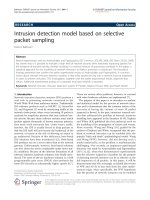
A schematic model of the fabrication process of a CNT
device is shown in Fig. 1. First, the OFPR-800 film was
spin-coated on the glass substrate using a spincoater. Pairs
of areas were fabricated in the PMMA film using photo-
lithography and ordered pairs of electrode patterns were
obtained (Fig. 1a). A 1% APS solution was dropped on the
substrate. It was heated at 45 °C for 15 min until 70% of
the solution had evaporated. After removing the solution by
nitrogen gas blowing, the substrate was heated to 110 °C
for 25 min. The substrate was immersed in pure water for
3–8 min with gentle shaking. Then the substrate was put in
the DMF solution to remove the PMMA layer (Fig. 1b).
Thickness of the sol-gel APS layer was 50–200 nm,
depending on the water immersion time.
CNT immobilization
With a mixture of H
2
SO
4
and HNO
3
, 0.5 mg of SWCNTs
were washed. The solution was centrifuged, and the residue
was suspended in a mixture of H
2
SO
4
, HNO
3
and H
2
O
2
for
208 Nanoscale Res Lett (2007) 2:207–212
123
1 h with ultra-sonication. The obtained black solution was
diluted with water and subjected to dialysis with distilled
water to obtain a neutral pH for the solution. The CNT
solution, which was resonicated immediately before use,
was placed on the patterned substrate at room temperature
for 1 min to adsorb the CNT on the APS layer only
(Fig. 1c). The substrate was washed with water. The
topography of the CNT-immobilized areas was observed
using AC-mode atomic force microscopy (AFM).
Deposition of source and drain metallic electrodes
The patterns used for formation of metallic electrodes were
fabricated on CNT-immobilized areas using a similar
process to that used for formation of areas for immobili-
zation. The electrode was one size larger than the APS
layer to cover the layer (Fig. 1d). As metallic electrodes, a
30-nm-thick Cr film and a 50-nm-thick Au film were
deposited using evaporation deposition (Fig. 1e).
Deposition of gate metallic electrodes
The patterns used for formation of gate metallic electrodes
were fabricated using a similar method of fabricating
source and drain electrodes, except that the APS sol-gel
layer was formed on the CNT and source and drain elec-
trodes (Fig. 1f). After removing the photoresist, the sub-
strate was heated at 185 °C for 1 min to dehydrate and
condense the APS layer.
Topographic images
The topographic images of samples were observed using an
atomic force microscope (MFP-3D; Asylum Research,
USA) and a silicon AFM tip (OCL-400; Olympus Optical
Co. Ltd., Japan). All topographies were observed in air at
room temperature in the AC mode.
I–V measurements and pH measurement
To examine the CNT properties, I
ds
was measured in air by
applying –2 to +4 V to the top gate built on an APS layer
on the CNTs. In addition, I
ds
was plotted as a function of
the potential of the top gate (V
gate
) between the source and
drain (I
ds
–V
gate
curve). The potential between the source
and drain electrode was +0.1 V or –0.1 V. The I
ds
–V
ds
curves were obtained when the gate potential was varied
from –2 V to 4 V.
I
ds
–V
liquid gate
curves were measured in 10 mM phos-
phate buffer with 100 mM KCl at pH 7. An Ag/AgCl
electrode was used as a gate. The potential between the
source and drain electrode was +0.1 V or –0.1 V. The I
ds
–
V
liquid gate
curves were obtained when the gate potential
was varied from –0.55 V to –0.15 V.
Effects of the pH on I
ds
were measured dropping various
pH of 10 mM phosphate buffer on the CNT device:
20 micro L of the buffer was dropped on the CNT and the
Ag/AgCl electrode was used as a reference electrode. The
distance between the CNT device surface and the electrode
was less than 1 mm. As for controlling the solution pH,
10 micro L of the solution was suctioned using a pipette;
then 10 micro L of the other pH solution was added. The
pH of the suctioned solution was measured using a com-
mercial MOS-FET-based pH meter. During measurements,
10 mL of water in dishes was set near the apparatus to
prevent evaporation of the buffer. The potential between
the source and drain electrode was 0.1 V. A semiconductor
characterization system (4155C; Agilent Technologies,
Inc.) was used to measure the I–V curves at room tem-
perature.
Results and discussion
Fabrication of CNT-FET on the cover glass substrate
In this study, SWCNT were washed and modified using a
mixture of sulfuric acid, nitric acid, and hydrogen peroxide.
The SWCNTs, when washed using a strong acid such as
sulfuric acid, display carboxylic acid at the edge and
SWCNT defects. Amorphous carbons, whose surfaces have
carboxylic acid groups, sometimes coat the surface of
SWCNTs. These SWCNTs can be immobilized specifically
on the APS layer in water because of electrostatic inter-
actions between negatively charged SWCNTs caused by
Fig. 1 Schematic model of the
fabrication process of CNT-FET
on a cover-glass substrate
Nanoscale Res Lett (2007) 2:207–212 209
123
carboxylic acid groups and the positively charged APS
layer. Recently, we found that the sol-gel layer of APS was
able to bind bundles of SWCNTs specifically in an aqueous
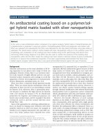
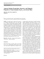
condition. The surface topography of the cover glass was
measured using AFM after immobilization of the bundles
on the APS sol-gel layer; it is shown in Fig. 2. As shown in
Fig. 2, bundles of the SWCNT bound specifically to the
sol-gel layer. Some were located between the planned area
of the source and drain electrodes. The APS layer thickness
was controlled by controlling the immersion time in pure
water before the lift off process using DMF (data not
shown). For a thick layer of greater than 100-nm thickness,
the number of SWCNT bundles on the layer increased and
some nanotubes ran off the edge. For a thin layer, e.g., a
less than 10-nm-thick layer, their number decreased and
almost all nanotubes were immobilized on the layer. We
applied the phenomena of running off the bundles from the
edge of the APS layer for immobilizing SWCNTs between
the planned electrodes areas. In this study, we controlled
the layer thickness as 50–400 nm so that the SWCNT was
able to connect to the source and drain area after electrode
deposition. When washing the substrate using pure water
after immobilization of SWCNT on it, the direction of the
nitrogen gas flow for drying the surface was controlled
from the source to the drain or the drain to source
electrode. Using successive processing, efficiency for
localizing the bundles between the electrodes was
improved over that of using a single layer of APS.
After deposition of the source and drain electrodes, the
top gate was fabricated on a 500-nm-thick APS layer on
nanotubes and source and drain electrodes (Fig. 1f). We
used APS as an insulator. We used only SWCNT devices
for which the current from the top gate to source or drain
electrodes was negligible: less than 10 nA, for I
ds
. The I
ds
was measured in air when V
gate
was applied as –2–+4 V.
The I
ds
–V
gate
curves of the SWCNT device on the cover
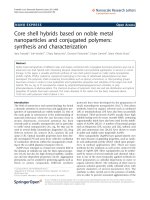
glass are shown in Fig. 3, which showed n-type FET
properties. When the potential was applied from the back
of the device, I
ds
–V
gate
curves of the device showed no FET
properties because 0.12–0.15-mm-thick glass was a suffi-
ciently high-dielectric material that it intercepted the
electrical flux line from the back gate. The I
ds
increased
with increasing the gate potential, which suggests that the
SWCNT device in Fig. 1f shows n-type FET. In Fig. 3, I
ds
at –2 V of the gate potential did not reduce to zero. That
phenomenon might occur because of existence of con-
ductive SWCNTs between the source and drain electrodes.
Controlling the number of SWCNTs and selective immo-
bilization of semi-conductive SWCNTs are left as objec-
tives of future studies.
A CNT device on the silicon oxide layer is known to
show p-type FET as a result of the electron withdrawal of
the CNT by adsorption of oxygen gas [14]. Effects of
molecule binding to the CNT surface have been investi-
gated by many research groups. Reportedly, the APS
molecule changes the electric properties of the CNT-FET
device from p-type to n-type [15]. In this study, a lone pair
of amino group of APS molecules can become an electron
donor and the CNTs will be doped negatively to overcome
the effect of the oxygen molecules. These results suggest
that a p-type CNT-FET device was fabricated on the glass
substrate before fabrication of the insulator by APS on the
CNT device (Fig. 1e).
Fig. 2 Surface topography of the electrode planned site on the cover
glass after immobilization of CNT on it. The inset shows a
comprehensive image of the surface
Fig. 3 A typical I
ds
–V
gate
curve of the rope CNT elements built on a
cover glass substrate. The potential of 0.1 V (solid line) and -0.1 V
(dotted line) was applied to the source electrode; 0 V was applied to
the drain electrode.
210 Nanoscale Res Lett (2007) 2:207–212
123
pH detection using the CNT-FET device on the glass
substrate
We also investigated the effect of pH on the SWCNT-FET
device because aggregation of the aqueous SWCNT dis-
persion is controllable by changing the pH. For this
experiment, we used a SWCNT-FET device without the
insulator layer, as shown in Fig. 1e.
We investigated the properties of the CNT-FET device
shown in Fig. 1e in buffer using the Ag/AgCl electrode
as the gate so that the buffer on CNT acts as a liquid
gate. The I-V
liquid gate
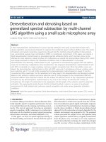
curves are shown in the inset of
Fig. 4. The I
ds
increased with decreasing the gate po-
tential, which suggests that the SWCNT device in Fig. 1e
shows p-type FET and that positive hole in SWCNT is
major carrier. This result is compatible with those de-
scribed in section ‘‘Fabrication of CNT-FET on the cover
glass substrate’’. The droplets of various pH buffers were
dropped on the SWCNT-FET on a glass substrate. The
current increased or decreased after dropping various pH
solutions with high reproducibility (Fig. 4). Because a
proton is an electron acceptor, the proton was able to
bind to the SWCNT surface. It accepted an electron from
the p-orbital of the SWCNT. Acceptance of the electron
from the SWCNT induces generation of a positive hole
in the SWCNT; decreasing the pH would increase gen-
eration of electron hole in p-type SWCNT and contribute
to increasing the I
ds
. The response of the current was
higher in an acidic condition, pH 3–5, than in almost
neutral pH of pH 6–8. These phenomena seem to be
attributable to the carboxylic acid groups that were
introduced on the surface of the SWCNT by a CNT
washing processes. At neutral pH, the carboxylic acid is
dissociated and positively polarized carbon atom of the
carbonyl group is neutralized by resonance effects from
oxygen anion. However, the carboxylic group is proton-
ated at pH 3 and the positively polarized carbon atom is
not stabilized by the resonance. The positively polarized
carbon atom might withdraw an electron from SWCNT,
which might subsequently induce generation of positive
hole in SWCNT. However, detailed elucidation of the
principle of pH sensing using the device remains as a
subject for future study.
Measurement of pH change on a local area on a sub-
cellular compartment, a cell, or a cell tissue is crucial to
clarify the mechanism of the reaction or signal transfer
from a biological point of view. By cultivating the cell or
immobilizing a liposome with a membrane protein on the
CNT device, we could investigate the local pH change on
the cell tissue using the CNT-FET and an optical micro-
scope simultaneously because the size of the cell is greater
than micrometer scale, whereas the CNT device size is sub-
micrometer scale. Because glass substrates are commonly
used for cultivating cells, CNT-FET on a glass substrate
might provide advantages over the use of MOS-FET or
commercial pH meters for detection of pH change.
These results suggest that the changing environments
around the SWCNT were detected using the SWCNT-FET
on cover glass; it might detect various kinds of biomole-
cules by modification of carboxylic acid of SWCNT or
adsorption of biomolecules such as CNT-FET on a silicon
oxide substrate. Because the SWCNT on the device has
many carboxylic acid groups, efficiency of the immobili-
zation of a biomolecule might be higher than other fabri-
cation methods that contribute to the sensitivity of the
sensor.
These results also indicated that, because the sol-gel
layer of APS was formed easily on various substrates,
SWCNT-FET can be built not only on a cover glass but
also on plastic, ceramics, silicon oxide, and so on. The
SWCNT-FET device presents the opportunity for com-
bined construction of other apparatus such as optical
microscopes, which are sometimes used as a TIRF system
for observing a single-molecule level interaction by this
device.
Conclusion
Using the sol-gel layer of APS for immobilization of
SWCNT between the source and drain electrode, a
SWCNT-FET device can be fabricated on a commercial
Fig. 4 Effect of pH on current through the source and drain
electrode. The CNT-FET was immobilized on a glass substrate. The
potential between the source and drain electrodes is 0.1 V. The inset
shows I–V
liquid gate
curves of the device
Nanoscale Res Lett (2007) 2:207–212 211
123
cover glass. The CNT-FET device shows p-type FET
properties. This device, which can detect pH around the
CNT, might be applicable for biosensors through modifi-
cation of the CNT surface.
Acknowledgements This work was supported by the Japan Secu-
rities Scholarship Foundation, the Technology and New Energy and
Industrial Technology Development Organization (NEDO), and
Special Coordination Funds for Promoting Science.
References
1. Y. Cui, Q. Wei, H. Park, C.M. Lieber, Science 293, 1289 (2001)
2. F. Patolsky, G. Zheng, O. Hayden, M. Lakadamyali, X. Zhuang,
C.M. Lieber, Proc. Natl. Acad. Sci. USA. 101, 14017 (2004)
3. C. Staii, J. Johnson, T. Alan, Nano Lett. 5, 1774 (2005)
4. R.J. Chen, H.C. Choi, S. Bangsaruntip, E. Yenilmez, X. Tang, Q.
Wang, Y L. Chang, H. Dai, J. Am. Chem. Soc. 126, 1563 (2004)
5. S. Takeda, A. Sbagyo, Y. Sakoda, A. Ishii, M. Sawamura, K.
Sueoka, H. Kida, K. Mukasa, K. Matsumoto, Biosens. Bioelec-
tron. 21, 201 (2005)
6. J. Kong, N.R. Franklin, C. Zhou, M.G. Chapline, S. Peng, K.
Cho, H. Dai, Science 287, 622 (2000)
7. J. Wang, Analyst 130, 421 (2005)
8. A. Modi, N. Koratkar, E. Lass, B. Wei, P.M. Ajayan, Nature 424,
171 (2003)
9. Q. Yu, G. Qin, H. Li, Z. Xia, Y. Nian, S S. Pei, J. Phys. Chem. B
110, 22676 (2006)
10. J. Zhu, M. Yudasaka, M. Zhang, D. Kasuya, S. Iijima, Nano Lett
3, 1239 (2003)
11. K.H. Choi, J.P. Bourgoin, S. Auvray, D. Esteve, G.S. Duesberg,
S. Roth, M. Burgharm, Surf. Sci. 462, 195 (2000)
12. S.P. Auvray, V. Derycke, M. Goffman, A. Filoramo, O. Jost, J P.
Bourgoin, Nano Lett 5, 451 (2005)
13. M. Lee, J. Im, S. Myung, J. Kang, L. Huang, Y K. Kwon, S.
Hong, Nature Nanotechnology 1, 67 (2006)
14. S H. Jhi, S.G. Louie, M.L. Cohen, Phys. Rev. Lett 85, 1710
(2000)
15. M. Shim, A. Javey, N.W.S. Kam, H. Dai, J. Am. Chem. Soc 123,
11512 (2001)
212 Nanoscale Res Lett (2007) 2:207–212
123